1
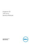
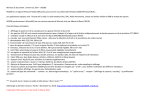
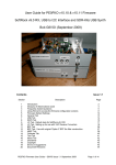
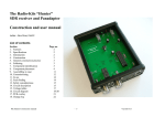
SoftRock RXTX Ensemble USB Interface DD+ Reference 1 Purpose and Function The USB interface provides a way for the PC, running SDR (Software Defined Radio) software to control the local oscillator and PTT functions. The transceiver is controlled by an Attiny85 microcontroller, programmed as a USB device to provide PTT control, paddles input, and local oscillator frequency control, in a galvanically isolated area of the PCB. 1 Theory and Design This is a really neat design for USB using only a small microprocessor and a handful of parts Speed is USB 1.0 at 1.5 Mbits/sec which would seem to slow but it is only used for control, the Rx and Tx data is not passed through the USB bus but instead is passed as analog stereo to and from the PC sound card. Only Local Oscillator frequency selection, CW1, CW2 and PTT control signals, are passed across the USB interface. The assembly manual provides credit and a link to PE0FKO for the firmware and links to his website at http://home.ict.nl/~fredkrom/pe0fko/SR-V9Si570/index.shtml#install That web page states the firmware is based on the free USB AVR CODE by DG8SAQand links to http://www.obdev.at/products/vusb/index.html. Under Links this web page refers to http://www.xs4all.nl/~dicks/avr/usbtiny/ where the following description of this circuitry is found. USBtiny is a software implementation of the USB low-speed protocol for the Atmel ATtiny microcontrollers. Of course, it will also work on the ATmega series. The software is written for an William R. Robinson Jr. AJ4MC 2011 All rights Reserved p1of 12 SoftRock RXTX Ensemble USB Interface AVR clocked at 12 MHz. At this frequency, each bit on the USB bus takes 8 clock cycles, and with a lot of trickery, it is possible to decode and encode the USB waveforms by software. The USB driver needs approximately 1250 to 1350 bytes of flash space (excluding the optional identification strings), depending on the configuration and compiler version, and 46 bytes RAM (excluding stack space). The C interface consists of 3 to 5 functions, depending on the configuration. USB uses two differential data signals, D+ and D-, which are normally complementary. However, the end of a packet is signalled by pulling both signals low. Data is not transmitted directly on the USB bus, it is NRZI encoded first. This means that a "0" bit is encoded as a bit change, and a "1" bit is encoded as no bit change. After 6 "1" bits, "bit stuffing" takes place to force a change on the USB signal lines. The software is interrupt driven: the start of a USB packet triggers an interrupt. The interrupt handler synchronizes with the sync byte, removes the NRZI encoding and bit stuffing, and stores the packed in one of the two RAM buffers. Two buffers are used so that the next packet can be received while the current one is being processed. Depending on the packet type, a reply packed may be sent back immediately in the interrupt handler. 2 USB CONTROL The 3.3V zener diodes D1 and D2 are used to reduce the 5 volt outputs from the ATTiny85 to 3.3 volts. (This complies with the USB requirement of a high being between 2.8 and 3.6 Volts. 3 The 68 ohm resistors, R1 and R2 limit the current into the ATTiny85 o (5-3.3V)/68 ohms = 25 mA. o The ATTiny85 has a maximum of 40 mA for each I/O with a 60 mA total. 4(p166-7) R5 is used to pull up D- to signal to the host PC that the device that this is a low speed device. Normally this is done with a 1.5K resistor to 3.3V. 3 However in this case it is pulled up to 5V o Current with 3.3V across a 1.5Kohm resistor I = 3.3V/1.5K = 2.2 mA o Resistor for same current pulled up to 5V R= 5V/ 2.2mA = 2.27K R5 and R2 both limit the current and add up to 2.268 ohms well within 5% resistor tolerance R6 provides a weak Pullup on D+ , perhaps it for when the USB is not pulled in. I am not sure if this part is really needed o I detected no failures using CFGSR software with R6 removed. C50 is just a bulk capacitor for the USB 5V power supply to the ATTiny85 I2C ATTiny85 PB1 is used as a bidirectional I/O for the I2C SDA line. ATTiny85 PB3 is used as a bidirectional I/O for the I2C SDC line. R10 and R9 provide the required pull up resistors required by the I2C protocol. 5 The ATTiny85 I/O are tri-stateable so can emulate the required Open-drain behavior. 4(p55) William R. Robinson Jr. AJ4MC 2011 All rights Reserved p2of 12 SoftRock RXTX Ensemble USB Interface CW1 INPUT CW1 comes from J2-5 and goes to U1-1 (PB5). The input is active low. R3 provides a pull up resistor so the input does not float when the key/paddles are not connected or open. R8 limits the current into/out of the ATTiny85 below the required o When the J2-5 is floating the current from the 5V supply and into the ATTiny85 is o I=5V/(4.7K+4.7K) or ~ 0.5 mA. o When the J2-5 is closed to ground the current from the 5V supply is o I=5V/(4.7K) or ~ 1.0 mA. CW2 INPUT/SDA out THE ATTiny85 PB1 Is used for two purposes, It is used as an output (along with PB3) to control the Local Oscillator Frequency, and it is use as an input for CW2 from J2-2 This is compatible because conceptually the user would not want to be transmitting while adjusting the output frequency. Both I2C and the paddles use a pull up resistor for High values so it is not obvious to me why R4, R7 and Q1 are required. PTT ISOLATION U4 provides opto-isolation from the USB power and the rest of the card R11 limits the current to the LED in U4. Th opto-isolator has a Forward voltage of 1.2V minimum and a max forward current of 20mA. 6 o R11min = (5-1.2)V/20mA = 190 ohms o So 470 ohms is well within the requirements William R. Robinson Jr. AJ4MC 2011 All rights Reserved p3of 12 SoftRock RXTX Ensemble USB Interface Calculated NONE Simulation NONE William R. Robinson Jr. AJ4MC 2011 All rights Reserved p4of 12 SoftRock RXTX Ensemble USB Interface Real Circuit USB CONTROL The Trace below shows the zener diodes keeping the D- output back to the PC at 3.3 Volts. The pulses on the left side are from the ATTiny to the PC. o D- is at the zenor voltage of 3.3Volts o PB2 is about 180 mV higher than D- due to the voltage drop across the 68 ohm R2 The pulses on the right are from the PC to the ATTiny85 o D- is higher than the zenor voltage of 3.3Volts suggesting that the PC has significant drive power o PB2 is about 110 mV higher than D- due to the voltage drop across the 68 ohm R2 o The voltage drop across the 68 ohm resistor is less as little current goes into PB2 when it is an input then comes out when it is an output what little current that does flow is more likely through the 2.2K R5 How zenors and 68 ohm resistors do voltage conversion o Magenta = Do Green = PB2 The two traces below show the changes when connected to the PC directly verses using a USB hub. Changing from PC USB port to USB HUB changes voltages on the right side only suggesting the right side is from the PC to the ATTiny William R. Robinson Jr. AJ4MC 2011 All rights Reserved p5of 12 SoftRock RXTX Ensemble USB Interface With HUB o Top D+ o BOT D- With PC o Top D+ o BOT D- William R. Robinson Jr. AJ4MC 2011 All rights Reserved p6of 12 SoftRock RXTX Ensemble USB Interface USB PAYLOADS A USB traffic analyzer was used to study the traffic across the USB interface between the PC and the ATTiny85. o A screen shoot from the tool is shown below o The table below shows some of the frequency vales that were requested using CFGSR software and the values sent across the interface Requested Frequency Packet Payload 2,000,000 1000000 16777216 8.388608000000 2,000,001 1000008 16777224 8.388607805696 2,000,002 1000011 16777233 8.388608111392 2,000,003 1000019 16777241 8.388607917088 2,000,004 1000022 16777250 8.388608222784 2,000,005 100002A 16777258 8.388608028480 2,000,006 1000032 16777266 8.388607834177 2,000,007 100003b 16777275 8.388608139872 2,000,008 1000043 16777283 8.388607945568 2,000,009 100004b 16777291 8.388607751265 2,000,010 1000054 16777300 8.388608056960 2,000,020 10000A8 16777384 8.388608113919 2,000,030 10000FC 16777468 8.388608170877 2,000,040 1000150 16777552 8.388608227835 William R. Robinson Jr. Dec(packet) AJ4MC 2011 All rights Reserved Packet value/ Requesed Frequency p7of 12 SoftRock RXTX Ensemble USB Interface 2,000,050 10001a3 16777635 8.388607784805 2,000,060 10001F7 16777719 8.388607841765 2,000,070 100024B 16777803 8.388607898724 2,000,080 100029F 16777887 8.388607955682 2,000,090 10002F3 16777971 8.388608012639 2,000,100 1000347 16778055 8.388608069597 2,000,110 100039B 16778139 8.388608126553 30,000,000 0F000000 251658240 31,000,000 0F800000 260046848 8.388608000000 32,000,000 10000000 268435456 8.388608000000 33,000,000 10800000 276824064 8.388608000000 34,000,000 11000000 285212672 8.388608000000 35,000,000 11800000 293601280 8.388608000000 36,000,000 12000000 301989888 8.388608000000 37,000,000 12800000 310378496 8.388608000000 38,000,000 13000000 318767104 8.388608000000 39,000,000 13800000 327155712 8.388608000000 40,000,000 14000000 335544320 8.388608000000 o It appears that the value sent is the requested frequency * 8.3886080 o I also noted that 2 raised to the 23 (0x800000) is equal to 8388608 decimal. o I do not know of any reason for this ratio other than to speculate it is useful for the firmware inside the ATTiny85 o I posted this question to the softrock40 Interest group have not received any replies. http://groups.yahoo.com/group/softrock40/ # 52262 USB Data Packets Format Jan 28, 2011 6:36 pm I2C Below is a logic trace of the ATTiny85 accessing the Si570 (Write to address 55) Note that clock stretching is very evident. The byte takes about 145 usec for a rate of about 55 Kbits/sec. CW1 INPUT William R. Robinson Jr. AJ4MC 2011 All rights Reserved p8of 12 SoftRock RXTX Ensemble USB Interface The trace below shows the keyin on J2-5 and input to the ATTiny85 on PB5. o Magenta = J2-5 o Green = PB5 o Note R8 adds little or no delay CW2 INPUT/SDA out CFGSR software does not prevent the simultaneous use of PB1 for I2C and CW2 o In fact this often lead to the USB being “Disconnected” by the PC. The trace below shows the key being closed during an I2C communications. o It appears that the I2C may be attempting to drive high the SDA line instead of letting the pull up resistor bring the line high. Keying on CW2 interrupting I2C o Magenta = J2-2 o Green = PB1 William R. Robinson Jr. AJ4MC 2011 All rights Reserved p9of 12 SoftRock RXTX Ensemble USB Interface The screen shots below show that the Si570 registers are not readable during when CW2 is low o CW2 high o CW2 low William R. Robinson Jr. AJ4MC 2011 All rights Reserved p10of 12 SoftRock RXTX Ensemble USB Interface PTT ISOLATION PTT using PowerSDR-IQ v.1.12.20 Tune button o Magenta = PB4 after R11 on U4-1 o Green = /PTT on U4-4 o Note time to turn on /PTT is about 6 uSec William R. Robinson Jr. AJ4MC 2011 All rights Reserved p11of 12 SoftRock RXTX Ensemble USB Interface References 1. Robson, Richard R. Sr., WB5RVZ, Ensemble RXTX Project, http://www.wb5rvz.com/sdr/ensemble/index.htm, online, accessed 2011. 2. Dick Streeland, USBtiny, http://www.xs4all.nl/~dicks/avr/usbtiny/, online, accessed 2011. 3. UNKNOWN, USB Overview, http://en.wikipedia.org/wiki/USB#USB_1.0, online, accessed 2011. 4. ATMEL, 8-bit Microcontroller with 2/4/8K Bytes In-System Programmable Flash,http://www.farnell.com/datasheets/3892.pdf, online, accessed 2011. 5. NXP(Phillips), UM10204 I2C-bus specification and user manual Rev. 03 — 19 June 2007 http://www.nxp.com/documents/user_manual/UM10204.pdf, p8, online, accessed 2011. 6. LITEON, High Density MountingType Photocoupler LTV-817 series, http://www.us.liteon.com/downloads/LTV-817-827-847.PDF, p12 -112, online, accessed 2011. William R. Robinson Jr. AJ4MC 2011 All rights Reserved p12of 12