1
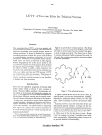
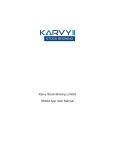
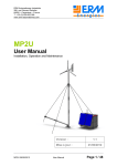
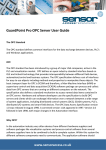
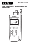
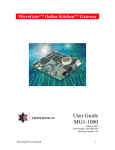
X‐PIN & X‐PROX User Manual The X‐PIN is a single door controller which uses PIN only. The X‐PROX is a single door controller that uses PIN and proximity technology. All electronics are within the housing of the reader. The X‐PIN and X‐PROX can be connected to a door con‐
tact and request to exit button to allow the system to send a signal to a sounder in case the door has been forced or left open. X‐PIN X‐PROX VDC 12vDC‐24vDC 12vDC‐24vDC VAC 12vDC‐24vAC 16vDC‐24vAC Maximum Heater On Input Current Heater Off (12vDC) 130mA 145mA 610mA 625mA Standby In‐
put Current (12vDC) Heater On 70mA 85mA Heater Off 550mA 365mA 2A 2A REX Input Normally Open Normally Open Aux Input Normally Open Normally Open Max Proximity Read Range N/A 65mm Proximity Card Compati‐
bility N/A SP‐SHL, SP‐ISO, SP‐KEY, SP‐DISC Two 3 Coloured LED Two 3 Coloured LED ‐20°C to 60°C ‐20°C to 60°C Meets IP64 Meets IP64 Input Voltage Maximum Relay Current LED Indicators Operating Temperatures Outdoor Usage Dimensions Weight 120mm (H) x 76mm (W) x 22mm (D) 521g www.sensoraccess.co.uk 01
X‐PIN & X‐PROX User Manual Key Features •
•
•
•
•
•
•
•
•
•
•
•
•
Wiring The Controller The Controllers are provided with a sixty cen‐
timeter, pre‐wired, 10 conductor cables. 500 Users Water and vandal resistant Programmable Backlight and active LED control Three user levels: normal; secure; master Three modes of operation: normal; bypass; secure Integrated proximity card reader (X‐PROX only) Selectable PIN code length up to 8 digits Auxiliary input and auxiliary output Input for Request to Exit (REX) button Search feature for easy maintenance of user codes Two tri‐colored status/programming LED indicators Lockout feature on wrong entries Programmable lock strike release time. Colour Description Red V Input Black Ground Green REX/BL White In/Monitor Purple Lock : Com Grey Lock : N.O. Brown Lock : N.C. Blue Aux : Com Yellow Aux : N.O. Orange Aux : N.C. www.sensoraccess.co.uk 02 X‐PIN & X‐PROX User Manual Pre‐Wired Connection for Lock Strike Relay & Rex www.sensoraccess.co.uk 03
X‐PIN & X‐PROX User Manual Note: •
•
In this chapter, ‘Code’ refers to a PIN code or proximity card depending on the unit you have Memory slots can be a proximity card or PIN code depending on the unit you have MODES OF OPERATION Normal Mode (Default) • Mode indicator is green. In normal mode, the door is locked until a valid primary code is presented to the controller. The controller can only be programmed in normal mode. Secure Mode • Mode indicator is red. Only secure and master users can access the premises in secure mode. A secure user must enter a primary and secondary code to gain entry. Once the primary code has been entered, the Door indicator will flash green for 10 seconds. During this time, the secondary code must be entered. A master user only needs to enter his code to gain entry. Bypass Mode • Mode indicator is orange. In bypass mode, access to the premises is dependent on the Lock Strike relays; that is, if the relay is pro‐
grammed for failsafe operation or fail‐secure operation. When the Lock Strike relay is programmed for fail secure operation, the door is locked until the star button is depressed. When the Lock Strike relay is programmed for failsafe operation, the door is constantly unlocked. In case of power failure, once the power is restored, the controller will return to normal mode, for security rea‐
sons. USER LEVELS The X‐PIN & X‐PROX Access Control units accept up to 500 users and provide entry via the use of codes. Each user is allocated two memory slots: Memory Slot 1 (primary code) and Memory Slot 2 (secondary code). The way in which the two memory slots are programmed, determines a user’s access level and also establishes ac‐
cess is granted for each of the three modes of operation. Normal User A normal user only has a primary code and is granted access only when the controller is in its normal or bypass mode www.sensoraccess.co.uk 04 X‐PIN & X‐PROX User Manual Secure User A secure user must have a primary and secondary code assigned, and the two codes must not be the same. The secure user can gain access in any mode of operation. In normal mode the secure user must use the primary code to gain entry. In secure mode, the secure user must first enter the primary and then the secondary code, in order to gain entry. Master User A master user must have identical primary and secondary codes assigned. The codes are entered with the same proximity card or the same PIN. The master user can gain access during any mode of operation by entering their code only once
SWITCHING OPERATIONAL MODES From Normal to Secure Mode The default factory setting for the normal / secure code is 3838 1) Enter the normal / secure code • Mode indicator will flash red. 2) Depress the # key to confirm the Mode change • Mode indicator is red. The auxiliary input of the controller can also be used to switch the mode of operation from secure to normal and vice versa, if the auxiliary input is selected it de‐activates the Normal/Secure mode code. Refer to Setting the Auxiliary Mode From Secure to Normal Mode The default factory setting for the normal / secure code is 3838. 1) Enter the normal / secure code. • Mode indicator will flash green. 2) Depress the # key to confirm the Mode change. • Mode indicator will turn green. The auxiliary input of the controller can also be used to switch the mode of operation from secure to normal and vice versa, if the auxiliary input is selected it de‐activates the Norma/Secure mode code. Refer to Setting the Auxiliary Mode www.sensoraccess.co.uk 05
X‐PIN & X‐PROX User Manual From Normal to Bypass Mode By default, there is no normal / bypass code. The normal / bypass code must first be programmed to use this function. Refer to paragraph “to create / modify the normal / bypass code” 1) Enter the normal / bypass code • Mode indicator will flash orange. 2) Depress the # key to confirm the mode change • Mode indicator will turn orange From Bypass to Normal Mode 1) Enter the normal / bypass code. • Mode indicator will flash green 2) Depress the # key to confirm the mode change • Mode indicator will turn green Request to Exit Button (REX) The REX pushbutton is located within the premises and is used to open the door from the inside. It is usually lo‐
cated in a convenient location (e.g.: next to the door or at a receptionist’s desk). The function of the REX pushbutton depends on the Lock Strike relay, whether it is programmed for failsafe or for fail secure operation. Failsafe Operation: From the moment the REX pushbutton is depressed, the door will be unlocked until the REX pushbutton is re‐
leased. In this case the Lock Strike relay only begins its countdown once the REX pushbutton has been released. This feature is designed to keep the door open, when used in conjunction with fire systems. Fail Secure Operation: From the moment the REX pushbutton is depressed, the door will be unlocked until the Lock Strike release time has elapsed. After this time, the door will be locked, even if the REX pushbutton has not been released. Lockout Feature (Keypad / Card Tamper) In case the controller is presented with wrong codes, (PIN or Card) consecutively several times the unit goes into lockout mode. When a lockout occurs, the controller keypad and reader are de‐activated so no codes can be en‐
tered until the set lockout period expires. During Lockout, Mode LED is Off, Door LED flashes Red, and the controller beeps every two seconds. Refer to programming for detailed programming of this feature. www.sensoraccess.co.uk 06 X‐PIN & X‐PROX User Manual PROGRAMMING Programming the X‐PIN & X‐PROX Access Control unit is done solely via the unit’s keypad‐driven Programming Menu System. To reach the Programming Menu System, the controller must first be placed into Programming Mode. Refer to Entering Programming Mode. During the manufacturing process, certain codes and settings are pre‐programmed. These settings are the called default factory settings. The table below shows all the programming menus with default factory codes and settings Default Menu No Description 4 Digit 5 Digit 6 Digit 8 Digit 1 Change open code 2580 25802 258025 25802580 2 Change auxiliary code 0852 08520 085208 08520852 3 Change program code 1234 12341 123412 12341234 4 Change normal / secure code 3838 38383 383838 38383838 5 Change normal / bypass code ‐ 6 Change door release time 0004 6 Define auxiliary inputs / outputs 2004 6 Enable or disable keypad heater 3000 6 Set lockout feature 4000 6 Backlight & LED behavior 5100 7 Enroll proximity cards, PIN or both ‐ 8 Delete proximity cards or PIN ‐ 9 Code assignment with strike/auxiliary ‐ 0 Return to factory defaults/Change PIN code length ‐ www.sensoraccess.co.uk 07
X‐PIN & X‐PROX User Manual ENTERING THE PROGRAMMING MODE Note: •
•
•
The controller must be in normal mode to enter the programming mode. The factory default 4 digit programming code is 1234 If a programming code is not entered within 5 seconds the controller will return to its normal mode. 1) Depress the # key twice, within 0.5 seconds. • Mode indicator will turn off. • Door indicator will turn red. 2) Enter your programming code. If the programming code is valid, the door Indicator will turn green and the controller will enter the programming mode EXITING THE PROGRAMMING MODE Note: •
•
Wrong enteries may reset the controller back to its normal mode If no key is pressed for 1 minute, while in programming mode, the controller will exit programming mode and return to its normal mode To exit the programming mode, depress the # key twice, within 0.5 seconds • You will hear three beeps. • The door indicator will be off. • The mode indicator will turn green. The above indicates that the controller has returned to its normal mode. www.sensoraccess.co.uk 08 X‐PIN & X‐PROX User Manual CHANGING THE OPEN CODE The open code is mainly used as a method to quickly test the Lock Strike relay during installation. The factory 4‐digit default setting for the open code is 2580. Note: •
•
•
Open code does not function in secure mode Wrong entries: you will hear a long beep and the controller will return to its normal mode Code 0000 will erase and deactivate the open code 1) Enter the programming mode. 2) Depress 1 to enter Menu 1 •The Mode indicator will turn red. 3) Enter the new code you wish to set as open code. 4) System returns to its normal mode. • You will hear three beeps The Door indicator will turn off. • The Mode indicator will turn green CHANGING THE AUXILIARY CODE The auxiliary code is mainly used as a method to quickly test the Auxiliary relay during installation. The default 4‐
Digit factory setting for the auxiliary code is 0852. For security reasons when the first user is added to the controller or the open code is changed, the default auxil‐
iary code will automatically be deleted, non‐default codes will not be erased automatically 1) Enter the programming mode 2) Depress 2 to enter Menu 2. • The Mode indicator will turn orange. 3) Enter a new auxiliary code. 4) System returns to its normal mode. • You will hear three beeps. • The Door indicator will turn off. • The Mode indicator will turn green. www.sensoraccess.co.uk 09
X‐PIN & X‐PROX User Manual CHANGING THE PROGRAMMING CODE 1) Enter the programming mode 2) Depress 3 to enter Menu 3 • The Mode indicator will turn green. 3) Enter the new programming code. 4) System returns to its normal mode • You will hear three beeps. • The Door indicator will turn off. • The Mode indicator will turn green CHANGING THE NORMAL/SECURE CODE 1) Enter the programming mode. 2) Depress 4 to enter Menu 4. • The Mode indicator will flash red. 3) Enter the new Normal/Secure code. 4) System returns to its normal mode. • You will hear three beeps • The Door indicator will turn off • The Mode indicator will turn green SETTING AUXILIARY MODES The default auxiliary setting is 2004. 1) Enter the Programming Mode. 2) Depress 6 to enter Menu 6. • The Mode indicator will flash green 3) Construct a code using the instructions hereafter. The Quick Reference Guide for Auxiliary Mode Setting Table provides a quick reference listing for the auxiliary modes www.sensoraccess.co.uk 10 X‐PIN & X‐PROX User Manual Auxiliary Mode In addition to the Lock Strike relay and the Lock Strike REX, the controller features an auxiliary output relay and an auxiliary input whose function is established by the auxiliary mode selection (0 thru 9) The auxiliary mode also determines if the auxiliary output relay is set for failsafe or for fail secure operation. For a more detailed explanation on each auxiliary mode, refer to the Auxiliary Mode Reference table below. Auxiliary Settings Each of the auxiliary modes has a two‐digit setting which affects the operation of the related relay(s). 4) System returns to its normal mode. • You will hear three beeps. • The Door indicator will turn off. • The Mode indicator will turn green. Quick Reference Guide for Auxiliary Setting Auxiliary Mode Auxiliary Input Function Auxiliary Output Activated by Auxiliary Relay Auxiliary Settings (In Seconds) 0 AUX REX Valid code or AUX REX N.O. 01 to 99 Aux. relay release time 00 Aux relay toggle 1 Normal/Secure switch Valid code N.O. 01 to 99 Aux. relay release time 00 Aux relay toggle 2 Normal/Secure switch Star Button (*) N.O. 01 to 99 Aux. relay release time 00 Aux relay toggle 3 Normal/Secure switch Tamper event N.C. 01 to 99 Aux. relay release time 00 Aux relay toggle 4 Normal/Secure switch Direct shunt N.O. 01 to 99 Shunt time 5 Door Monitor Shunt N.C. 01 to 99 Maximum shunt time 6 Door Monitor Forced door N.C. 01 to 99 Forced delay 7 Door Monitor Door ajar N.C. 01 to 99 Ajar delay 8 LED control – Green Valid code N.O. 01 to 99 Aux. relay release time 00 Aux relay toggle 9 LED control – Red Valid code N.O. 01 to 99 Aux. relay release time 00 Aux relay toggle www.sensoraccess.co.uk 11
X‐PIN & X‐PROX User Manual AUXILIARY MODE 0 Auxiliary input function: Activates the auxiliary output Auxiliary output activated by: Valid user code, Auxiliary code, Auxiliary input E.g. In auxiliary mode 0, the controller can function as a two‐door controller. The auxiliary relay is to be attached to the lock on the second door. The auxiliary setting defines the door open time for the second door. The auxil‐
iary input is to be attached to the REX pushbutton for the second door. Door Monitor input feature for the sec‐
ond door is not enabled when using this mode. AUXILIARY MODE 1 Auxiliary input function: Toggles normal/secure modes Auxiliary output activated by: Valid user code, Auxiliary code E.g. In auxiliary mode 1, the controller can function as a two‐door controller. The auxiliary relay is to be attached to the lock on the second door. REX feature for the second door is not enabled when using this mode. The auxil‐
iary setting defines the door open time for the second door. The auxiliary input can switch the mode of opera‐
tion of the controller between normal and secure mode. By connecting a switch timer or alarm system output to the auxiliary input, the controller can be automatically switched from normal mode (during office hours) to se‐
cure mode (after office hours). AUXILIARY MODE 2 Auxiliary input function: Toggles normal/secure modes Auxiliary output activated by: Star Button (*) E.g. In auxiliary mode 2, the auxiliary relay can function as a general purpose time switch that can be activated when the star button is depressed. The auxiliary setting establishes for how long the auxiliary relay is to be acti‐
vated. The auxiliary input can switch the mode of operation of the controller between normal and secure mode. By connecting a switch timer or alarm system output to the auxiliary input, the controller can be automatically switched from normal mode (during office hours) to secure mode (after office hours). AUXILIARY MODE 3 Auxiliary input function: Toggles normal/secure modes Auxiliary output activated by: Alarms E.g. In auxiliary mode 3, the auxiliary output is activated if the controller is tampered; that is, if the case is forci‐
bly opened or removed from the wall. The auxiliary input can switch the mode of operation of the controller be‐
tween normal and secure mode. By connecting a switch timer or alarm system output to the auxiliary input, the controller can be automatically switched from normal mode (during office hours) to secure mode (after office hours). www.sensoraccess.co.uk 12 X‐PIN & X‐PROX User Manual AUXILIARY MODE 4 Auxiliary input function: Toggles normal/secure modes Auxiliary output activated by: direct shunt (explanation below) E.g. In auxiliary mode 4, the controller is capable of bypassing an alarm zone by shunting an alarm system’s door sensor. The auxiliary output is to be wired in parallel to the door sensor output. When in use, the auxiliary out‐
put is normally open and the door sensor functions normally. When a valid code is entered, the auxiliary relay shunts the door sensor for the duration of the shunt time, as defined by the auxiliary setting. If the door is left open longer than the shunt time, an alarm will be triggered. AUXILIARY MODE 5 Auxiliary input function: Door Monitor Auxiliary output activated by: Shunt (explanation below) E.g. In auxiliary mode 5, the controller is capable of shunting an alarm system. In this mode, the auxiliary input is to be wired to the magnetic contact switch on the door. The auxiliary relay is wired to the alarm system. With‐
out a valid code entered, the auxiliary relay will match the condition of the magnetic contact switch; if the door opens, the auxiliary relay will open; if the door closes, the auxiliary relay will close. When a valid code is entered, a count down for maximum shunt time, as defined by the auxiliary setting, begins; if the door is not closed be‐
fore the maximum shunt time, the alarm will be triggered. AUXILIARY MODE 6 Auxiliary input function: Door Monitor Auxiliary output activated by: Forced entry E.g. In auxiliary mode 6, the controller can trigger the auxiliary relay if the door has been forced. If the Siren Set‐
tings is enabled the siren will be activated. In this mode, the auxiliary input functions as a door monitor switch and is wired to the magnetic contact switch on the door. The auxiliary relay is to be wired to the alarm system. If the door is forced open, the controller will wait for the period of the forced door delay time to elapse and then, it will activate the auxiliary relay. The auxiliary setting sets the forced door delay period AUXILIARY MODE 7 Auxiliary input function: Door Monitor Auxiliary output activated by: Door Ajar (door held open) E.g. In auxiliary mode 7, the controller can trigger the auxiliary relay, if it detects that the door has been held open (ajar) too long. In this mode the auxiliary input functions as a door monitor switch and is wired to the mag‐
netic contact switch on the door. The auxiliary relay is to be wired to the alarm system. If the door is opened, the controller will wait for the door ajar delay time to elapse and if the door does not close prior to the end of this period, the controller will activate the auxiliary relay. The auxiliary setting defines the door‐ajar time. www.sensoraccess.co.uk 13
X‐PIN & X‐PROX User Manual AUXILIARY MODE 8 Auxiliary input function: Green LED control Auxiliary output activated by: Valid user code, Auxiliary code E.g. In auxiliary mode 8, the controller can function as a two‐door controller and also provide indicator function‐
ality control. The auxiliary relay is connected to the lock on the second door. The auxiliary setting defines the door open time for the second door. The auxiliary input is used to control the Door indicator. If the auxiliary in‐
put is open, the indicator will flash green; if the auxiliary input is closed, the Door indicator will flash red Note: This mode takes control of the Door indicator LED, The indicator LED will not be lit when: •
A valid code is entered •
While in secure mode, when waiting for a secondary code AUXILIARY MODE 9 Auxiliary input function: Red LED control Auxiliary output activated by: Valid user code, Auxiliary code E.g. In auxiliary mode 9, the controller can function as a two‐door controller and also provide indicator function‐
ality control. The auxiliary relay is connected to the lock on the second door. The auxiliary setting defines the door open time for the second door. The auxiliary input is used to control the indicator. If the auxiliary input is open the Door indicator will flash red; if the auxiliary input is closed the Door indicator will flash green. KEYPAD HEATER OPERATION The controllers contain a built‐in keypad heater. Once the heater circuitry is activated, the heater will turn on when the ambient temperature drops to 4±1°C and will remain on until the keypad temperature rises to 7 °C. When the heater is on, the controller can operate down to an ambient temperature of ‐20°C. When the heater is disabled, theLowest operating temperature is 0°C. The default setting for the keypad heater is disabled state (3000). 1) Enter the programming mode. 2) Depress 6 to enter Menu 6. •
The Mode indicator will flash green. 3) Construct a code using the following instructions: To disable the heater, the fourth digit is set to 0. To enable the heater, the fourth digit is set to 1. www.sensoraccess.co.uk 14 X‐PIN & X‐PROX User Manual SETTING THE LOCKOUT FEATURE In case the controller is presented with wrong codes, (PIN or Card) consecutively several times the unit goes into lockout mode. When a lockout occurs, the controller keypad and reader are locked so no codes can be entered until the set lockout period expires. During Lockout, Mode LED is Off, Door LED flashes Red, and the controller beeps every two seconds. The default setting for the Lockout Feature is 4000 (Lockout Disabled) The default setting for the keypad heater is disabled state (3000). 1) Enter the programming mode. 2) Depress 6 to enter Menu 6. • The Mode indicator will flash green. 3) Construct a code using the following instructions: : Set the number of wrong code attempts, which will cause Lockout between 0 and 9 at‐
tempts. Sets the Duration of the lockout, between 00 and 99, the value is multiplied by ten, resulting in 0‐990 seconds BACKLIGHT and LED BEHAVIOUR The controller allows you to define the way the units' Backlight as well as the Mode and Door LEDs will work. To define the Backlight and LEDs operation: 1) Enter the programming mode. 2) Depress 6 to enter Menu 6. • The Mode indicator will flash green. 3) Construct a code using the following instructions: The first digit is five indicating the backlight and Led option The second key can be 0‐3 indicating the type of activity • Option 0 ‐ LED Active / Backlight Off • Option 1 ‐ LED Active / Backlight On (default) • Option 2 ‐ LED and Backlight Off, both activated on any key press for ten seconds. • Option 3 ‐ LED Active / Backlight Dimmed, backlight activated on any key press for ten sec‐
onds. www.sensoraccess.co.uk 15
X‐PIN & X‐PROX User Manual ENROLLING CODES Primary Codes Definition • Primary codes can only be enrolled to an empty user slot, a slot with no existing primary code in the control‐
ler’s memory. A primary code must be unique; for instance, one user’s primary code may not be the same as that of another user. • Primary codes cannot be the same as system codes, such as: the normal / secure code or the open code. • Users possessing a primary code can gain entry during normal and bypass modes. Secondary Codes Definition • Secondary codes can only be enrolled to a user slot that already includes a primary code. • A Secondary code need not be unique; for instance, one user’s Secondary code may be the same as that of an‐
other User. • Secondary codes cannot be the same as any system codes, such as: the normal / secure code or the open code. • Users possessing secondary codes can gain entry in any mode of operation. • A Secondary code can be the same as the primary code of any user. Primary and Secondary Codes Enrolling Methods There are two methods used to enroll primary and secondary codes: the standard method and the code search method. 1) The standard method is used when the user slot number, for the user you wish to program, is known. You can program both primary and secondary codes using this method. 2) The code search method is mainly used when enrolling a secondary code and the user’s slot code is unknown. The code search method will function only if a user’s primary code is already enrolled and the secondary code is not. Standard Method for Codes Enrolling 1) Enter the programming mode. 2) Depress 7 to enter Menu 7. •
The Door indicator will turn orange. 3) Enter the 3‐digit user slot number into the memory (from 001 to 500) so as to enroll a primary or secondary code. •
For example, the user slot 003 represents user no. 3. www.sensoraccess.co.uk 16 X‐PIN & X‐PROX User Manual 4) At this time three possibilities exist: a. If the selected slot has no primary code, the Mode indicator will flash green, indi‐
cating that the controller is ready to accept a primary code. b. If the selected slot already has a primary code, but no secondary code, the Mode indicator will flash red, indicating that the controller is ready to accept a second‐
dary code. c. If the selected slot already has a primary and secondary code, a long beep will be heard and the controller will return to its normal mode. 5) Enter the code to be assigned as the primary or secondary code for this slot number. If the code that is en‐
tered is valid, the Mode indicator will cease flashing and the controller is ready for the next 3‐digit slot number (step 3) or depress the # key to move to the next slot number (step 4). If you do not wish to continue enrolling codes, depress the # key twice and the controller will return to its normal mode. Search Method for Codes Enrolling The code search method enables to quickly enroll a secondary code for a user whose primary code is known and whose slot number is unknown. 1) Enter the programming mode. 2) Depress 7 to enter Menu 7. •
The Door indicator will turn orange. 3) Enter the 3‐digit user slot number 000. • The Door indicator will flash orange. The controller is now waiting for the primary code of the user. 4) Enter the primary code belonging to the user who needs a secondary code. • The Mode indicator will flash red. If the primary code entered is not valid, a long beep will sound and the controller will wait for a valid primary code. 5) Enter the code to be used as the secondary code. If the secondary code is valid, the controller will beep three times and return to its normal mode. If the secondary code is invalid, the controller will produce a long beep and will wait for a valid secondary code to be entered. www.sensoraccess.co.uk 17
X‐PIN & X‐PROX User Manual DELETING CODES When deleting a user slot, both the primary code and the secondary code are erased. 1) Enter the programming mode. 2) Depress 8 to enter Menu 8. •
The Mode indicator will turn red. 3) Enter the 3‐digit user slot code to be deleted. • The Mode indicator will flash red, indicating the controller is waiting for a programming code to confirm the deletion. If the user slot is empty, a long beep will be heard and the controller will return to its normal mode. 4) Enter your programming code to confirm the deletion. If the programming code is valid, three beeps will be heard and the controller will return to its normal mode. If the programming code is invalid, a long beep will be heard and the controller will return to its normal mode. RELAY CODES ASSIGNMENT When a primary code is enrolled for any user, the user is authorized to activate the Lock Strike relay. However, different user codes may be set to operate the auxiliary relay instead or operate both the Lock strike and auxil‐
iary relay. Assignment of such codes is achievable for any valid user code entered in the controller. 1) Enter the programming mode. 2) Depress 9 to enter Menu 9. • The Mode indicator will turn green. • The Door indicator will turn orange. 3) Enter the 3‐digit user slot for code assignment. • The Door indicator will flash green. 4) Enter the assignment digit for the current user slot: • 1 will activate the Lock Strike relay only default • 2 will activate the Auxiliary relay only • 3 will activate the Lock Strike and Auxiliary relays. If the assignment code is valid, the Mode indicator will stop flashing. The controller is now waiting for another slot number. Depress the # key to move to the next slot or enter a new slot number. If you do not wish to con‐
tinue, depress the # key twice and the controller will return to its normal mode. www.sensoraccess.co.uk 18 X‐PIN & X‐PROX User Manual PIN CODE LENGTH / FACTORY DEFAULT SETTINGS 1) Enter the programming mode. 2) Select the desired pin code length as follows: a. 00 – Returns to factory defaults and sets a 4 digit code. b. 05 ‐ Returns to factory defaults and sets a 5 digit code. c. 06 ‐ Returns to factory defaults and sets a 6 digit code. d. 08 ‐ Returns to factory defaults and sets a 4‐8 digit code. • Both the Mode and Door indicators Will flash red. 3) Enter your programming code. If the programming code is valid, all memory will be erased, you will hear three beeps and the controller will re‐
turn to normal mode If the programming code is invalid you will hear a long beep and the controller will return to normal mode, without erasing the memory contents. REPLACING A PROGRAMMING CODE www.sensoraccess.co.uk 19
X‐PIN & X‐PROX User Manual 1) Remove power from the controller. 2) Depress and hold the REX pushbutton. 3) Apply power to the unit with the REX pushbutton depressed. 4) Release the REX pushbutton. 5) You now have 15 seconds to program a new programming code into the unit using the initial default code, before the controller reverts to the existing code. the default code depends on the pin length selected, refer to the programming Menu table REPLACING A NORMAL/SECURE CODE 1) Remove power from the controller.
2) Depress and hold the REX pushbutton.
3) Apply power to the unit with the REX pushbutton depressed.
4) Release the REX pushbutton.
5) You now have 15 seconds to use the normal/secure code to return to the normal mode. Once in the normal mode, enter
the programming mode to program a new normal/secure code. the default code depends on the pin length selected, refer to
the programming Menu table
Sensor Access Technology Ltd Sensor House 10‐11 Lewes Road Brighton East Sussex BN2 3HP Tel: 01273 242 355 Fax: 01273 235 030 [email protected] www.sensoraccess.co.uk 20