1
CHAPTER 1
Welcome to the GT4500
1.1 Introduction
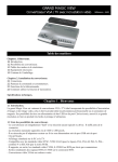
The GT4500 is a state of the art PC to TV converter that incorporates Video Overlay and titling, making it the
ideal solution for in store signs, and training presentations. The OSD Function makes it user friendly. All of this
is made possible at an unprecedented price due to high-resolution integrated chip technology. The portable
design and user-friendly controls make the GT4500 especially easy to use.
1.2 Product Features
•
•
•
•
•
•
•
•
•
•
•
•
•
•
•
•
•
•
•
•
•
•
Pure hardware design, just Plug and Display, no software required.
Supports resolution up to 1600 x l200.
On Screen Display (OSD) operation status.
Power from PS2 or USB port, No need power adaptor.
Simultaneous display on TV and monitor.
Supports NTSC, NTSC-EIAJ (for Japan), PAL, PAL-M, PAL-N,
PAL-combination-N and SECAM (via RGB OUT) video system.
Supports CVBS, S-VIDEO or RGB video outputs by switch change.
Simultaneous RGB and CVBS output signal on RGB out connector.
True 24-bit color digitizer.
Supports Panel and Remote control.
Panel Button supports POWER, GENLOCK, VIDEO SOURCE, FINE TUNE, ZOOM, MENU, and
Position function.
GENLOCK button supports PC mode, OVERLAY mode, MIX mode, MIX/OVERLAY mode.
Video source button supports VIDE01 (CVBS), VIDE02 (S-VIDEO).
MENU button supports Freeze, H-SIZE (Horizontal SIZE), V-SIZE (Vertical SIZE), output
Brightness, output Contrast, output Hue, output Saturation, output Flicker, input Brightness, input
Contrast, input Hue, input Saturation, Color key enable/disable, Luminance key, Red Color key,
Green Color Key, Blue color key, MIX ratio, OSD color, Video Standard, Reset & Save.
Video standard supports NTSC, NTSC-EIAJ, PAL-M, PAL-N, PAL, PAL-COMBINATION-N.
LED indicator lamp on converter: Power, Zoom/Freeze, PAL.
Adjustable H-SIZE and V-SIZE.
64 stage output Brightness, output Contrast, output Hue, output Saturation, Luminance key, Red
Color key, Green Color Key, Blue color key, MIX ratio adjustment.
16 stage Flicker adjustment.
OVERLAY the external video when match the color key or luminance key.
Remote Controller supports POWER, 9 AREA ZOOM, Position control, RESET, FREEZE, H-SIZE,
V-SIZE, VIDEO SOURCE, VIDEO STANDARD, GENLOCK MODE, MIX ratio,
LUMINANCE, PC/VIDEO, CHAR. DISPLAY, output CONTRAST, BRIGHTNESS, HUE,
SATURATION, SHARPNESS (FINE TUNE), FLICKER and input CONTRAST, BRIGHTNESS,
HUE, SATURATION adjustment.
GT4500 User’s Manual ~ Page 1
1.3 Modes and Resolution Tables
This converter supports the following VGA display modes:
720
640
800
1024
1152
x
x
x
x
x
Resolution
400
480
600
768
864
60, 70, 56, 60, 60, 70 60, 70
Vertical
70
72, 75, 70, 72, 72, 75 72, 75
Frequency
85, 100, 75, 85,
(Hz)
120
100
1280
x
960
1280
x
1024
1600
x
1200
60
60
60
This converter supports the following MAC display modes (for MAC G4, G4Cubic, G3)
640
832
800
1024
1152
x
x
x
x
x
Resolution
480
624
600
768
864
60, 66, 72, 75,
56, 60, 72, 75,
Vertical
75
60, 70, 75
60, 70
85, 100
Frequency (Hz) 85, 100, 120
This converter fully supports APPLE iMac computer display modes:
640x480
800x600
1024x768
Resolution
Vertical frequency
117
95
75
(Hz)
1.4 System Requirements
•
•
Desktop or Notebook PC compatible with IBM PC or APPLE Macintosh.
TV or VCR, which supports NTSC or PAL video standard with composite video input, S-Video input,
RGB video input or SCART input connector.
1.5 Package Contents
This package contains the following items:
•
•
•
•
•
•
•
•
GT4500 PC to TV converter
Remote controller
UM-4 Battery x 2
User's Manual
S-VIDEO cable
VIDEO cable
USB & PS/2 Power cable
H type VGA cable
•
RGB to SCART cable (for Europe only)
GT4500 User’s Manual ~ Page 2
CHAPTER 2
Installing the GT4500
The following section shows the function of controlling the GT4500.
GT4500 User’s Manual ~ Page 3
2.1 Connectors of GT4500
Description the function from left to right:
S-VIDEO IN:
VIDEO IN:
SCAN CNVTR:
S-OUT:
VIDEO OUT:
RGBOUT (SCART):
DC IN:
External S-Video input, select by video source button, this video can overwrite
or mix with PC video.
External composite Video input, select by video source button, this video can
overwrite or mix with PC video.
Connects to H type VGA cable mark with SCAN-CNVTR terminal.
Connects to the S-video input of TV.
Connects to the Video input of TV.
Connects to your display device supporting The European SCART connector, or
other display device with RGB input.
DC 5V input form keyboard, mouse or USB port of PC.
2.2 Panel Buttons and Switch of GT4500
POWER
button
GENLOCK
button
VIDEO
SOURCE
button
FINE TUNE
button
ZOOM
button
POSITION
button
RGB/VIDEO
switch
MENU
button
Toggle between power on & of f. Automatically save the setting when you turn off the
power button.
Press button to change below mode, PC mode, OVERLAY mode, MIX mode,
MIX/OVERLAY mode. If SECONDARY VIDEO input and output VIDEO STANDARD
are not consistent, this change ignore and a signal appear on the screen “VIDEO SYSTEM
INCONSISTENT PLEASE ADJUST INPUT VIDEO STANDARD,” so you have to
adjust input Video format or VIDEO STANDARD button to consistent.
Select secondary video input, Toggle between VIDEO IN port and S-VIDEO IN port.
Press this button to fine-tune the video image.
Toggle between Zoom and Normal display.
Press UP, DOWN, LEFT and RIGHT button, the picture will pan to direction which
pressed. See the MENU button for other functions.
Slide to RGB side, only RGB OUT connector has function, slide to VIDEO side, only
S-OUT and VIDEO OUT connector can output signal.
Press button to cyclically activate the functions. The functions are FREEZE, H-SIZE,
V-SIZE, VIDEO OUTPUT SETTING (Brightness, Contrast, Hue, Saturation,
Sharpness, Flicker), VIDEO INPUT SETTING (Brightness, Contrast, Hue,
Saturation), LUMINANCE-COLOR KEY (Luminance, Red, Green, Blue), MIX
RATIO, OSD COLOR, Reset and Save.
FREEZE
H-SIZE
V-SIZE
Toggle between FREEZE on & off.
Press RIGHT button the Horizontal size is enlarging. Press
LEFT button the Horizontal size is reducing.
Press UP button the Vertical size is enlarging. Press DOWN
button the Vertical size is reducing.
GT4500 User’s Manual ~ Page 4
VIDEO OUTPUT
SETTING
Press RIGHT button into VIDEO OUTPUT SETTING. The
content includes below item are Brightness, Contrast, Hue,
Saturation, and Flicker. Where press UP button or DOWN
button can change these item and press RIGHT/ LEFT button
to modify value. Press RIGHT button to increment, press LEFT
button to reduce. Brightness, Contrast, Hue, Saturation value
is from 0 to 63. FLICKER value is from 0 to 15. Default value
of power on as below. The default value of FLICKER is
difference for difference VGA display mode for better picture
quality.
VIDEO OUTPUT
` BRIGHTNESS
CONTRAST
HUE
SATURATION
FLICKER
32
32
31
32
10
Press RIGHT button into VIDEO INPUT SETTING. The
content includes below item are Brightness, Contrast, Hue,
Saturation. When press UP button or DOWN button can change
these item and press RIGHT/ LEFT button to modify value.
Press RIGHT button to increment, press LEFT button to
reduce. These items value are from 0 to 63. Power on default
value as below:
VIDEO INPUT
SETTING
VIDEO INPUT
` BRIGHTNESS
CONTRAST
HUE
SATURATION
GT4500 User’s Manual ~ Page 5
36
32
32
32
Press RIGHT button into LUMINANCE-COLOR KEY. The
content includes below item are LUMINANCE, RED color,
GREEN color, BLUE color, Where press UP button or DOWN
button can change these item except the luminance is enable.
` LUMI
RED
GREEN
BLUE
LUMINANCECOLOR KEY
MIX RATIO
OSD COLOR
RESET
SAVE
DISABLE
DISABLE
ENABLE
ENABLE
31
63
63
63
Press RIGHT button the cursor is shift to right and it can modify
content (DISABLE/ENABLE), press RIGHT button again, the
cursor is shift to right again except the DISABLE status. Press
LEFT button to shift left of the cursor.
LUMI
` DISABLE
31
LUMI
ENABLE
` 31
When the cursor stay at ENABLE/DISABLE position, press
UP/DOWN button to change to ENABLE or DISABLE. If the
status is enabling, the cursor can move to right (press right
button) and it can modify value by UP/DOWN button. Press UP
button the value is increment. Press DOWN button the value is
decrement.
Press UP button to increment value. Press DOWN button to
reduce value. The value is from 0 to 63. Power on default value
is 31. Increment this value can increase weight of PC video.
Reduce this value can increase weight of Secondary video.
Press UP button to increment value to change OSD color. Press
DOWN button to reduce value. The value is from 0 to 15.
Press UP/ DOWN button can reset the SCREEN POSITION,
VIDEO OUTPUT SETTING, VIDEO INPUT SETTING,
MIX RATIO and OSD COLOR to default value.
Press UP/DOWN button to save the setting.
GT4500 User’s Manual ~ Page 6
2.3 Remote controller function button
POWER
GENLOCK
VIDEO
SOURCE
VIDEO
STANDARD
PC / VIDEO
CHAR.
DISPLAY
RESET
UP, DOWN,
LEFT, RIGHT
H-SIZE
Toggle between power on & off.
Press button to change below mode, PC mode, OVERLAY mode, MIX mode,
MIX/OVERLAY mode. If SECONDARY VIDEO input and output VIDEO STANDARD
are not consistent, this change ignore and screen show "VIDEO SYSTEM INCONSISTENT
PLEASE ADJUST INPUT VIDEO STANDARD", so you have to adjust input video format
or output VIDEO STANDARD to consistent.
Select secondary video input, Toggle between VIDEO IN port and S-VIDEO IN port.
This button selects the video standard. Which includes the following six video standards,
"NTSC, NTSC-EIAJ, PAL-M, PAL-N, PAL, PAL combination N". The refresh rate of
NTSC, NTSC-EIAJ and PAL-M is 60Hz; the refresh rate of PAL-N, PAL and PAL
combination N is 50Hz.
Toggle between PC video and external video (secondary video refer to video source button).
Toggle between appears or not appear "GENLOCK" word.
Reset the SCREEN POSITION, VIDEO OUTPUT SETTING, VIDEO INPUT
SETTING, MIX RATIO and OSD COLOR to default value.
Refer to Converter panel button or other button.
Press RIGHT button the Horizontal size is enlarging. Press LEFT button the Horizontal size
is reducing.
GT4500 User’s Manual ~ Page 7
V-SIZE
MIX RATIO
Press UP button the Vertical size is enlarging. Press DOWN button the Vertical size is
reducing.
To adjustment MIX ratio and Press UP button to increment value. Press DOWN button to
reduce value. The value is from 0 to 63. Power on default value is 31. Increment this value
can increase PC image, Reduce this can increase Secondary video.
To setting OVERLAY color. The secondary video overwrites the PC signal when PC color
match setting color.
` LUMI
RED
GREEN
BLUE
DISABLE
DISABLE
ENABLE
ENABLE
31
63
63
63
Press RIGHT button the cursor is shift to right and it can modify content (DISABLE/
LUMI/COLOR ENABLE), press RIGHT button again, the cursor is shift to right again except the
DISABLE status. Press LEFT button to shift left of the cursor.
KEY
LUMI
` DISABLE
31
LUMI
ENABLE
` 31
When the cursor stay at ENABLE/ DISABLE position, press UP/ DOWN button to change
to ENABLE or DISABLE. If the status is enabling, the cursor can move to right (press right
button) and it can modify value by UP/DOWN button. Press UP button the value is
increment. Press DOWN button the value is decrement.
Press button once if appear "video output setting" frame then press button again it appear
"video input setting" frame.
VIDEO OUTPUT
` BRIGHTNESS
BRIGHTNESS
CONTRAST
HUE
SATURATION
FLICKER
VIDEO INPUT
32
32
31
32
10
` BRIGHTNESS
CONTRAST
HUE
SATURATION
36
32
32
32
Press RIGHT button the BRIGHTNESS value is increase. Press LEFT button the
BRIGTHNESS value is decrease.
Press button once if appear "video output setting" frame then press button again it appear
"video input setting" frame.
VIDEO INPUT
VIDEO OUTPUT
CONTRAST
BRIGHTNESS
` CONTRAST
HUE
SATURATION
FLICKER
32
32
31
32
10
BRIGHTNESS
` CONTRAST
HUE
SATURATION
Press RIGHT button the CONTRAST value is increase. Press LEFT button the
CONTRAST value is decrease.
GT4500 User’s Manual ~ Page 8
36
32
32
32
Press button once if appear "video output setting" frame then press button again it appear
"video input setting" frame.
VIDEO INPUT
VIDEO OUTPUT
HUE
BRIGHTNESS
CONTRAST
` HUE
SATURATION
FLICKER
32
32
31
32
10
BRIGHTNESS
CONTRAST
` HUE
SATURATION
36
32
32
32
Press RIGHT button the HUE value is increase. Press LEFT button the HUE value is
decrease.
Press button once if appear "video output setting" frame then press button again it appear
"video input setting" frame.
VIDEO INPUT
VIDEO OUTPUT
COLOR
FINE TUNE
BRIGHTNESS
CONTRAST
HUE
` SATURATION
FLICKER
32
32
31
32
10
BRIGHTNESS
CONTRAST
HUE
` SATURATION
36
32
32
32
Press RIGHT button the SATURATION value is increase. Press LEFT button the
SATURATION value is decrease.
Press this button to fine-tune the video image.
Press button to adjustment FLICKER value.
VIDEO OUTPUT
FLICKER
FREEZE
AREA ZOOM
BRIGHTNESS
CONTRAST
HUE
SATURATION
` FLICKER
32
32
31
32
10
Press RIGHT button the FLICKER value is increase. Press LEFT button the FLICKER
value is decrease. PS: When change the VGA display mode, the value return to default.
Toggle between FREEZE on & off.
Press these button once the frame is zoom * 2, press button again return back normal frame.
These button zoom area refer to their position on remote controller.
GT4500 User’s Manual ~ Page 9
2.4 How to use The OVERLAY Function
1. Please press GENLOCK button on PANEL or Remote Controller to OVERLAY mode. (Note: the
external video and video standard need to consistent, then you can select to overlay mode, otherwise
you must to press video standard button to select video standard)
2. Second please press LUMI/COLOR KEY button of Remote Controller or press MENU button of
PANEL button to LUMINANCE-COLOR KEY item and press RIGHT button into OVERLAY set
color frame. As below:
` LUMI
RED
GREEN
BLUE
DISABLE
ENABLE
ENABLE
DISABLE
31
63
63
63
3. Press RIGHT button the cursor is shift to right and it can modify content (DISABLE/ ENABLE), press
RIGHT button again, the cursor is shift to right again except the DISABLE status. Press LEFT button
to shift left of the cursor.
LUMI
` DISABLE
31
LUMI
ENABLE
` 31
When the cursor stay at ENABLE/ DISABLE position, press UP/ DOWN button to change to ENABLE
or DISABLE. If the status is enabling, the cursor can move to right (press right button) and it can
modify value by UP/ DOWN button. Press UP button the value is increment. Press DOWN button the
value is decrement.
LUMI
ENABLE
` 32
4. When LUMI is ENABLE, the cursor cannot to change other item (RED, GREEN, BLUE). When
LUMI is DISABLE, the cursor can move to other item by UP/DOWN button and you can modify the
status and value of item:
`
LUMI
RED
GREEN
BLUE
DISABLE
ENABLE
ENABLE
DISABLE
31
63
63
63
5. Adjust the LUMI value (LUMINANCE), the RED, GREEN, BLUE value adjust together.
6. You can set any color for OVERLAY function. RED, GREEN, BLUE the value from 0 to 63 (color
0~255). The external video overwrites the PC signal when PC color match setting color.
GT4500 User’s Manual ~ Page 10
7. Example: You can draw a picture (picture 1) with POWER POINT. If the overlay color is YELLOW.
(YELLOW means set RED value to 63, GREEN value to 63, BLUE value to 0). PC signal is picture 1
(background color is yellow and appear blue word "WONDERFUL"). The external video is picture 2;
therefore GT4500 video output is picture 3.
GT4500 User’s Manual ~ Page 11
CHAPTER 3
Frequently Asked Questions
The following are problems that might arise when using the PC to TV converter, and possible solutions to them.
Q: How can I enhance the display quality?
A: You can usually decrease the TV contrast and increase brightness control to get the better picture.
Q: I have an older model of a television in my classroom. Would I be able to use my video converter with
a television as old as this one?
A: Yes, you may need a special adapter called on RF modulator. This device converts the composite video
signal from your video converter to an Antenna signal, which can be viewed on your TV using Channel 3 or
4 or 13.
Q: What is OVERLAY mode?
A: Secondary video can replace the PC VIDEO when match the Luminance key or Color key. For example, you
can choose pure BLUE color as key color and make background as BLUE color for PC image, you can see
the BLUE color replace by secondary video on output.
Q: What is MIX mode?
A: MIX mode can mix Secondary video and PC VIDEO then output to TV.
Q: What is OVERLAY-MIX mode?
A: Secondary video can replace the PC VIDEO when match the Luminance key or Color key. Other part of
secondary video mix with PC VIDEO, the ratio depends on Mixer Ratio setting.
Q: What is LUMINANCE?
A: Luminance is gray part of color. It is combined of primary color (RED, GREEN, BLUE).
LUMINANCE (Y) = 0.3*RED + 0.59*GREEN + 0.11 *BLUE
Q: Can I use multiple televisions to view the same image from my computer?
A: Yes, You may connect one television to the next using a composite video cable or an S-Video between the
"VIDEO IN" and "VIDEO OUT" ports. We recommend using no more than five or six televisions.
GT4500 User’s Manual ~ Page 12
CHAPTER 4
Technical Specifications
4.1 VGA IN Connector
Analog RGB and SYNC signal from 15-pin VGA output port of PC or Notebook PC, and output SYNC signal
to monitor.
4.2 RGB OUT
RGB OUT is 9-pin mini-DIN type female connector. It can output RGB and Composite VIDEO signal. Detail
description as below: Slide the RGB/VIDEO switch to RGB side can enable this connector. This connector
cannot work with S-OUT and VIDEO OUT simultaneous. This connector is very useful with Europe’s TV and
SCART connector.
GT4500 User’s Manual ~ Page 13
4.3 S-OUT connector
S-OUT is a 4-pin mini-DIN connector.
4.4 VIDEO OUT connector
Composite video out, 1.0Vpp ±0.2Vpp 75 ohms, negative sync.
4.5 S-VIDEO IN connector
S-VIDEO IN connector is a 4-pin mini-DIN connector.
4.6 VIDEO IN connector
Composite video in, 1.0Vpp ±0.2Vpp 75 ohms, negative sync.
4.7 DC IN connector
Power supply to this converter. Input with regulated DC 5V. Power consumption is DC 5V, 360mA, standby
current is 220mA.
GT4500 User’s Manual ~ Page 14
Appendix
Sketch 1 – Overlay Color Setting
Please refer to above color value (RGB) to make an adjustment on the overlay of the GT4500.
Red value: Color setup for the converter
Navy value: Actual color for PC setup
GT4500 User’s Manual ~ Page 15
Sketch 2 – Video Image Input
Sketch 3 – PC Signal Input
GT4500 User’s Manual ~ Page 16
Sketch 4 – Overlay Mode Output (Sketch 2 + Sketch 3)
Sketch 5 – Mixer Mode Output (Sketch 2 + Sketch 3)
GT4500 User’s Manual ~ Page 17
Sketch 6 – Overlay-Mixer Mode Output (Sketch 2 + Sketch 3)
Sketch 7 – PC Signal Input
GT4500 User’s Manual ~ Page 18
Sketch 8 – Mixer Mode Output (Sketch 2 + Sketch 7)
Sketch 9 – Overlay Mode Output (Sketch 2 + Sketch 7)
GT4500 User’s Manual ~ Page 19
Sketch 10 – PC Signal Input
Sketch 11 – Overlay Mode Output (Sketch 2 + Sketch 10)
GT4500 User’s Manual ~ Page 20