1
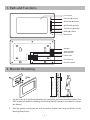
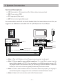
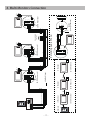
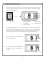
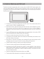
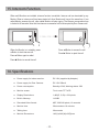
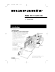
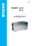
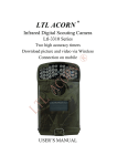
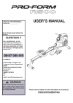
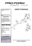
Video Intercom System
6910SD user manual
Tue.
ST-ENG-6910SD-V1 091S208
PRECAUTIONS
●● Read this manual through before using the product.
●● Slots or openings in the back of the monitor, are provided for ventilation
and to ensure reliable operation of the video monitor or equipment and
to protect if from overheating. These openings must not be blocked or
covered. The monitor should never be placed near or over a radiator or
heat register and should not be placed in a built-in installation such as a
bookcase unless proper ventilation is provided.
●● All parts should be protected from violence vibration. And not allow be
impacting, knocking and dropping.
●● For clean the LCD screen, using hands or wet cloth is forbidden.
●● Please do the cleanness with soft cotton cloth, please do not use the
organic or chemical clean impregnate. If necessary, please use pure
water or dilute soap water to clean the dust.
●● Image distortion may occur if the video door phone is mounted too close
to magnetic field e. g. Microwaves, TV, computer etc.
●● Please keep away the video door monitor from wet, high temperature,
dust, and caustic and oxidation gas in order to avoid any unpredictable
damage.
●● Do NOT open the device in any condition, call the administrator for help
if there is any problem or mulfunction happens.
CONTENT
1. Parts and Functions - - - - - - - - - - - - - - - - - - - - - - - - - - - - - - 1
2. Monitor Mounting- - - - - - - - - - - - - - - - - - - - - - - - - - - - - - - - 1
3. System Connection- - - - - - - - - - - - - - - - - - - - - - - - - - - - - - -2
4. Multi Monitors Connection- - - - - - - - - - - - - - - - - - - - - - - - - - 3
5. Multi Door Camera Connection - - - - - - - - - - - - - - - - - - - - - - 4
6. Monitor Operation Introduction- - - - - - - - - - - - - - - - - - - - - - - 5
7. Talk/Unlock Operation- - - - - - - - - - - - - - - - - - - - - - - - - - - - - 6
8. Ring Tone Setting- - - - - - - - - - - - - - - - - - - - - - - - - - - - - - - - 7
9. Monitor Time Setting- - - - - - - - - - - - - - - - - - - - - - - - - - - - - - 7
10. Time Setting- - - - - - - - - - - - - - - - - - - - - - - - - - - - - - - - - - - 8
11. Screen Setting - - - - - - - - - - - - - - - - - - - - - - - - - - - - - - - - - 8
12. Built-in Memory and SD Card - - - - - - - - - - - - - - - - - - - - - - 9
13. 1/2 Camera Setting- - - - - - - - - - - - - - - - - - - - - - - - - - - - - 11
14. Restore to Default- - - - - - - - - - - - - - - - - - - - - - - - - - - - - - 11
15. Intercom Function- - - - - - - - - - - - - - - - - - - - - - - - - - - - - - 12
16. Specifications- - - - - - - - - - - - - - - - - - - - - - - - - - - - - - - - - 15
1. Parts and Functions
LCD screen
UNLOCK(▲) button
MONITOR(▼) button
INTERCOM(●) button
TALK/PLAY(◄) button
MENU(►) button
Microphone
Speaker
Audio Handset
Slave Monitor
JS-AP
JS-VP
Power Input
DC-IN
JS-OS2 JS-OS1 LK VD
First Camera
Second Camera
145~160 cm
2. Monitor Mounting
1. Use the screws to fix the Mounting Bracket on the wall.(fitting accesories includes a Bracket (Two
4X25 screws are needed for fastening the Mounting Bracket), Special 4 core cables to connect
with Monitor)
2. Wire the system correctly(see the later connection chapter) then hang the Monitor on the
Mounting Bracket firmly.
-1-
3. System Connection
Terminal Discriptions:
●● 1R Power positive. +12V present when Door Station calling or being monitored
●● 2W Power negative (GND)
●● 3Y Image signal (Video signal)
●● 4B Talk and control signal (Audio signal)
It’s recommended to use RVVP 4x0.3mm2 Shielded Cable. And when distance is over 30m, we
suggest to use additional co-axle cable SYV- 75-3 (RG-59) connect 3Y and 2W pin.
AC ~
4B 2W +12
1R 2W 3Y 4B
Note 4
JS/AP
JS-OS2
JS_VP
LB
3 2 1
1R 2W 3Y 4B
DC- DC+
JS/VP
JS-OS1
CN101
1R 2W 3Y 4B 1R 2W 3Y 4B
Note 1
Note 2
Note 3
shielded layer
Black
Yellow
White
Red
●● Note 1: Plug the AC Adaptor in to the AC power terminal ensuring it is well seated.
●● Note 2: If you want to use multiple monitors: For a single Monitor system, keep the
jumper (which is already on JP-VD ). If you are setting up a multi-Monitor system, remove all JPVD jumpers EXCEPT the last Monitor. NB If you are setting up monitors PARALLEL rather than
chained, the ‘last’ monitor is the one physically furthest away from the door station.
●● Note 3: JP-LK is used to enable the electric Lock function. Remove the jumper if you are going to
use the Monitor power to supply power to the Lock. Refer to the Doorbell camera manual.
●● Note 4: LB port is for Lock connection, refer to Door Camera manual.
-2-
-34
PS
4
PS
JS-VD Reserved
N# Monitor
PS
OTHER EXTENDED
MONITORS
JS-VD
DC DC+
1R
2W
3Y
4B
1R
2W
3Y
4B
JS-LK
4B
2W
+12
1R
2W
3Y
4B
Back View
Black
Red
Red
White
Black
White
Extending Audio Phone:
JS/VP
JS-OS1
JS-VD Removed!
2# Monitor
shielded layer
JS-VD Removed!
JS-VD
JS/AP
JS-OS2
JS-VD Removed!
CN101
JS-VD Removed!
JS-VD
CN101
4
LB
JS_VP
DC DC+
GX-3P
4B
2W
+12
INSIDE
(90 Degree ROTATE)
JS-AP
JS-LK
JS-VD Reserved!
JS-VD
JS-LK
4B
2W
+12
1R
2W
3Y
4B
1R
2W
3Y
4B
Back View
1R
2W
3Y
4B
CN101
1# Monitor
1R
2W
3Y
4B
DC DC+
JS/VP
JS-OS1
JS-LK
1R
2W
3Y
4B
1R
2W
3Y
4B
JS/AP
JS-OS2
DC DC+
1R
2W
3Y
4B
4B
2W
+12
JS/VP
JS-OS1
JS-LK
1R
2W
3Y
4B
JS/VP
JS-OS1
Back View
AC ~
JS/AP
JS-OS2
Camera
1R 2W 3Y 4B
3 2 1
4B
2W
+12
Back View
JS/AP
JS-OS2
1R
2W
3Y
4B
AC ~
AC ~
4. Multi Monitors Connection
CN101
3 2 1
CN101
LB
JS_VP
1# Camera
-41# Camera
2# Camera
4
4
JS-LK
DC DC+
PS
4
JS-VD Removed!
2# Monitor
PS
4
OTHER EXTENDED
MONITORS
JS-LK
DC DC+
JS-VD Reserved
N# Monitor
PS
JS-VD Reserved!
JS-VD
4B
2W
+12
1R
2W
3Y
4B
Back View
AC ~
NOTE: When connect two Outdoor Stations, 1/2 Camera item should
be set to 2 on the FRIST Monitor. (Menu-setup-Advanced Set-1/2Camera)
JS-VD Removed!
1# Monitor
JS-VD Removed!
JS-VD
CN101
JS-VD Removed!
DC DC+
1R
2W
3Y
4B
1R
2W
3Y
4B
JS/VP
JS-OS1
JS-VD
1R
2W
3Y
4B
1R
2W
3Y
4B
1R
2W
3Y
4B
4B
2W
+12
JS/AP
JS-OS2
JS-LK
1R
2W
3Y
4B
1R
2W
3Y
4B
4B
2W
+12
Back View
JS/VP
JS-OS1
Back View
AC ~
JS/AP
JS-OS2
CN101
1R 2W 3Y 4B
1R 2W 3Y 4B
1R
2W
3Y
4B
AC ~
JS/VP
JS-OS1
LB
JS/AP
JS-OS2
JS_VP
3 2 1
2# Camera
5. Multi Door Camera Connection
6. Monitor Operation Introduction
In this Monitor, all the icons on the screen has a corresponding button, and each button has a
corresponding LED indicator; the LED indicator also has a state-sencitive feature for easy operation.
setup
When the screen showing the menus, press
the corresponding buttons to enter the sub
menu.
monitor
intercom
play
exit
Ooutdoor Tone
-- 01
When the screen showing the item which
have variable setting values, press the
corresponding buttons to increase the value
in sequence.
Intercom Tone -- 05
Monitor Time
-- 2min
Advanced Set...
Exit
When the screen showing operation icons,
press the corresponding buttons to execute
the operation.
rec
-5-
7. Talk/Unlock Operation
1. When visitor presses the Call Button on the Outdoor Station, the monitor rings, at the same
time, the screen displays the visitor image. A 10 second video will be recorded automatically
.after the Call Button pressed.
1
2
3
4
5
rec
1. Unlock icon/button
4. Talk icon/button.
2. Exit icon/button
5. Setting icon/button.
3. Record icon/button
2. Press TALK/PLAY ◄ Button, you can talk with the visitor for 90 seconds. During talking state,
press the TALK/PLAY ◄ Button again to end the conversation. If nobody answers the phone,
the screen will be turned off automatically after 30 seconds. If the system connects two or more
Monitors, when any Monitor starts to talk, the other Monitors will be automatically shut off.
3. During the conversation, press UNLOCK ▲
Button to unlock the door.
rec
4. During the conversation, press INTERCOM
● Button to record the current video(10
seconds).
-6-
rec
8. Ring Tone Setting
9. Monitor Time Setting
15 pieces ring tone can be selected. When
Monitor Time is the maximum monitoring
the Monitor is in standy, press ► Button, a
time when the MONITOR ▼ Button is
full screen calendar will be showed.
pressed in standby, after which the screen
will be closed automatically.
1
When the Monitor is in standy, press ►
Button to open the screen.
Tue.
Tue.
2
1. Current time.
3
2. Current date.
3. Current weekday.
Press ► Button to enter the main menu, press Press ►Button to enter the main menu.
► Button again to select and enter Setup
Press ▲Button to enter Setup menu.
menu.
setup
monitor
setup
intercom
monitor
play
intercom
exit
play
exit
Press ▲Button to select next Outdoor Tone
oin sequence, Press ▲Button to select next
Press ● Button in sequence to modify the
Intercom Tone in sequence.
Ooutdoor Tone
-- 01
Intercom Tone
-- 05
Monitor Time
-- 2min
Monitor Time.
Ooutdoor Tone
-- 01
Intercom Tone
-- 05
Monitor Time
-- 2min
Advanced Set...
Advanced Set...
Exit
Exit
Settings will be performed immediately,
Settings will be performed immediately,
press ►Button to exit.
press ►Button to exit.
-7-
10. Time Setting
11. Screen Setting
When the Monitor is in standby, press ►
When the Monitor is in monitoring or talking,
Button to open the screen, press ► Button
Press ► Button to open the screen setting
again to enter the main menu. Then press
menu.
▲Button to enter Setup menu, press ◄
Button to enter Advanced Set item.
rec
Ooutdoor Tone
-- 01
Intercom Tone
-- 05
Monitor Time
-- 2min
Advanced Set...
Exit
There are 4 setting items can be adjusted:
Screen Mode: Normal, Soft, Bright
and User. Different mode has different
Press ▼Button to enter Date/Time Set item
1/2 Camera
brightness and colour value.
Ratio: Can be set to 16:9 or 4:3.
-- 1
Ring Volume: For ring tone volume adjust.
Date/Time Set...
Information...
Talk Volume: For talk volume adjust.
Exit
Normal
16:9
Ring Volume 5
Use the ▲Button / ▼ Button to increase /
Talk Volume 8
Exit
decrease the current number, press ● Button
to confirm and switch to next digit.
When the screen mode was switched to
User mode, press ◄ Button / ● Button to set
the Brightness and Colour independently.
TIME 1 1 : 3 5
DATE 2 0 0 9 0 3 3 1
: Modify Digit
: Next Digit
: ESC
User
When all numbers have been input, the
Brightness
5
Colour
6
Exit
setting will be save automatically and exit, or
press ◄ Button to quit.
-8-
12. Built-in Memory and SD Card
This Monitor has been equipped with a buit-in memory (about 118 MB, 50 ASF videos) together with
a SD card reader. Maximum 2 GB SD card can be supported. When a new SD card was inserted
to the Monitor, the SD card will be formated to FAT32 file system and 2 file folder(named DCIM and
PHOTO) will be created.
SD card
●● This Monitor can play back JPEG photos and ASF videos. The recorded videos will be
saved in the SD--> DCIM-->100MEDIA file folder.
●● Photo frame function, each photo playing will last 5 seconds, it will be stopped in one hour.
More pictures in the SD card, longer time for triggering the fuction, less than 1000pcs is
recommend. Note that the Monitor can only play back the photos in the SD-->PHOTO file
folder.
●● Only the JPEG photos took by a digital camera can be played back in this monitor, JPEG
picture processed by other software might not be supported.
●● Please do not play back pictures with the file size over 30MB.
●● This Monitor can record ASF videos, both manually and automatically, the durantion of the
ASF video is fixed in 10 seconds.
●● When there is a SD card in the Monitor, the recording ASF videos will be saved in the SD
card firstly; they will be saved in the built-in memory when the SD card is full.
●● The ASF videos in the built-in memory can be copy to the SD card.
●● The built-in memory and SD card can be formated by the Monitor.
●● Avoid plug in/out the SD Card when the monitor is under operation, it may cause the
death of memory board, please exit all operation when it is happened, and the device will
automatically reset in 30seconds( no need for restart the power), in the process, the LED
will turn to Green from Red.
●● Please do not play back pictures with the file size over 30MB;
●● The play back will be interupted by the calling from outdoor station.
-9-
When the Monitor is in standby or the Main
setup
monitor
menu is open, press ◄ Buttton to enter PLAY
intercom
menu.
play
exit
1. Play back photos
2. Play back videos
1
2
3
4
5
3. Copy videos from built-in memory to SD card
(SD-->DCIM-->101MEDIA folder)
4. Memory information
5. Exit
When playing videos, there is no sound at first,
press the TALK/PLAY Button to play the sound.
1
2
3
4
5
1. Play back last photo/video
2. Play back next photo/video
3. Delete currrent photo/video
4. Enter screen setting Menu
5. Exit
1. Used built-in memory
FLASH:
1%
VIDEO:
3
SD CARD:
5%
PHOTO:
21
VIDEO:
18
1
2
3
4
5
2. ASF videos in built-in memory
3. Used SD card memory
4. Photos in SD card(PHOTO folder)
5. ASF videos in SD card(100MEDIA folder)
6. Under this screen, press and hole the
INTERCOM (●) Button for 3 seconds, a DEL
FLASH & SD ? hit will be showed on the
screen, press the UNLOCK Button to execute
the formating, press any other key to exit
without execution.
-10-
13. 1/2 Camera Setting
14. Restore to Default
When 2 Door Cameras are installed, the 1/2
The restore to default function allows the
Camera mode should be set to 2. Default is
user to recover the settings to factory setting.
set to 1 for only one Camera.
Note that the restore to default operation will
When the Monitor is in standby, press ►
not change the time setting and the files on
the buit-in momery or SD card.
Button to open the time screen, press ►
When the Monitor is in standby, press ►
Button again to enter the main menu, then
Button to open the time screen, press again
press ▲Button to enter Setup menu.
to enter the main menu. press ▲Button to
enter Setup menu, then press Advanced
setup
Set item.
monitor
intercom
play
exit
1/2 Camera
-- 1
Date/Time Set...
Information...
Press ◄ Button to enter Advanced Set item.
Ooutdoor Tone
Exit
-- 01
Intercom Tone
-- 05
Monitor Time
-- 2min
In the Information menu, press Restore
to default item, the default settings will be
Advanced Set...
Exit
loaded. press Exit to exit out the menu.
H/W ver A1.1
Press ▲ Button to toggle the 1/2 Camera
item between 1 and 2.
S/W ver V8.0
Voltage
15.8V
Manufacture
DM 1
Restore to default
Exit
1/2 Camera
-- 1
Date/Time Set...
Settings will be performed immediately,
Information...
press ►Button to exit.
Exit
Settings will be performed immediately,
press ►Button to exit.
-11-
15. Intercom Function
When multi Monitors are installed, intercom function is available. Intercom call can be started by any
Monitor. When a intercom call has been started, all other Monitors will ring at the same time, if one
called Monitor answers the call, other called Monitor will stop ringing. The intercom conversation time
is limited to 90 seconds. Note that the intercom conversation will be interrupted by Door Camera call.
Redial
TALK
EXIT
EXIT
When the Monitor is in standby, press
● Button to start intercom call.
Press ◄ Button to answer the call.
Press ►Button to reject the call.
Press ● Button again to redial.
Press ►Button to cancel the call.
16. Specifications
●● Power supply for indoor monitor: DC 16V (supplied by Adaptor)
●● Power supply for Door Camera:
DC 12V 500mA
●● Power consumption:
Standby 0.5W; Working status 15W
●● Monitor screen:
7 Inch color TFT-LCD
●● Display Resolutions:
1,440(R, G, B) x 234 pixels
●● Built-in Memory:
118 MB
●● Recorded Video format:
ASF, 320*240 pixels, 10 seconds
●● Monitor time:
30 seconds to 10 minutes
●● Talking time:
30 seconds
●● Monitor Dimensions:
143(H)×242(W)×23(D)mm
-12-
The design and specifications can be changed without notice to the user.
Right to interpret and copyright of this manual are preserved.
ST-ENG-6910SD-V1 091S208