1
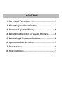
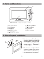
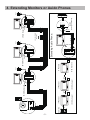
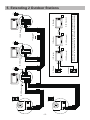
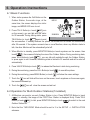
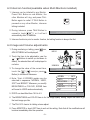
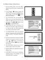
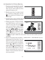
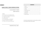
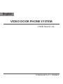
English
VIDEO DOOR PHONE SYSTEM
USER MANUAL
VT-ENG-6912-V1.1 090S603
CONTENT:
1. Parts and Functions ------------------------------1
2. Mounting and Installation----------------------1
3. Standard System Wiring-------------------------2
4. Extending Monitors or Auido Phones---------3
5. Extending 2 Outdoor Stations------------------4
6. Operation Instructions---------------------------5
7. Precautions-----------------------------------------9
8. Specifications--------------------------------------9
1. Parts and Functions
1
2
3
4
5
6
7
9
8
Dimensions: 160(H)×223(W)×25(D)
1. LCD Touch Screen
6. ( ) UNLOCK Button
2. Loud Speaker
7. ( ) CALL Button
3. TALK Button
8. Microphone
4. ( ) MENU Button
9. MESG Indicator
5. ( ) MONITOR Button
2. Mounting and Installation
1. Use the screws to fix the Mounting
Bracket on the wall.(fitting accesories
includes a Bracket (Two 4X25 screws
are needed for fastening the Mounting
Bracket), Special 4 core cables to
connect with Monitor)
2. Wire the system correctly(see the later
connection chapter) then hang the
Monitor on the Mounting Bracket firmly.
3. Test the system untill it works properly.
-1-
3. Standard System Wiring
Terminal Discriptions:
●● 1R Power positive. +12V present when Door Station calling or being monitored
●● 2W Power negative (GND)
●● 3Y Image signal (Video signal)
●● 4B Talk and control signal (Audio signal)
It’s recommended to use RVVP 4x0.3mm2 Shielded Cable. And when distance is over
30m, we suggest to use additional co-axle cable SYV- 75-3 (RG-59) connect 3Y and 2W
pin.
AC ~
4
* Note 2
* Note 3
2
3
1R
2W
3Y
4B
1R
2W
3Y
4B
4B
2W
+12
Black
Yellow
Red
White
1R
2W
3Y
4B
DCDC+
1R
2W
3Y
4B
Black
1R
2W
3Y
4B
Yellow
1
1R
2W
3Y
4B
LB
JS/AP
JS-OS2
Red
JP-LK
* Note 4
JS/VP
JS-OS1
White
CN101
JP-VD
JS-VP
* Note 1
Back View
●● Note 1: Plug the AC Adaptor to the AC power socket properly.
●● Note 2: JP-VD is used for setting the video impedance. When there is only one Monitor,
keep the jumper (which is already on JP-VD ). But when multi Monitors are installed, be
sure of taking away all JP-VD of Monitors except only the last Monitor.
●● Note 3: P-LK is used for Lock selection, remove the jumper if use the Monitor power to
supply the Lock. Refer to the Outdoor station manual.
●● Note 4: LB includes 3 wiring Terminals: ‘1’-Normally Opened Terminal, ‘2’- Common
Terminal, ‘3’- Normally Closed Terminal. If the Lock is activated when powering, connect it
between ‘1’ and ‘2’ terminal; if the Lock is activated when power-off, connect it between ‘2’
and ‘3’ terminal.
-2-
1R
2W
3Y
4B
-3-
4
JP-VD Removed!
4
PS
PS
1R
2W
3Y
4B
4
JP-VD Removed!
2# Monitor
JS/AP
JS-OS2
1# Monitor
LB
Back View
JS/VP
JS-OS1
1R
2W
3Y
4B
JP-LK
4B
2W
+12
1R
2W
3Y
4B
DCDC+
JP-VD Reserved
N# Monitor
PS
1R
2W
3Y
4B
1R
2W
3Y
4B
JP-LK
JP-VD
Back View
4B
2W
+12
1R
2W
3Y
4B
DCDC+
AC ~
OTHER EXTENDED
MONITORS
JP-VD Reserved!
JS/VP
JS-OS2
JS-OS1
1R
2W
3Y
4B
CN101
1R
2W
3Y
4B
JP-LK
JP-VD
4B
2W
+12
1R
2W
3Y
4B
DCDC+
Back View
Black
Red
Red
White
Black
White
Extending Audio Phone:
JP-VD Removed!
JS/AP
JS-OS2
Camera
Black
JP-VD
JS/VP
JS-OS1
Red
Back View
GX-3P
4B
2W
+12
4B
2W
+12
1R
2W
3Y
4B
DCDC+
INSIDE
(90 Degree ROTATE)
JS-AP
1R
2W
3Y
4B
JP-LK
1R
2W
3Y
4B
JP-LK
JP-VD
JS/AP
JS-OS2
White
CN101
JS/VP
JS-OS1
Yellow
CN101
1
2
3
CN101
JS-VP
JP-VD Removed!
AC ~
AC ~
4. Extending Monitors or Auido Phones
JS/AP
White
Red
JS-VP
1R
2W
3Y
4B
Yellow
-4-
JS-VP
2#
LB
LB
JP-VD Removed!
Black
Back View
1R
2W
3Y
4B
1R
2W
3Y
4B
JP-LK
JP-VD
JS/AP
JS-OS2
1R
2W
3Y
4B
JS/VP
JS-OS1
Red
4
4
1R
2W
3Y
4B
JP-VD Removed!
PS
PS
Back View
4B
2W
+12
1R
2W
3Y
4B
DCDC+
JP-VD Reserved
N# Monitor
1R
2W
3Y
4B
1R
2W
3Y
4B
JP-LK
JP-VD
PS
NOTE: When connect two Outdoor Stations, 1WAY/2WAY Mode should
be set to 2 on the FRIST Monitor. (Menu-setup-installation-1way/2way)
JP-VD Removed!
2# Monitor
OTHER EXTENDED
MONITORS
JP-VD Reserved!
4
4B
2W
+12
1R
2W
3Y
4B
DCDC+
AC ~
4
Back View
1R
2W
3Y
4B
JP-LK
JP-VD
1# Monitor
JP-VD Removed!
1# Camera
2# Camera
4B
2W
+12
1R
2W
3Y
4B
DCDC+
AC ~
JS/AP
JS-OS2
Black
JS/VP
JS-OS1
White
CN101
JS/AP
JS-OS2
Yellow
CN101
JS/VP
JS-OS1
1
2
3
CN101
1
2
3
1#
AC ~
5. Extending 2 Outdoor Stations
6. Operation Instructions
6.1 Basic Functions
1. When visitor presses the Call Button on the
Outdoor Station, the monitor rings, at the
same time, the screen displays the visitor
image, and MESG LED turns to red.
2. Press TALK Button(or touch TALK icon
on the screen), you can talk with the visitor
for 90 seconds. During talking state, press
IMG 16
TALK
EXIT
rec
03
2009/02/14
10:30
H o m e I n t e l l eg e n t S y s t e m
TALK Button (or touch TALK )again to end
the conversation. If nobody answers the phone, the screen will be turned off automatically
after 30 seconds. If the system connects two or more Monitors, when any Monitor starts to
talk, the other Monitors will be automatically shut off.
3. When Monitor is standby, press MONITOR Button(or touch anywhere on the screen, then
touch monitor ), the screen will display the view of the Outdoor Station. During monitoring state,
press TALK Button(or touch TALK ), you can talk with outside through the Outdoor Station,
or press again to exit. However, monitoring state is limited to 30 seconds and will be shut off
automatically.
4. Press UNLOCK Button(or touch
) to release the Electronic Latch during monitoring.
5. During the monitoring, press the CALL Button(or touch
rec
6. During the monitoring, press MENU Button (or touch
) to record the picture.
) will show the creen settings.
7. Touch the
icon will hide all the icons on the screen, touch anywhere on the screen again,
the icons will showed up.
8. Touch the
EXIT
icon will close the screen and exit out.
6.2 Operation for Multi Outdoor Stations(if installed)
1. All Monitors can monitor on each Outdoor Station in turn. Press MONITOR Button(or touch
monitor ) in standby, the image of the FIRST Door Station is displayed firstly. Press TALK
Button(or touch TALK ) to talk, press MONITOR Button(or touch monitor )to switch to the next
Outdoor Station etc.
2. Note that the 1WAY/2WAY Mode should be set to 2 in the SETUP --> INSTALLATION
submenu.
-5-
6.3 Intercom function(available when Multi Monitors installed)
1. Intercom can be initiated by any Monitor.
Press CALL Button on one Monitor, the
other Monitors will ring, and press CALL
Button again to redial. If TALK Button is
pressed on any other Monitor, intercom
talking is started.
Redial
EXIT
2. During intercom, press TALK Button to
cancel(or touch EXIT ), or it will exit
automatically after 30 seconds.
H o m e I n t e l l eg e n t S y s t e m
3. Intercom function is prior to monitor function, but calling function is always the first.
6.4 Image and Volume adjustments
1. During monitoring or talking, press
ADJUST MENU will be displayed.
icon,
2. Touch the item to be adjusted(or use the
/
Buttons to switch up and down to
select), the selected item will be displayed in
red color.
3. To change the value of the current item,
touch the
/
icons(or press
Button) to increase or decrease.
4. Note: Total 4 SCREEN modes can be
selected in sequence: NORMAL, USER,
SOFT and BRIGHT. Whenever you modify
BRIGHTNESS or COLOUR, SCENE item
will be set to USER mode automatically.
5. RATIO can be shifted from 16:9 to 4:3.
IMG 16
TALK
EXIT
rec
03
2009/02/14
10:30
H o m e I n t e l l eg e n t S y s t e m
SCREEN
RATIO
BRIGHTNESS
COLOR
TALK VOL
EXIT
------
SOTF
16:9
4
4
6
H o m e I n t e l l eg e n t S y s t e m
6. The BRIGHTNESS and COLOR item is for the image quality setting, adjust the value to get
the best image you like.
7. The TALK VOL item is for talking volume adjust.
8. Press MONITOR or touch EXIT item to exit out the setting, Note that all the modifications will
be done immediately after the operation.
-6-
6.5 Basic Setup Instructions
1. During standby state, press the MENU
Button(or touch the screen) to display MAIN
MENU.
2. Press the
/
Buttons to select the
SETUP item, then press the MENU Button
again to enter. (or touch the setup icon to
enter SETUP MENU)
3. The OUTDOOR CALL and INTERCOM
CALL item are for chord ring selection, the
RING VOLUME item is for ring volume
adjustment. Press
/
Button(or touch
/
) to increase/decrease.
4. If the AWAY SET item is turned on, the
Monitor will record the image automatically
in 2 seconds after the visitor pressed the
CALL Button on the Outdoor station.
5. The INSTALLATION...item is for advance
settings. a password will be asked before
enter the setting. The defoult password is
2008.
6. Input the password by touching the digital
keypad on the screen to enter.(or you can
press
/
Buttons to change the
current digit, and press
Button to shift to
the next one)
7. The 1WAY/2WAY should be set to 2 if 2
Outdoor stations were to be installed.
8. UNLOCK TIME will be adjusted according to
different locks.
9. INFORMATION will show the hardware/
software version and voltage info. the
ADVANCED SET is reserved.
-7-
play
monitor
intercom
setup
exit
H o m e I n t e l l eg e n t S y s t e m
DOOR CALL
-- 01
INTERCOM CALL -- 05
RING VOLUME -- 06
INSTALLATION...
AWAY SET
-- OFF
EXIT
H o m e I n t e l l eg e n t S y s t e m
Password: 0
***
1
2
3
4
5
*
H o m e I n t e l l eg e n t S y s t e m
1WAY/2WAY
-- 1
UNLOCK TIME -- 3
DATE/TIME SET...
ADVANCED SET...
INFORMATION
EXIT
H o m e I n t e l l eg e n t S y s t e m
6
7
8
9
0
#
6.6 Operation for Picture Memory
1. The picture can be recorded both manually
and automatically. The image capacity is
above 120 pcs, and the oldest one will be
replaced if the memory is full.
play
monitor
2. Manually record: when the screen is turned
on, in monitoring or talking state, touch the
icon (or press the CALL Button) to save
current image.
intercom
setup
exit
rec
H o m e I n t e l l eg e n t S y s t e m
3. Automatic record: enter the SETUP page and turn on the AWAY SET item. Then the MESG
indicator LED will be flashing in Green color.
4. Playback the pictures: During the standby,
press MENU Button(or touch the screen)
to enter the main menu, then touch
icon(or use the Buttons to select) to enter
the playback page. The latest picture will be
IMG 16
DELETE?
LAST
play
show. touch NEXT / LAST icon(or press
the
/
) to view forward / backward.
Touch the DELE? icon, a 'DELETE?' hint will
show on the uper right of the screen, Touch
NEXT
DELE?
EXIT
2009/02/14
10:30
H o m e I n t e l l eg e n t S y s t e m
the DELE? icon again to delete the current picture. Please note that the delete operation is
irrepeatable.
5. Date and Time setting: Enter the SETUP --> INSTALLATION --> DATE/TIME SET item, the
setting page will show as bellow. Touch the
keypad on the screen to input the numbers.
1 6
Or you can input the number by the Buttons:
:
1
1
3
5
2 7
TIME
Press the
/
Buttons to change the
3 8
current number(which indicated by a up
DATE 2 0 0 9 0 2 1 4
4 9
arrow), press the Button to switch to the
5 0
next number. (if input by Buttons, it will save
: CANCEL
:
OK
#
*
* #
and exit automatically after input all the
H o m e I n t e l l eg e n t S y s t e m
numbers. If input by the screen, touch the #
icon to save and exit)
-8-
7. Precautions
●● All parts should be protected from violence vibration. And not allow be
impacting, knocking and dropping.
●● For clean the Lens& Screen, using hands or wet cloth is forbidden.
●● Please do the cleanness with soft cotton cloth, please do not use the organic or
chemical clean impregnate. If necessary, please use a little pure water or dilute
soap water to clean the dust.
●● Image distortion may occur if the video door phone is mounted too close to
magnetic field e. g. Microwaves, TV, computer etc.
●● Please keep away the video door monitor from wet, high temperature, dust,
and caustic and oxidation gas in order to avoid any unpredictable damage.
8. Specifications
●● Power supply for indoor monitor: DC 15~18V (supplied by Adaptor)
●● Power supply for Door Station:
DC 10~12V (Supplied by Indoor Monitor)
●● Audio Phone :
DC 10~12V (Supplied by Indoor Monitor)
●● Power consumption:
Standby 0.5W; Working status 15W (for kits)
●● Monitor screen:
7 Inch color TFT-LCD
●● Display Resolutions:
1,440(R, G, B) x 234 pixels
●● Video signal:
1Vp-p, 75Ω, CCIR standard
●● Pictures saved:
127 PCS
●● Connection mode:
4 wiring, polar
●● Monitor time:
30 seconds
●● Talking time:
90 seconds
●● Dimensions:
160(H)×223(W)×25(D)
-9-
The design and specifications can be changed without notice to the
user. Right to interpret and copyright of this manual are preserved.
VT-ENG-6912-V1.1 090S603