1
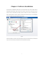
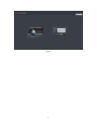
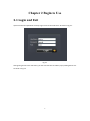
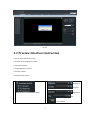
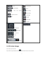
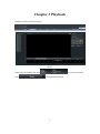
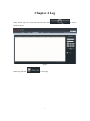
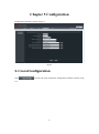
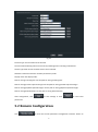
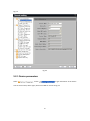
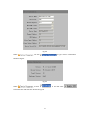
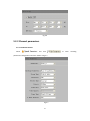
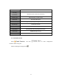
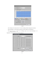
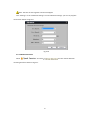
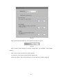
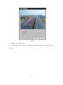
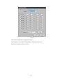
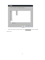
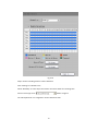
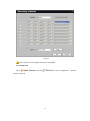
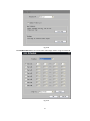
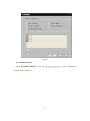
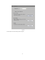
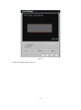
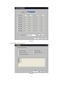
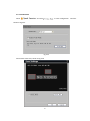
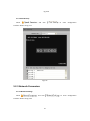
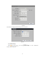
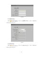
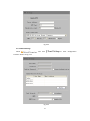
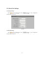
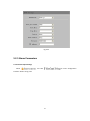
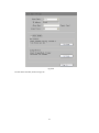
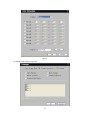
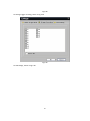
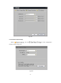
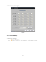
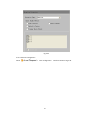
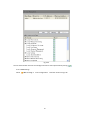
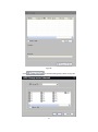
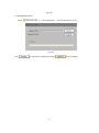
User Manual of Web Client (V2.3) Index Chapter 1 Software Installation......................................................................................................... 1 Chapter 2 Begin to Use ..................................................................................................................... 3 2.1 Login and Exit ...................................................................................................................... 3 2.2 Preview Interface Instruction .............................................................................................. 4 2.3 Preview Image ..................................................................................................................... 5 Chapter 3 Playback ........................................................................................................................... 6 Chapter 4 Log ................................................................................................................................... 7 Chapter 5 Configuration.................................................................................................................... 8 5.1 Local Configuration ............................................................................................................. 8 5.2 Remote Configuration ......................................................................................................... 9 5.2.1 Device parameters ................................................................................................. 10 5.2.2 Channel parameters ............................................................................................... 12 5.2.3 Network Parameters .............................................................................................. 28 5.2.4 Serial Port Settings ................................................................................................. 32 5.2.5 Alarm Parameters................................................................................................... 33 5.2.6 Other Settings ........................................................................................................ 38 Chapter 1 Software Installation This web client is embedded in DVR, when you use web browser to get access to DVR, it will be downloaded automatically. Please decrease the internet security level to make sure that the ActiveX could be downloaded successfully. Open IE browser and select as following steps: ToolsInternet optionssecurityinternetcustom level. As shown in Fig 1.1. In the setting list you should enable all the options about ActiveX control. Fig 1.1 Input the IP address or domain name of DVR and press enter, the interface like Fig 1.2 will pop up. If you can see the interface, the ActiveX has been downloaded successfully. 1 Fig 1.2 2 Chapter 2 Begin to Use 2.1 Login and Exit Input username and password correctly to get access to the web client. As shown in Fig 2.1. Fig 2.1 After getting access to the web client, you can click exit then click OK in pop-up dialog box to exit. As shown in Fig 2.2. 3 Fig 2.2 2.2 Preview Interface Instruction 1. Device name and channel name 2. Function and configuration column 3. PTZ control column 4. Image adjustment column 5. Function column 6. Preview mode column 1 4 :Brightness :Contrast :Saturation Device name and channel name :Hue : Color default 4 2 5 : Preview : Remote Playback : Local and : Stop All Preview : Capture Remote : Start recording Configuration : Stop recording : Log Search and View : Previous page : Exit :Next page : Audio On/Off : Full screen 3 6 Preview mode options :PTZ direction :light & wiper : Zoom in & out : Focus : Iris :Preset 2.3 Preview Image Step 1 Select a preview mode. Step 2 Select one split window and click before channel name to start to preview. 5 Chapter 3 Playback Playback interface is shown as Fig3.1. Fig 3.1 Select channel and date ,then click Click to search record files. to download record files. 6 Chapter 4 Log Select search type, start time and stop time then click Shown as fig 4.1. Fig 4.1 Select logs and click to save logs. 7 to search. Chapter 5 Configuration Configuration interface is shown as Fig 5.1. Fig 5.1 5.1 Local Configuration Click to enter the local parameters configuration interface. Shown as Fig 5.2. 8 Fig 5.2 Protocol Type: TCP and UDP can be selected. The Size of File Packeting: Select the size of file packeting when recording via web client Stream Type: Main stream and Sub stream can be selected. Network Transmission Feature: Set delay and fluency mode. Display mode: Set display mode. Path for saving recording files: Set the path for saving recording files. Path for saving preview captured images: Set the path for saving preview captured images Path for saving playback captured images: Set the path or saving playback captured images Path for saving download files: Set the path or saving download files After configuration, click to save settings or click to reset local parameters. 5.2 Remote Configuration Click to enter the remote parameters configuration interface. Shown as 9 Fig 5.3. Fig 5.3 5.2.1 Device parameters Select and click to get information of the device such as device name, device type, device serial NO etc. shown as Fig 5.4. 10 Fig 5.4 Select and click to get version information. Shown as Fig 5.5. Fig 5.5 Select and click to set DST. Click to fill start time and end time. Shown as Fig 5.6. 11 Fig 5.6 5.2.2 Channel parameters 5.2.2.1 Video Parameters Select and click parameters configuration interface. Shown as Fig 5.7. Fig 5.7 12 to enter encoding Parameters Description Encoding Main/Sub stream and Event Parameters Parameters Stream Type Video & Audio or Video stream Resolution Recording Resolution Video Quality Highest, higher, high, average, lower, lowest Bitrate Type Variable & Constant Max Bitrate Maximum bit rate of the compressed stream Frame Rate Record frame rate, from 1/16 to full frame Frame Type BBP,BP & Single P frame I frame interval The interval between 2 I frames 5.2.2.2 Schedule Record Select and click interface. Shown as Fig 5.8. Enable recording by clicking the tick . 13 to enter configuration Fig 5.8 Click “Settings” of the “Record Time” to enter recording schedule configuration interface. Select “Weekday” as some day of the week or the whole week for recording time. Click for the recording type. The “All Day Recording” or 8 “Segments” can be selected as well. Shown as Fig 5.9. Fig 5.9 14 Note: The time of each segment can’t be overlapped. Click “Settings” of the “Advanced settings” to enter advanced settings. you can set pre/post record time. Shown as Fig 5.10. Fig 5.10 5.2.2.3 Motion Detection Select and click to enter motion detection recording interface. Shown as Fig 5.11. 15 Fig 5.11 Step 1: Select channel number for motion detection. Shown as Fig 5.12 Fig 5.12 Step 2: Enable motion detection to activate “Setting Area”, “Arm Schedule” and “Linkage” settings. Step 3: Set the motion detection area and sensitivity. The sensitivity 1 and 6 are the lowest and the highest level. Enable “Start Draw”, and select the detection area by using mouse. Shown as Fig 5.13 16 Fig 5.13 Step4: Set the detection time. “Arm Schedule” can be one day or the whole week, and 8 segments for one day. Shown as Fig 5.14 17 Fig 5.14 Step5: Set recording channel triggered by alarm. Click “Settings” in “Linkage” menu and select “Trigger Recording” tab. Enable the recording channels you want. 18 Fig 5.15 Step6: Enter schedule recording interface. Click Shown as 5.16 19 to enable Recording. Fig 5.16 Step7: Set the recording time for motion detection. Click “Settings” of “Record Time”. Select “Weekday” as some day of the week or the whole week for recording time. Set the record type to be . Shown as Fig 5.17 The “All Day Record” or 8 “Segments” can be selected as well. 20 Fig 5.17 Note: The time of each segment can not be overlapped. 5.2.2.4 Video Lost Select and click to enter configuration Shown as Fig 5.18. 21 interface. Fig 5.18 Click Enable Video Lost to set arm schedule and linkage. Shown as Fig 5.19 and 5.20. Fig 5.19 22 Fig 5.20 5.2.2.5 Video Tampering Select and click interface. Shown as Fig 5.21. 23 to enter configuration Fig 5.21 Set the tamper area and sensitivity, shown as Fig 5.22. 24 Fig 5.22 Set the arm schedule, shown as Fig 5.23. 25 Fig 5.23 Set the linkage, shown as Fig 5.24. Fig 5.24 26 5.2.2.5 Video Mask Select and click to enter configuration Shown as Fig 5.25. Fig 5.25 Set the video mask area, shown as Fig 5.26. 27 interface. Fig 5.26 5.2.2.6 Text Overlay Select and click to enter configuration interface. Shown as Fig 5.27. Fig 5.27 5.2.3 Network Parameters 5.2.3.1 Network Settings Select and click interface. Shown as Fig 5.28. 28 to enter configuration Fig 5.28 Click Advance to configure advanced settings. Shown as Fig 5.29. Fig 5.29 5.2.3.2 PPPOE Settings Select and click interface. Shown as Fig 5.30. 29 to enter configuration Fig 5.30 5.2.3.3 DDNS Settings Select and click to enter configuration interface. Shown as Fig 5.31. Fig 5.31 5.2.3.4 NTP Settings Select and click interface. Shown as Fig 5.32. 30 to enter configuration Fig 5.32 5.2.3.5 Email Settings Select and click interface. Shown as Fig 5.33. Fig 5.33 31 to enter configuration 5.2.4 Serial Port Settings 5.2.4.1 RS-232 Settings Select and click to enter configuration interface. Shown as Fig 5.34. Fig 5.34 5.2.4.2 RS-485 Settings Select and click interface. Shown as Fig 5.35. 32 to enter configuration Fig 5.35 5.2.5 Alarm Parameters 5.2.5.1 Alarm Input Settings Select and click to enter configuration interface. Shown as Fig 5.36. 33 Fig 5.36 Set the alarm schedule, shown as Fig 5.37. 34 Fig 5.37 Set linkage mode, shown as Fig 5.38 35 Fig 5.38 Set linkage trigger recording, shown as Fig 5.39. Fig 5.39 Set PTZ linkage, shown as Fig 5.40. 36 Fig 5.40 5.2.5.12 Alarm Output Settings Select and click to enter configuration interface. Shown as Fig 5.41. Fig 5.41 37 Set alarm schedule, shown as Fig5.42. Fig 5.42 5.2.6 Other Settings 5.2.6.1 Exception parameters Select to enter configuration 38 interface. Shown as Fig 5.43. Fig 5.43 5.2.6.2 Account management Select to enter configuration 39 interface. Shown as Fig 5.44. Fig 5.44 You can add or delete accounts and configure account’s IP and permission by ticking 5.2.6.3 HDD Settings Select to enter configuration 40 interface. Shown as Fig 5.45. . Fig 5.45 Click to attribute HDD groups, shown as Fig 5.46. 41 Fig 5.46 5.2.6.4 Update Remotely Select to enter configuration interface. Shown as Fig 5.47. Fig 5.47 Click to find path for update file and click 42 to start updating.