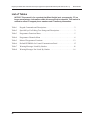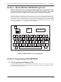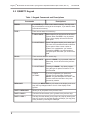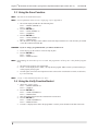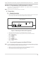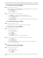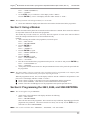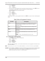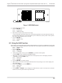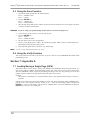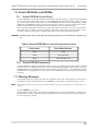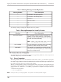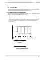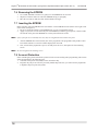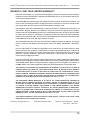
1
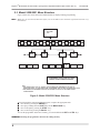
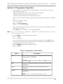
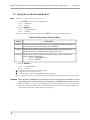
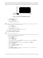
REGENCY
Model 5520 and 5521
Desk Top Programmer
Operational Manual
Part Number 150479, Rev. A
Initial Release Date: August 1990
Revised May 1998
NOTICE: This manual is for a product that Silent Knight (and, consequently, ITI) no longer manufactures. Information within this manual
may be obsolete. This manual is revised to reflect ITI support phone
numbers and ITI warranty information.
Interactive Technologies, Inc.
2 2 6 6
S e c o n d S t r e e t N o r t h
N o r t h S a in t P a u l , M N
5 5 1 0 9 - 2 9 0 0
T : 6 5 1 / 7 7 7 - 2 6 9 0
F : 6 5 1 / 7 7 9 - 4 8 9 0
TE C H N O L O G IE S
Security
Automation
Fire Protection
Access Control
ITI and Regency are registered trademarks of Interactive Technologies, Inc.
ITI © 1998. All rights reserved.
For reprints, order manual:
150479, Revision A
Regency® Model 5520 and 5521 Desk Top Programmer Operational Manual (P/N 150479, Rev. A) Revised 5/98
FCC Notices
FCC Part 15 Information to the User
Changes or modifications not expressly approved by Interactive Technologies, Inc. can void the user’s
authority to operate the equipment.
FCC Part 15 Class B
This equipment has been tested and found to comply with the limits for a Class B digital device, pursuant
to part 15 of the FCC Rules. These limits are designed to provide reasonable protection against interference in a residential installation.
This equipment generates, uses, and can radiate radio frequency energy and, if not installed and used in
accordance with the instructions, may cause harmful interference to radio communications. However,
there is no guarantee that interference will not occur in a particular installation.
If this equipment does cause harmful interference to radio or television reception, which can be determined
by turning the equipment off and on, the user is encouraged to try the correct the interference by one or
more of the following measures:
■ Reorient or relocate the panel’s receiving antenna.
■ Increase the separation between the equipment and receiver.
■ Connect the affected equipment and the panel receiver to separate outlets, on different branch
circuits.
■ Consult the dealer or an experienced radio/TV technician for help.
FCC Part 68
This equipment complies with part 68 of the FCC Rules. Located on this equipment is a label that contains,
among other information, the FCC registration number and the ringer equivalence number (REN) for this
equipment. If requested, this information must be provided to the telephone company.
The REN is used to determine the maximum number of devices that may be connected to your telephone
line. In most areas, the sum of all device RENs should not exceed five (5.0).
If this equipment causes harm to the telephone network, the telephone company may temporarily disconnect your service. If possible, you will be notified in advance. When advance notice is not practical, you
will be notified as soon as possible. You will also be advised of your right to file a complaint with the FCC.
Your telephone company may make changes in its facilities, equipment, operations, or procedures that
could affect the proper operation of your equipment. You will be given advance notice in order to maintain
uninterrupted service.
If you experience trouble with this equipment, please contact the company that installed the equipment for
service and repair information. The telephone company may ask you to disconnect this equipment from
the network until the problem has been corrected or you are sure that the equipment is not malfunctioning.
This equipment may not be used on coin service provided by the telephone company. Connection to party
lines is subject to state tariffs.
i
Regency® Model 5520 and 5521 Desk Top Programmer Operational Manual (P/N 150479, Rev. A) Revised 5/98
Table of Contents
NOTICE: This manual is for a product that Silent Knight (and, consequently, ITI) no
longer manufactures. Information within this manual may be obsolete. This manual
is revised to reflect ITI support phone numbers and ITI warranty information.
Section 1 Model 5520/5521 EEPROM Programmer . . . . . . . . . . . . . . . . . . . . . . . . . .1
Section 2 Programming 2816 EEPROMs . . . . . . . . . . . . . . . . . . . . . . . . . . . . . . . . . . . .1
2.1 The Liquid Crystal Display (LCD) . . . . . . . . . . . . . . . . . . . . . . . . . . . . . . .1
2.2 QWERTY Keypad . . . . . . . . . . . . . . . . . . . . . . . . . . . . . . . . . . . . . . . . . . . .2
2.3 Model 5520/5521 Menu Structure . . . . . . . . . . . . . . . . . . . . . . . . . . . . . . . .4
Section 3 Programmer Operation . . . . . . . . . . . . . . . . . . . . . . . . . . . . . . . . . . . . . . . . . .5
3.1 Using the Load Function/Socket . . . . . . . . . . . . . . . . . . . . . . . . . . . . . . . . .6
3.2 Using the Edit Function . . . . . . . . . . . . . . . . . . . . . . . . . . . . . . . . . . . . . . . .7
3.3 Using the Save Function . . . . . . . . . . . . . . . . . . . . . . . . . . . . . . . . . . . . . . .8
3.4 Using the Verify Function/Socket . . . . . . . . . . . . . . . . . . . . . . . . . . . . . . . .8
Section 4 Programming a 2816 Installed in a Panel . . . . . . . . . . . . . . . . . . . . . . . . . . .9
4.1 Connections . . . . . . . . . . . . . . . . . . . . . . . . . . . . . . . . . . . . . . . . . . . . . . . . .9
4.1.1 Standard Connections . . . . . . . . . . . . . . . . . . . . . . . . . . . . . . . . . . . . .9
4.1.2 Connecting the Programmer to the Model 2750 Panel . . . . . . . . . . .9
4.2 Using the Load Function/XBUS . . . . . . . . . . . . . . . . . . . . . . . . . . . . . . . .10
4.3 Using the Edit Function / XBUS . . . . . . . . . . . . . . . . . . . . . . . . . . . . . . . .10
4.4 Using the Save Function/XBUS . . . . . . . . . . . . . . . . . . . . . . . . . . . . . . . .10
4.5 Using the Verify Function/XBUS . . . . . . . . . . . . . . . . . . . . . . . . . . . . . . .10
Section 5 Using a Modem . . . . . . . . . . . . . . . . . . . . . . . . . . . . . . . . . . . . . . . . . . . . . . . .11
Section 6 Programming the 2443, 2444, and 9346 EEPROMs . . . . . . . . . . . . . . . . . .11
6.1 Using the Load Function . . . . . . . . . . . . . . . . . . . . . . . . . . . . . . . . . . . . . .12
6.2 Using the Edit Function . . . . . . . . . . . . . . . . . . . . . . . . . . . . . . . . . . . . . . .13
6.3 Using the Save Function . . . . . . . . . . . . . . . . . . . . . . . . . . . . . . . . . . . . . .14
6.4 Using the Verify Function . . . . . . . . . . . . . . . . . . . . . . . . . . . . . . . . . . . . .14
Section 7 Appendix A . . . . . . . . . . . . . . . . . . . . . . . . . . . . . . . . . . . . . . . . . . . . . . . . . . .14
7.1 Loading/Saving a Single Page (2816) . . . . . . . . . . . . . . . . . . . . . . . . . . . .14
7.2 Default EEPROMs and EPROMs . . . . . . . . . . . . . . . . . . . . . . . . . . . . . . .14
7.2.1 Default EEPROM (Control Panel) . . . . . . . . . . . . . . . . . . . . . . . . . .14
7.2.2 Default EPROM (Programmer) . . . . . . . . . . . . . . . . . . . . . . . . . . . .15
7.3 Warning Messages . . . . . . . . . . . . . . . . . . . . . . . . . . . . . . . . . . . . . . . . . . .15
7.4 Connection to a Computer . . . . . . . . . . . . . . . . . . . . . . . . . . . . . . . . . . . . .16
7.4.1 Direct Connection . . . . . . . . . . . . . . . . . . . . . . . . . . . . . . . . . . . . . . .16
7.4.2 Using the XBUS . . . . . . . . . . . . . . . . . . . . . . . . . . . . . . . . . . . . . . . .17
7.5 Software Updates and Replacement . . . . . . . . . . . . . . . . . . . . . . . . . . . . .17
7.6 Removing the EPROM . . . . . . . . . . . . . . . . . . . . . . . . . . . . . . . . . . . . . . .18
7.7 Inserting the EPROM . . . . . . . . . . . . . . . . . . . . . . . . . . . . . . . . . . . . . . . . .18
7.8 Account Protection . . . . . . . . . . . . . . . . . . . . . . . . . . . . . . . . . . . . . . . . . . .18
ii
Regency® Model 5520 and 5521 Desk Top Programmer Operational Manual (P/N 150479, Rev. A) Revised 5/98
List of Figures
NOTICE: This manual is for a product that Silent Knight (and, consequently, ITI) no
longer manufactures. Information within this manual may be obsolete. This manual
is revised to reflect ITI support phone numbers and ITI warranty information.
Figure 1
Model 5520 Desk Top Programmer . . . . . . . . . . . . . . . . . . . . . . . . . . . . . . . . .1
Figure 2
Model 5520/5521 Menu Structure . . . . . . . . . . . . . . . . . . . . . . . . . . . . . . . . . .4
Figure 3
Placement of EEPROM in Socket . . . . . . . . . . . . . . . . . . . . . . . . . . . . . . . . . .7
Figure 4
Connecting the Cable to the Programmer . . . . . . . . . . . . . . . . . . . . . . . . . . . . .9
Figure 5
EEPROM Socket . . . . . . . . . . . . . . . . . . . . . . . . . . . . . . . . . . . . . . . . . . . . . .13
Figure 6
EPROMs U6 and U7 . . . . . . . . . . . . . . . . . . . . . . . . . . . . . . . . . . . . . . . . . . . .17
iii
Regency® Model 5520 and 5521 Desk Top Programmer Operational Manual (P/N 150479, Rev. A)
Revised 5/98
List of Tables
NOTICE: This manual is for a product that Silent Knight (and, consequently, ITI) no
longer manufactures. Information within this manual may be obsolete. This manual is
revised to reflect ITI support phone numbers and ITI warranty information.
Table 1
Keypad Commands and Descriptions . . . . . . . . . . . . . . . . . . . . . . . . . . . . . . . .2
Table 2
Special Keys For Editing Text Strings and Descriptions . . . . . . . . . . . . . . . . .3
Table 3
Programmer Functions Menu . . . . . . . . . . . . . . . . . . . . . . . . . . . . . . . . . . . . . .5
Table 4
Programmer Channels Menu . . . . . . . . . . . . . . . . . . . . . . . . . . . . . . . . . . . . . .6
Table 5
Menu of Programmer Functions . . . . . . . . . . . . . . . . . . . . . . . . . . . . . . . . . . .12
Table 6
Default EEPROMs for Control/Communicator Panel . . . . . . . . . . . . . . . . . .15
Table 7
Warning Messages Listed By Number . . . . . . . . . . . . . . . . . . . . . . . . . . . . . .16
Table 8
Warning Messages Not Listed By Number . . . . . . . . . . . . . . . . . . . . . . . . . .16
iv
Regency® Model 5520 and 5521 Desk Top Programmer Operational Manual (P/N 150479, Rev. A)
Revised 5/98
Section 1: Model 5520/5521 EEPROM Programmer
NOTICE: This manual is for a product that Silent Knight (and, consequently, ITI) no
longer manufactures. Information within this manual may be obsolete. This manual
is revised to reflect ITI support phone numbers and ITI warranty information.
The Model 5520/5521 Programmer can program the 2443, 2444, 9346, and 2816 EEPROMs (electrically
erasable programmable read-only memory). The 5520/5521 has a Liquid Crystal Display (LCD) and a standard keypad (one that spells “QWERTY” on the first six upper left keys). It is powered by an external plugin transformer and/or an internal 12-V battery (optional). The 2816 EEPROM can be programmed in the
socket, over the XBUS, or over the phone line using the Model 5530 Telephone Interface. Figure 1, “Model
and Desk Top Programmer,” is a representation of the Model 5520.
RST
SMALL
SOCKET
!
1
@
2
LARGE
SOCKET
$
4
#
3
W
Q
A
S
Z
SHIFT
CTRL
R
E
X
C
(
9
U
Y
G
V
*
8
&
7
T
F
D
^
6
%
5
LCD DISPLAY
J
H
B
I
N
M
:
;
L
<
,
STEP
BACK
P
O
K
+
=
` '
-
)
0
>
.
SPACE
ENTER
?
/
SHIFT
MENU
SKIP
8457G18A.DSF
Figure 1: Model 5520 Desk Top Programmer
Section 2: Programming 2816 EEPROMs
2.1 The Liquid Crystal Display (LCD)
The LCD is divided into two lines: the first (top) line of the display describes the current step that is being
programmed; the second (bottom) line shows the current step data. Since each line can hold only 16 characters, some words will be abbreviated.
1
Regency® Model 5520 and 5521 Desk Top Programmer Operational Manual (P/N 150479, Rev. A)
Revised 5/98
2.2 QWERTY Keypad
Table 1: Keypad Commands and Descriptions
Commands
ENTER
The ENTER key is used to store data in memory. This key must
be pressed before moving to the next option, if you want the data
to be stored in memory.
STEP→
There are two ways to use this key:
BACK←
2
Descriptions
1. MENU MODE
Menu steps let you choose one of the list of
options. When the STEP→ key is pressed,
Line 2 of the display will scroll to the next
data option.
2. Y/N OPTIONS
Some Y/N options require you to enter specific zone of ID numbers that will be affected
by the option. When a zone number is
entered, it is considered a “yes” answer.
Pressing the STEP→ key when programming this option will select “yes” for all of the
data.
There are three ways to use this key:
1. MENU MODE
When the BACK← key is pressed, while at a
Menu step, Line 2 will scroll to the previous
choice.
2. Y/N OPTIONS
Pressing the BACK← key when programming this type of options will select “no” for
all of the data.
3. DATA
OPTIONS
If you are programming an option that
requires you to enter data, pressing the
BACK← key will backspace the cursor. This
function would be used when a key was
pressed by mistake.
MENU SKIP
Pressing the MENU SKIP key will advance the display to the next
step, but any changes made to Line 2 of the display will be
ignored.
SHIFT + MENU SKIP
Allows you to jump back to the previous menu.
SHIFT + BACK←
The Back Function allows you to go back to the previous step.
SHIFT + STEP→
The Step Function allows you to jump to any step by entering the
step #. If you are in a step that has many substeps, you may jump
to any of these by entering the substep #.
Regency® Model 5520 and 5521 Desk Top Programmer Operational Manual (P/N 150479, Rev. A)
Revised 5/98
Table 2: Special Keys For Editing Text Strings and Descriptions
Commands
Descriptions
CTRL + E
This will ERASE ALL of the words in the section that is being edited.
There are three sections where this feature may be used:
Messages 0-31,
Messages 32-63, and
Locations 1-80.
After pressing CTRL and E at the same time, the display will ask you
if you want to erase all words. Press Y for yes and N for no.
CTRL + P
This will pack together all the used words, freeing up any unused
words or characters. It will also display the amount of free character
space in that section.
CTRL + F
This will display the number of unused (free) characters in either the
Messages section or the Locations section.
SEMI-AUTOMATIC
PACKET
The programmer will automatically pack when the “FULL” message is
displayed.
Example: You want to change the message “INTRUSION” to “BURGLARY.” The LCD says “FULL!” because there isn’t room to add 8
characters in the word “burglary.” Press ENTER to see how much
free space is available. Then, press the space bar and reenter the
word “BURGLARY.”
CTRL + RST
This will reset the programmer completely. The data stored in memory will be erased.
3
Regency® Model 5520 and 5521 Desk Top Programmer Operational Manual (P/N 150479, Rev. A)
Revised 5/98
2.3 Model 5520/5521 Menu Structure
Figure 2 shows the various menus and submenus that are displayed during programming.
NOTE
Make sure you use the Load Function before you use the Edit or Save Functions (explained in Section 3 of
this manual).
REV XXXXX
5521
1
1420
5107
1520
VERIFY
XBUS
MODEM
SOCKET
2750
HEX
5207
2
LOAD
XBUS
1501
2820
SOCKET
ETC.
SAVE
EDIT
MODEM
2730
XBUS
MODEM
SOCKET
PROGRAMMABLE OPTIONS- THESE VARY AMONG
DIFFERENT CONTROL/COMMUNICATOR MODELS
8457G08A.DSF
NOTES
1. MODEL NUMBERS WITHIN A GRAY BOX DESIGNATE CONTROL/COMMINICATORS PROGRAMMED WITH THE MODEL 2816
EEPROM (LARGE SOCKET); ALL OTHER MODELS SHOWN ARE PROGRAMMED USING THE MODEL 2444 EEPROM (SMALL SOCKET).
2. MODEL NUMBERS AND PROGRAMMABLE OPTIONS MAY VARY BETWEEN THE 5520 AND 5521, AND BETWEEN DIFFERENT
SOFTWARE REVISIONS.
Figure 2: Model 5520/5521 Menu Structure
To move through the menu and submenu structure, complete the appropriate task:
■ move down by pressing the ENTER key,
■ move up by holding down the SHIFT key and the MENU SKIP key,
■ move to the right by pressing the STEP→ key,
■ move to the left by pressing the BACK← key,
To reset the programmer and clear its memory, press and hold both the RST and CTRL keys.
WARNING! Resetting the programmer will clear the editing memory.
4
Regency® Model 5520 and 5521 Desk Top Programmer Operational Manual (P/N 150479, Rev. A)
Revised 5/98
Section 3: Programmer Operation
1.
If your programmer is not equipped with a rechargeable battery, you must connect the power transformer provided (see Figure 3).
a) Plug the transformer cable into the power connector on the programmer.
b) Plug the transformer into a 120-VAC , 60-Hz wall outlet.
c) Turn on the power switch located on the back of the programmer.
This menu covers two different models of programmers. They are identified as Model 5520 and Model
5521.
The display will appear as follows:
Line 1 = “REV DATE”
Line 2 = “5520 PROGRAMMER”
OR Line 2 = “5521 PROGRAMMER”
This is the first menu of the programmer. The revision level may be different, depending upon when the
programmer was purchased.
Use the STEP→ key to scroll Line 2 to show “PROGRAMMER.”
NOTE
Line 2 can be scrolled to show “TERMINAL,” “RECEIVER,” and “XBUS TEST.” However, these three
items are for factory test use only.
2.
3.
Press the ENTER key. The display will appear as follows:
Line 1 = “MODEL”
Line 2 = “(MODEL #)”
This is a menu of the models that can be programmed with the programmer. Use the STEP→ key to
scroll through the numbers, until you reach the correct one. The following example demonstrates the
procedure for panels using 24-pin 2816-type devices.
Press the ENTER key. The display will appear as follows:
Line 1 = “(MODEL #)”
Line 2 = “LOAD”
Table 3: Programmer Functions Menu
Option
LOAD
Description
Will load the internal memory of the programmer from a previously programmed EEPROM.
CAUTION! Always load before editing or attempting to save
data.
EDIT
Allows you to change the options in the internal memory of the
programmer.
SAVE
Will save the internal memory of the programmer into an
EEPROM.
VERIFY
Will compare am EEPROM with the internal memory of the
programmer.
NOTE
“Verify” is done automatically when you “Save.”
5
Regency® Model 5520 and 5521 Desk Top Programmer Operational Manual (P/N 150479, Rev. A)
Revised 5/98
3.1 Using the Load Function/Socket
NOTE
You must use “Load” before “Edit” and “Save.”
1.
2.
Use the STEP→ key to select the Load Function.
Line 1 = “(MODEL #)”
Line 2 = “LOAD”
Press the ENTER key.
Line 1 = “LOAD (MODEL #)”
Line 2 = “SOCKET”
Below is a menu of programmer channels. Use the STEP→ key to scroll through the options:
Table 4: Programmer Channels Menu
Option
Description
SOCKET
Allows you to load the internal memory of the programmer with the data stored
in a previously programmed (master) 2816 EEPROM.
XBUS
Allows you to load the programmer internal memory by connecting the programmer directly to the Expansion Bus (XBUS) of the panel.
MODEM
Allows you to load the programmer internal memory using the 5530 Modem
and a remotely located panel.
Line 1 = “LOAD (MODEL #)”
Line 2 = “SOCKET”
3.
Press the ENTER key.
Line 1 = “LOAD (MODEL #)”
Line 2 = “SOCKET”
The Load Function can be used in two different ways:
■ to load one “page” of data at a time or
■ to load the entire contents of the EEPROM into the programmer.
Refer to Appendix A (Section 7.1) of this manual for an explanation and instructions on single page loading.
CAUTION! Before handling an EEPROM, you should touch a static discharge pad, located under the small
programming socket. This will reduce the risk of damage to the EEPROM from static electricity.
4.
5.
6
Make sure that the lever on the large programming socket is in the up position before inserting the chip.
Place a previously programmed (master) 2816 chip in the large socket on the programmer, making sure
that the notch on the chip is towards the lever (see Figure 3).
Regency® Model 5520 and 5521 Desk Top Programmer Operational Manual (P/N 150479, Rev. A)
Revised 5/98
8457G09A.DS4
Figure 3: Placement of EEPROM in Socket
6.
7.
8.
NOTE
Lower the lever on the socket.
Press the ENTER key.
Line 1 = “LOAD (MODEL #)”
Line 2 = “REMOVE 2816”
Raise the lever and remove the 2816.
A copy of the data in the Master 2816 is now stored in the programmer. The stored data will remain in the
programmer, until power is removed from the system.
Press the ENTER key.
Line 1 = “LOAD (MODEL #)”
Line 2 = “SOCKET”
10. You may want to “Edit” some options.
11. When done editing, “Save” this information into a new 2816.
9.
3.2 Using the Edit Function
NOTE
You must use the Load Function first.
In this mode, you will step through the options and program them as needed. An explanation of each option
will be found in the installation manual for each model.
Line 1 = “MODEL (MODEL #)”
Line 2 = “EDIT”
1. Press the ENTER key.
Line 1 = “EDIT (MODEL #)”
Line 2 = “SYSTEM OPTS.”
2. At this point, you may either press the ENTER key to edit the system options or use the STEP→ key to
see other categories that may be edited.
3. When all of your choices have been made, press both the SHIFT key and the MENU key.
Line 1 = “EDIT (MODEL #)”
Line 2 = “SYSTEM OPTS.”
4. Press both the SHIFT and the MENU keys again.
Line 1 = “ MODEL (MODEL #)”
Line 2 = “EDIT”
5. Use the STEP→ or BACK← key to change Line 2, until it shows “SAVE.” You can use the Save
Function to store the options on a 2816.
7
Regency® Model 5520 and 5521 Desk Top Programmer Operational Manual (P/N 150479, Rev. A)
Revised 5/98
3.3 Using the Save Function
NOTE
You must use the Load Function first.
NOTE
For an explanation on how to save a single page, refer to Appendix A.
1.
2.
3.
4.
The current display should show the following lines:
Line 1 = “MODEL (MODEL #)”
Line 2 = “SAVE”
Press the ENTER key.
Line 1 = “SAVE (MODEL #)”
Line 2 = “SOCKETS.”
Press the ENTER key.
Line 1 = “SAVE (MODEL #)”
Line 2 = “INSERT 2816.”
Place the 2816 in the large socket with the notch of the chip toward the lever. The 2816 may be a blank
or one that contains unwanted data.
CAUTION! If you are using a programmed 2816, you will lose all data on it.
5.
6.
NOTE
Programming the 2816 takes up to 21 seconds. The programmer will beep once it has finished programming.
7.
8.
9.
NOTE
Lower the lever on the socket to secure the chip in place.
Press the ENTER key.
Line 1 = “PASS”
Line 2 = “REMOVE 2816.”
The 2816 in the socket is now programmed.
If Line 1 of the display shows “FAIL,” the chip did not program. Make sure that you followed the procedure properly and try again.
If it fails again, remove the 2816 chips and reseat it in the socket. If it still does not work, it is defective;
try a new 2816 chip.
“Verify” is done automatically when you “Save.”
3.4 Using the Verify Function/Socket
1.
2.
3.
4.
5.
8
Choose the “Verify” menu.
Line 1 = “MODEL (MODEL #)”
Line 2 = “VERIFY”
Press the ENTER key.
Line 1 = “VERIFY (MODEL #)”
Line 2 = “INSERT 2816”
Insert the 2816 as described in the Load Function section above.
Press the ENTER key.
Line 1 = “VERIFY (MODEL #)”
Line 2 = “REMOVE 2816”
If “FAIL” is displayed, the data in the programmer’s memory is not identical to the data in the 2816.
Regency® Model 5520 and 5521 Desk Top Programmer Operational Manual (P/N 150479, Rev. A)
Revised 5/98
Section 4: Programming a 2816 Installed in a Panel
The procedure for programming installed EEPROMs is only slightly different from programming
EEPROMs in the programming socket.
NOTE
The panel must be in a programming mode to use the XBUS.
4.1 Connections
4.1.1
1.
2.
Standard Connections
Turn off the programmer and panel.
Connect one end of the 12-wire double ended cable (provided) to the XBUS connector on the programmer (see Figure 4). The XBUS wires should extend down from the connector slot.
MODEL 5520 REAR VIEW
ON
XBUS
MODEM
POWER
OFF
PIN 1
PIN 1 (BROWN WIRE)
8457G10A.DS4
Figure 4: Connecting the Cable to the Programmer
3.
4.
5.
6.
Connect the other end of the cable to one of the XBUS connectors on the panel.
Only apply power to the control panel. (The programmer will be powered from the XBUS.)
Line 1 = “REV 870514”
Line 2 = “PROGRAMMER”
Press the ENTER key.
Line 1 = “MODEL”
Line 2 = “(MODEL #)”
Press the ENTER key again.
Line 1 = “MODEL (MODEL #)
Line 2 = “LOAD”
4.1.2
NOTE
Connecting the Programmer to the Model 2750 Panel
To connect the Model 2750 Control/Communicator to the Model 5521 Desk Top Programmer, you must use
the 7-wire cable adaptor (P/N 130295-- 7-pin connector on one end, 12-pin connector on the other) instead
of the 12-wire double ended cable described in the previous section.
1.
2.
3.
Plug the 12-pin connector to the XBUS (12-pin connector) on the back of the programmer.
Connect the other end of the cable to header H3 on the 2750 circuit board.
Once all connections have been made, apply power to the 2750.
9
Regency® Model 5520 and 5521 Desk Top Programmer Operational Manual (P/N 150479, Rev. A)
Revised 5/98
4.2 Using the Load Function/XBUS
NOTE
You must use the Load Function first.
At this time, you may either “Load” data from a master 2816 in the programming socket (see 2816 programming) or from the 2816 installed in the control panel.
1. Press the ENTER key.
Line 1 = “LOAD (MODEL #)”
Line 2 = “SOCKET”
NOTE
In this example we will load from the (Model #) XBUS.
2.
3.
4.
Use the STEP→ key to scroll Line 2 of the display to show “XBUS.”
Press the ENTER key. Approximately 5 to 10 seconds later, the display will show
Line 1 = “LOAD (MODEL #)”
Line 2 = “REMOVE 2816”
If the display doesn’t show “FAIL,” a copy of the data in the 2816 located in the panel matches the data
stored in the programmer.
4.3 Using the Edit Function / XBUS
NOTE
You must use the Load Function first.
The Editing procedure is identical to the explanation in Section 3.2 of this manual.
4.4 Using the Save Function/XBUS
NOTE
You must use the Load Function first.
1.
2.
3.
NOTE
Make sure that the 12-conductor cable is connected to the programmer and the (Model #).
4.
5.
NOTE
Find the “SAVE” menu.
Line 1 = “MODEL (MODEL #)”
Line 2 = “SAVE”
Press the ENTER key.
Line 1 = “SAVE (MODEL #)”
Line 2 = “SOCKET”
Use the STEP→ key to scroll Line 2 of the display to show “XBUS.”
Press the ENTER key.
Line 1 = “SAVE (MODEL #)”
Line 2 = “REMOVE 2816”
If no FAIL condition is displayed, the data stored in the programmer has been programmed into the
2816, which is located on the panel.
“VERIFY” is done automatically when you “SAVE.”
4.5 Using the Verify Function/XBUS
NOTE
You must use the Load Function first.
1.
2.
10
Find the “VERIFY” menu.
Line 1 = “MODEL (MODEL #)”
Line 2 = “VERIFY”
Press the ENTER key.
Regency® Model 5520 and 5521 Desk Top Programmer Operational Manual (P/N 150479, Rev. A)
3.
NOTE
Revised 5/98
Line 1 = “VERIFY (MODEL #)”
Line 2 = “SOCKET”
Use the STEP→ key to scroll Line 2 of the display to show “XBUS.”
Press the ENTER key. Line 2 of the display will show either “PASS” or “FAIL.”
The Verify Function will take approximately 5 to 10 seconds.
4.
If no FAIL condition is displayed, the data in the 2816 matches the data stored in the programmer.
Section 5: Using a Modem
Connect the modem to the phone line as described in the modem user’s manual. Then connect the modem to
the 10-position connector on the back of the programmer.
The modem may be used to load, save, and verify. Since the sequence of events is the same for all three
items, the example will show how to use the Load Function only.
Example:
1. After connecting the modem to the programmer, turn on the power.
Line 1 = “REV 870514”
Line 2 = “PROGRAMMER”
2. Press the ENTER key.
Line 1 = “MODEL”
Line 2 = “(MODEL #)”
3. Press the ENTER key again.
Line 1 = “MODEL (MODEL #)”
Line 2 = “LOAD”
4. Press the ENTER key again.
Line 1 = “LOAD (MODEL #)”
Line 2 = “ACCOUNT”
5. Enter the account number that is programmed in the panel as “Account #4” and press the ENTER key.
Line 1 = “LOAD (MODEL #)”
Line 2 = “WAITING”
6. At this point, someone must activate the “Request Download” feature of the panel. The panel will call
the programmer.
NOTE
The phone number of the line connected to the programmer must be programmed as the computer phone
number in the control/communicator panel before requesting download.
When the programmer answers, Line 2 of the display will show “PAGE.” When the Load operation is complete, Line 2 of the display will show “PASS” or “FAIL.”
■ If Line 2 shows “VOICE,” a call came, but it is not communicating with the programmer.
■ If Line 2 shows “ERROR,” a call came in, but the communication was interrupted.
■ If either of the above should happen, reset the programmer and repeat the procedure above.
Section 6: Programming the 2443, 2444, and 9346 EEPROMs
NOTE
This section applies to 8-pin EEPROMs.
1.
NOTE
Apply power to the programmer. The display will show the following:
Line 1 = “REV 870514”
Line 2 = “PROGRAMMER”
This is the first menu of the programmer. The revision level may be different, depending upon when the
programmer was purchased. These three items are for factory test use only. Use the STEP→ key to
scroll Line 2 to show “PROGRAMER.”
Line 2 can be scrolled to show “TERMINAL,” “RECEIVER,” and “SLOT TEST.”
11
Regency® Model 5520 and 5521 Desk Top Programmer Operational Manual (P/N 150479, Rev. A)
2.
3.
4.
Revised 5/98
Press the ENTER key.
Line 1 = “MODEL”
Line 2 = “(MODEL #)”
This is the menu of the models that can be programmed with the programmer. Use the STEP→ key to
scroll through the model numbers, until you reach the one you want to program.
The Model 2730 is used in the following examples.
Line 1 = “MODEL”
Line 2 = “2730”
Press the ENTER key.
Line 1 = “MODEL 2730”
Line 2 = “LOAD”
The following is a table of menu programmer functions. The STEP→ key may be used to scroll through the
options.
Table 5: Menu of Programmer Functions
Function
Description
LOAD
Will load the internal memory of the programmer from a previously programmed EEPROM. Always load before editing or
saving to a chip.
EDIT
Allows you to change the options stored in the memory of the
programmer.
SAVE
Will save the internal memory of the programmer into an
EEPROM.
VERIFY
Will compare an EEPROM with the internal memory of the programmer.
NOTE
“Verify” is done automatically when you “Save.”
6.1 Using the Load Function
1.
2.
Use the STEP→ key to select the Load Function.
Line 1 = “MODEL 2730
Line 2 = “LOAD”
Press the ENTER key.
Line 1 = “LOAD 2730”
Line 2 = “SOCKET”
When Line 2 shows “SOCKET,” you can load the internal memory of the programmer with the data stored
in a master EEPROM.
NOTE
The other four types of “Load” menus (XBUS, MODEM, etc.) cannot be used with the 8-pin EEPROMs.
CAUTION! Before handling an EEPROM, touch the static discharge pad, located under the small programming socket. This will reduce the risk of damage to the EEPROM from static electricity.
3.
12
Make sure the chip is close to the lever, as shown in Figure 5.
Regency® Model 5520 and 5521 Desk Top Programmer Operational Manual (P/N 150479, Rev. A)
Revised 5/98
8457G11A.DS4
Figure 5: EEPROM Socket
4.
5.
6.
7.
Lower the lever on the socket.
Press the ENTER key.
Line 1 = “LOAD 2730”
Line 2 = “REMOVE 2444”
Raise the lever on the socket and remove the chip.
A copy of the data in the master chip is now stored in the programmer. The stored data will remain in
the programmer until power is removed from the system. At this time you may want to “Edit” options,
then “Save” this information onto a new chip.
Press the ENTER key.
Line 1 = “MODEL 2730”
Line 2 = “EDIT”
6.2 Using the Edit Function
In this mode you will step through the options and program them as needed. An explanation of each option
will be found in the installation manual for each model. The current display should show the following lines:
Line 1 = “MODEL 2730”
Line 2 = “EDIT”
1. Press the ENTER key.
Line 1 = “EDIT 2730”
Line 2 = “CONTROL”
2. At this point, you may want to press the ENTER key to edit the control options
or use the STEP→ key to advance to the Dialer options.
3. When all of your choices have been made for the control options, Line 2 of the display will show
“CONTROL.” Press the STEP→ key.
Line 1 = “EDIT 2730”
Line 2 = “DIALER”
4. Press the ENTER key to Dialer options.
5. When you have viewed all of the options and made the necessary changes, Line 2 of the display will
show “DIALER.”
6. Press both the SHIFT key and the MENU key.
Line 1 = “EDIT 2730”
Line 2 = “DIALER”
7. Use the STEP→ or BACK← key to change Line 2 until it shows “SAVE.” You may now use the Save
Function to store the options on the chip in the socket.
13
Regency® Model 5520 and 5521 Desk Top Programmer Operational Manual (P/N 150479, Rev. A)
Revised 5/98
6.3 Using the Save Function
1.
2.
3.
The current display should show the following lines:
Line 1 = “MODEL 2730”
Line 2 = “SAVE”
Press the ENTER key.
Line 1 = “SAVE 2730”
Line 2 = “INSERT 2444”
Place the chip in the small socket, with the notch of the socket towards the lever. The chip may be blank
or one that contains unwanted data.
CAUTION! If you are using a programmed chip, all data will be overwritten in this process.
4.
5.
6.
7.
8.
NOTE
Lower the lever on the socket to secure the chip in place.
Press the ENTER key.
Line 1 = “PASS”
Line 2 = “REMOVE 2444”
The chip in the socket is now programmed.
If Line 1 of the display shows “FAIL,” the chip did not program. Make sure that you followed the programming procedure properly and try again.
If the chip fails again, then it is defective. Try another chip.
“Verify” is done automatically when you “Save.”
6.4 Using the Verify Function
The Verify Function is the same as for the 2816, except you will use an 8-pin EEPROM chip and the small
programming socket.
Section 7: Appendix A
7.1 Loading/Saving a Single Page (2816)
This feature can be used to “merge” options from multiple 2816 EEPROMs. When using this feature, you
may use the modem or XBUS. All programming must be done using the large socket on the programmer.
The 2816 EEPROM contains 8 pages of programing. Referring to the Hex Programming Form, the first
number of the hex address is the page that the particular option is located on.
Example:
The option for “Fast Restores” is located at address “$007.” This option is stored on Page 0 of the programmer.
Follow the directions in this manual for loading or saving data. When the display shows “INSERT 2816,”
press P. Line 2 of the display will show “PAGE (0-7) -” Enter the desired page number and press the
ENTER key. Line 2 of the display will again show “INSERT 2816.” Insert the EEPROM and press the
ENTER key to load or save a single page.
14
Regency® Model 5520 and 5521 Desk Top Programmer Operational Manual (P/N 150479, Rev. A)
Revised 5/98
7.2 Default EEPROMs and EPROMs
7.2.1
Default EEPROM (Control Panel)
A default EEPROM (electrically erasable programmable read-only memory) is shipped in the EEPROM
socket of each panel (Model 5207, 2820, etc.). This EEPROM contains the basic default values for setting
up a control panel. Always load the data from this EEPROM into memory before programming a blank
EEPROM. This EEPROM contains system messages that are essential to run the control panel. Once the
data has been loaded into the programmer, it may be changed to meet your particular needs.
If the original default program is lost for any reason, these chips can be used to recover the data. Insert the
appropriate chip (see Table 6) into the programmer and read the default values in the programmer’s memory. Then connect the programmer to the panel and read the values into the chip from the panel.
CAUTION! Install the 2896, 4799, or 5296 chips only into the programmer. Do not install these chips into panels.
Table 6: Default EEPROMs for Control/Communicator Panel
7.2.2
Chip Number
Panel Model Number
2896
2820
4799
4720 and 4721
6396
5207 through 5212
Default EPROM (Programmer)
A default EPROM (erasable programmable read-only memory) is supplied with each programmer (Model
5520 and 5521). The EPROM is different from the default EEPROM shipped with the panel, in that the
EPROM cannot be reprogrammed and must not be installed in a panel. However, you can load the data from
the EPROM into the programmer, then save the data onto an EEPROM, which you can subsequently install
in a panel.
7.3 Warning Messages
After loading and before saving panel data, the programmer will check certain options for valid data. If
invalid data is found, the display will show “WARNING X.” The number “X” indicates the type of error.
NOTE
The warning message does not prevent you from loading or saving, but it should be corrected before proceeding.
Press the ENTER key to proceed.
The programmer cannot detect some kinds of programming errors. It is also possible for a warning to be
invalid. When a warning is displayed, check the applicable section of the program. If the program appears to
be correct, ignore the warning.
15
Regency® Model 5520 and 5521 Desk Top Programmer Operational Manual (P/N 150479, Rev. A)
Revised 5/98
Table 7: Warning Messages Listed By Number
Warning Number
Error Description
1
Invalid data in the System Options
2
Invalid data in the Message Menu
3
No Code 0
4
Phone #1 invalid
5
N/A
6
N/A
The following warnings are displayed in English, instead of by number:
Table 8: Warning Messages Not Listed By Number
Warning
XXXX BAD FORMAT
Error Description
You attempted to load a 2816 chip is improperly formatted or is of the wrong model type. Load a default
chip that is known to be good and save the data onto
the “bad” chip before proceeding.
NOTE
“XXXX” is the model number of the system you
are programming, such as 2820 or 5207.
NOT LOADED
You have attempted to save data without first loading
a valid chip. Load a valid chip, then try again.
BAD CODE
The passcode you entered does not match the code
on the panel. On protected panels, you must know the
passcode to change options.
7.4 Connection to a Computer
The programmer may also be connected to a computer for programming EEPROMs, either using the Model
5525 Cable Adaptor or by connection to the XBUS.
7.4.1
Direct Connection
When using a Model 5520 or 5521 with Software Revision 880217 (or later), you can connect the programmer directly to the computer to program the EEPROM. This connection should be made using the Model
5525 Cable Adaptor, available from ITI. Connect one end of the cable to the modem port on the 5520. Connect the other end of the cable to the serial port on the computer.
When the “552X Programmer” Option is selected using the 5540 or 5541 software, the computer will verify
the connection to the programmer. If the programmer is not connect properly, the computer will display
“PROGRAMMER NOT RESPONDING.” If everything is operational, the computer will respond with two
options:
1. Load from the programmer.
2. Save to the programmer.
NOTE
16
Do not press any keys on the programmer. All operations are initiated from the computer.
Regency® Model 5520 and 5521 Desk Top Programmer Operational Manual (P/N 150479, Rev. A)
Revised 5/98
The operator selects the desired option and enters the account number to Save/Load. Progress messages are
displayed on the computer screen and on the programmer display.
7.4.2
Using the XBUS
You can also connect the programmer to the XBUS and program an EEPROM from the computer using the
programmer as an interface. The programmer must be powered up with the panel that is being programmed.
This is the same as saving/loading through the XBUS, as described in Section 4.
7.5 Software Updates and Replacement
From time to time, it will be necessary to update the programmer’s software. The following paragraphs
describe how to change the software EPROM in the programmer:
1. Turn off the power to the programmer and unplug the transformer.
2. Remove the four corner screws located on the bottom of the programmer. When removing these screws,
hold on to the cover and the base. Do not let the cover fall away from the base, as this could damage the
programmer’s cables.
3. Set the programmer in an upright position on the table.
4. Carefully lift the bottom of the cover to expose the battery and printed circuit board. (See Figure 6 for
the locations of U6 and U7). These EPROMs must be replaced with the EPROMs that contain the
updated software.
U6
U7
6
7
5
0
2
BATTERY
8457G12A.DSF
Figure 6: EPROMs U6 and U7
17
Regency® Model 5520 and 5521 Desk Top Programmer Operational Manual (P/N 150479, Rev. A)
Revised 5/98
7.6 Removing the EPROM
1.
2.
3.
Use a small, flat blade screwdriver to gently lever the EPROM out of its socket.
Slip the screwdriver under one end of the EPROM and pry it up slightly.
Place the screwdriver under the other end and finish removing it.
7.7 Inserting the EPROM
Before inserting each new EPROM, make sure that Pin 1 of the EPROM is located at the lower right corner
of the socket (see Figure 6).
1. Be sure to match the numbers on the EPROM (6 & 7) to the corresponding sockets.
2. Apply even pressure on each end of the pins of the EPROM, so that they go in squarely. Check to make
sure that all of the pins of the EPROM are correctly inserted into the socket.
NOTE
If any of the pins are accidentally bent, they may be straightened with a needle nose pliers.
3.
4.
NOTE
After the EPROMs have been inserted, turn on the programmer. The programmer will produce a short
tone and the software revision level will be displayed on the LCD.
Now, switch off the programmer’s power, carefully close the cover, and replace the four mounting
screws.
Do not overtighten the mounting screws.
7.8 Account Protection
Some of the Regency panels will feature protection from account stealing and reprogramming. This feature
affects programming in the following ways:
1. You must enter a password (usually Code 0) to load the chip.
2. Programs may only be saved to the previously loaded chip. Therefore, you cannot use the programmer
to duplicate chips for protected systems.
18
Regency® Model 5520 and 5521 Desk Top Programmer Operational Manual (P/N 150479, Rev. A)
Revised 5/98
REGENCY® ONE YEAR LIMITED WARRANTY
Interactive Technologies, Inc. (ITI) warrants that Regency products manufactured by ITI (Regency
Product) will be free from defects in material and workmanship for one (1) year from the date of purchase by the original purchaser.
This Limited Warranty extends only to the original purchaser and does not extend to consumers, end
users or other secondary purchasers of Regency Product. Consumers or end users should contact
their selling dealer as to the nature and extent of the dealer's warranty, if any.
ITI's obligation under this Limited Warranty is limited to the repair or replacement, at ITI’s option, of
any defective Regency Product at no additional charge. ITI reserves the right to replace Regency
Product under this Limited Warranty with new or remanufactured product. ITI will not be responsible
for labor costs of removal or reinstallation of Regency Product. The repaired or replaced Regency
Product is then warranted under the terms of this Limited Warranty for the balance of the term of this
Limited Warranty or for ninety (90) days, whichever is longer.
This Limited Warranty does not cover the ITI PC-based software products or batteries of any type
used in connection with Regency Product (please refer to the battery manufacturer’s warranty, if
any).
ITI is not responsible for conditions or applications over which ITI has no control. Defects or problems as a result of such conditions or applications are not the responsibility of ITI. Such conditions or
applications include normal wear and tear, catastrophe, fault or negligence of the user or the original
purchaser, improper installation, application, maintenance or use of Regency Product, or other
causes external to Regency Product.
If you have a warranty claim, please contact Customer Service at 1-800-777-4841 and request authorization to return the Regency Product. Customer Service will issue you a Return Merchandise Authorization (RAM) number. Return the Regency Product, freight prepaid, to ITI together with reference to
the RMA number and a written explanation setting forth the potential defect in reasonable detail.
THE ORIGINAL PURCHASER'S EXCLUSIVE REMEDY WITH RESPECT TO ANY AND ALL LOSSES OR
DAMAGES RESULTING FROM ANY CAUSE WHATSOEVER SHALL BE REPAIR OR REPLACEMENT,
AS SPECIFIED ABOVE. ITI SHALL IN NO EVENT BE LIABLE FOR ANY CONSEQUENTIAL OR INCIDENTAL DAMAGES, HOWEVER OCCASIONED, WHETHER BY NEGLIGENCE OR OTHERWISE. SOME
STATES DO NOT ALLOW THE EXCLUSION OR LIMITATION OF INCIDENTAL OR CONSEQUENTIAL
DAMAGES, SO THIS LIMITATION OR EXCLUSION MAY NOT APPLY TO YOU.
THE FOREGOING LIMITED WARRANTY IS IN LIEU OF ALL OTHER WARRANTIES, EXPRESS OR
IMPLIED, AND NO PERSON (INCLUDING ANY AGENT, DEALER OR REPRESENTATIVE OF ITI) IS
AUTHORIZED TO MAKE ANY REPRESENTATION OR WARRANTY CONCERNING REGENCY PRODUCT EXCEPT TO REFER ORIGINAL PURCHASERS TO THIS LIMITED WARRANTY. ANY IMPLIED
WARRANTIES (INCLUDING, WITHOUT LIMITATION, ANY IMPLIED WARRANTIES OF MERCHANTABILITY OR FITNESS FOR A PARTICULAR PURPOSE) ARE LIMITED TO THE DURATION OF THIS
LIMITED WARRANTY. SOME STATES DO NOT ALLOW LIMITATIONS ON HOW LONG AN IMPLIED
WARRANTY LASTS, SO THIS LIMITATION MAY NOT APPLY TO YOU.
THIS LIMITED WARRANTY GIVES YOU SPECIFIC LEGAL RIGHTS. YOU MAY ALSO HAVE OTHER
RIGHTS WHICH VARY FROM STATE TO STATE.
Interactive Technologies, Inc.
*
2266 Second Street North
*
North St. Paul, Minnesota 55109
Rev 10/97 - 466-1537
19
Regency® Model 5520 and 5521 Desk Top Programmer Operational Manual (P/N 150479, Rev. A)
Revised 5/98
Index
NOTICE: This manual is for a product that Silent Knight (and, consequently, ITI) no
longer manufactures. Information within this manual may be obsolete. This manual is
revised to reflect ITI support phone numbers and ITI warranty information.
A
account protection . .
Appendix A . . . . . .
F
. . . . . . . . . . . . . . . . . . . .18
. . . . . . . . . . . . . . . . . . . .14
C
channels menu . . . . . . . . . . . . . . . . . . . . . . . . .6
computers . . . . . . . . . . . . . . . . . . . . . . . . . . .16
connections
computers . . . . . . . . . . . . . . . . . . . . . . . .16
programmer . . . . . . . . . . . . . . . . . . . . . . . .9
programmer to 2750 Panels. . . . . . . . . . . . . .9
XBUS wiring . . . . . . . . . . . . . . . . . . . . . . .9
control panel, defaults . . . . . . . . . . . . . . . . . . .14
D
defaults
EEPROM (Control Panel) . . .
EEPROMs and EPROMs . . . .
EPROM (Programmer) . . . . .
programs . . . . . . . . . . . . . . .
troubleshooting chips . . . . . . .
descriptions, warning messages . . .
Desk Top Programmer, illustrated .
direct connections . . . . . . . . . . . .
. . . . . . . . . .14
. . . . . . . . . .14
. . . . . . . . . .15
. . . . . . . . . .15
. . . . . . . . . .16
. . . . . . . . . .16
. . . . . . . . . . .1
. . . . . . . . . .16
E
Edit Function . . . . . . . . .
EEPROM . . . . . . . . . . .
defaults . . . . . . . . . .
installed 2816 . . . . . .
loading and saving . .
placement, illustrated .
programming . . . . . .
socket, illustrated . . .
standard connections .
EPROM
defaults . . . . . . . . . .
inserting them . . . . .
removing them . . . . .
U6 and U7, illustrated
error messages . . . . . . . .
20
. . . . . . . . . . .7, 10, 13
. . . . . . . . . . . . . . . . .1
. . . . . . . . . . . . .14, 15
. . . . . . . . . . . . . . . . .9
. . . . . . . . . . . . . . . .14
. . . . . . . . . . . . . . . . .7
. . . . . . . . . . . . . .1, 11
. . . . . . . . . . . . . . . .13
. . . . . . . . . . . . . . . . .9
. . . . . . . . . . . . .14, 15
. . . . . . . . . . . . . . . .18
. . . . . . . . . . . . . . . .18
. . . . . . . . . . . . . . . .17
. . . . . . . . . . . . . . . .16
functions
Edit . . . . . . . . . . . . . . . . . . . . . . 7, 10, 13
Load . . . . . . . . . . . . . . . . . . . . . . 6, 10, 12
programmer functions . . . . . . . . . . . . . . . . 5
Save . . . . . . . . . . . . . . . . . . . . . . 8, 10, 14
Verify . . . . . . . . . . . . . . . . . . . . . 8, 10, 14
I
illustrations
connecting the cable to the programmer . .
EEPROM placement . . . . . . . . . . . . . .
EEPROM sockets . . . . . . . . . . . . . . . .
Model 5520 Desk Top Programmer . . . .
Model 5520/5521 menu structure . . . . . .
U6 an U7 EPROMs . . . . . . . . . . . . . . .
inserting, EPROMs . . . . . . . . . . . . . . . . . .
... 9
... 7
. . 13
... 1
... 4
. . 17
. . 18
K
keypads . . . . . .
keys, special . . .
....................... 2
....................... 3
L
LCDs . . . . . . . . . . . . . . . . . . . . . . . . . . . . . . 1
limited warranty . . . . . . . . . . . . . . . . . . . . . . 19
Load Function . . . . . . . . . . . . . . . . . . 6, 10, 12
loading, a single page . . . . . . . . . . . . . . . . . . . 14
M
menus
programmer channels . . . . . . . . . . . . . . . . . 6
programmer functions . . . . . . . . . . . . . 5, 12
structure . . . . . . . . . . . . . . . . . . . . . . . . . 4
messages . . . . . . . . . . . . . . . . . . . 3, 14, 15, 17
Model 5520/5521 menu structure . . . . . . . . . . . . 4
models
2443 and 2444 . . . . . . . . . . . . . . . . . . . . 11
2750 Panel . . . . . . . . . . . . . . . . . . . . . . . . 9
2816 EEPROM . . . . . . . . . . . . . . . . 1, 9, 14
2820 Panel . . . . . . . . . . . . . . . . . . . . 14, 15
2896 EEPROM . . . . . . . . . . . . . . . . . . . . 15
4720/4721 Panel . . . . . . . . . . . . . . . . . . . 15
Regency® Model 5520 and 5521 Desk Top Programmer Operational Manual (P/N 150479, Rev. A) Revised 5/98
4799 EEPROM . . . . . . . . . . . . . . . . . . . .15
5207 Panel. . . . . . . . . . . . . . . . . . . . . . . .14
5207 Panel to 5212 Panel . . . . . . . . . . . . . .15
5520 Desk Top Programmer . . . . . . . . . . . . .1
5520/5521 EEPROM Programmer . . . . . . . . .1
5520/5521 menu structure . . . . . . . . . . . . . .4
5520/5521 Programmer . . . . . . . . . .4, 15, 16
5525 Cable Adaptor . . . . . . . . . . . . . . . . .16
6396 EEPROM . . . . . . . . . . . . . . . . . . . .15
9346 EEPROMs . . . . . . . . . . . . . . . . . . . .11
troubleshooting chips . . . . . . . . . . . . . . . . .16
modems . . . . . . . . . . . . . . . . . . . . . . . . . . . .11
U
O
XBUS .
operating the programmer .
updating, software . . .
. . . . . . . . . . . . . . . . . . 17
V
Verify Function.
. . . . . . . . . . . . . . . . . 8, 10, 14
W
warning messages . . . . . .
warranty . . . . . . . . . . . .
wires, XBUS connections .
. . . . . . . . . . . . . . . 15
. . . . . . . . . . . . . . . 19
................ 9
X
. . . . . . . . . . . . . . . . . . . . . . . . . . 9, 17
. . . . . . . . . . . . . . . . .5
P
programmers
channels menu . . . . . . . . . . . . . . . . . . . . . .6
connections . . . . . . . . . . . . . . . . . . . . . . . .9
defaults . . . . . . . . . . . . . . . . . . . . . . . . . .15
EEPROM . . . . . . . . . . . . . . . . . . . . . . . . .1
functions menu . . . . . . . . . . . . . . . . . . .5, 12
menu structure . . . . . . . . . . . . . . . . . . . . . .4
Model 5520, illustrated . . . . . . . . . . . . . . . .1
operating . . . . . . . . . . . . . . . . . . . . . . . . . .5
programming
EEPROMs . . . . . . . . . . . . . . . . . . . . . .1, 11
programs, default . . . . . . . . . . . . . . . . . . . . . .15
protecting accounts . . . . . . . . . . . . . . . . . . . . .18
Q
QWERTY Keypads .
. . . . . . . . . . . . . . . . . . . . .2
R
removing EPROMs .
replacing, software .
. . . . . . . . . . . . . . . . . . . .18
. . . . . . . . . . . . . . . . . . . .17
S
Save Function . . . . . . . . . . .
saving, single pages . . . . . . . .
software . . . . . . . . . . . . . . .
standard connections . . . . . . .
structure, Model 5520/5521 . .
. . . . . . . .8, 10, 14
. . . . . . . . . . . . .14
. . . . . . . . . . . . .17
. . . . . . . . . . . . . .9
. . . . . . . . . . . . . .4
T
text, editing . . .
troubleshooting.
. . . . . . . . . . . . . . . . . . . . . . . .5
. . . . . . . . . . . . . . . . . . . . . . .16
21