1
US006344817B1
(12> Ulllted States Patent
(16) Patent N6.=
Verzulli
(54)
(45) Date of Patent:
METHOD OF DISPLAYING
MANUFACTURER/MODEL CODE AND
PROGRAMMABLE UNIVERSAL REMOTE
4,703,359 A
4,774,511 A
(75) Inventor: Christopher
J. Verzulli, Setauket, NY
(Us)
(73) AssigneeZ U‘S‘ Electronics Components Corp"
Port Jefferson, NY (US)
Feb. 5, 2002
10/1987 Rumbolt et al. .......... .. 348/734
9/1988 RuInbOlt et al. ..... .. 340/82569
4,866,434 A
CONTROL EMPLOYING SAME
( * ) Notice:
US 6,344,817 B1
9/1989 Keenan ........ ..
340/82572
5,515,052 A
5/1996
5,614,906 A
3/1997 Hayes et al. .............. .. 341/176
Darbee ............... .. 341/176
OTHER PUBLICATIONS
International Search Report—Prepared for Corresponding
International Application No. PCT/USOO/ 13542.
Subject to any disclaimer, the term of this
Primary Examiner Michael Horabik
patent is extended or adjusted under 35
Assistant Examiner “Ibert K‘ Wong
U_S_C_ 154(k)) by 0 days'
(74) Attorney, Agent, or Firm—Hoffmann & Baron, LLP
(57)
ABSTRACT
(21)
Appl. No.: 09/572,687
_
_
(22)
Filed:
(60)
Related U'S' Apphcatlon Data
Provisional application N°~ 60/134,555: ?led on May 17:
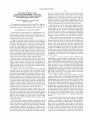
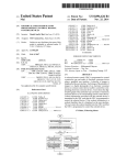
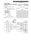
vided. The remote control can be programmed With a code
corresponding to a particular manufacturer and model of the
(51)
1999'
Int. Cl.7 .............................................. .. G08C 19/12
remote controlled device to be controlled. The remote con
trol can also display this code on the remote controlled
(52)
US, Cl, ________________ __ 341/176; 348/162; 340/825_69;
340/825_72; 341/173
device using preexisting circuitry in the remote control. If
the user does not knoW the particular manufacturer/model
(58)
Field Of Search ............................... .. 341/173, 176;
Code Corresponding to the remote Controlled device to be
A programmable, umversal remote control for controllmg
many different of remote controlled devices, such as
May 16! 2000
_
_
televisions, videocassette recorders, and cable boxes is pro
340/82572,8255182569’82537; 348/162,
controlled, he may sequence through the available
163, 164
manufacturer/model codes in the remote control until an
appropriate code is found. Methods are also provided for
(56)
References Cited
programming, displaying, and searching for the appropriate
manufacturer/model code in the remote control.
U.S. PATENT DOCUMENTS
4,626,848 A
12/1986 Ehlers ................. .. 340/82569
8 Claims, 6 Drawing Sheets
U.S. Patent
Feb. 5,2002
Sheet 1 0f 6
US 6,344,817 B1
wxavmk
0%d2o»:
3%QR Mag}
39K
U.S. Patent
Feb. 5,2002
Yakn
IQXWEA imwok
4.5b“was
Sheet 3 0f 6
SiESE
\
\
\
Om
vmlU
E:5
US 6,344,817 B1
US 6,344,817 B1
1
2
METHOD OF DISPLAYING
ted by the standard remote control Was received by the
universal remote control, associated With the button
depressed on the universal remote control, and stored for
subsequent use by the universal remote control. Thus, the
universal remote control learned the appropriate signal to
transmit in response to depressing a particular button. In this
MANUFACTURER/MODEL CODE AND
PROGRAMMABLE UNIVERSAL REMOTE
CONTROL EMPLOYING SAME
CROSS-REFERENCE TO RELATED
APPLICATION
manner, each of the buttons on the standard remote control
could be implemented by the universal remote control.
This application is based on Provisional Patent Applica
tion Serial No. 60/134,555 ?led on May 17, 1999, the
disclosure of Which is incorporated herein by reference.
Universal remote controls often allocate different sections
of the keypad for use in controlling different devices.
Alternatively, a device selection button may be provided,
Which enables the user to selectively control multiple types
BACKGROUND OF THE INVENTION
of electronic devices, such as a televisions, videocassette
This invention relates generally to a programmable, uni
versal remote control, and more particularly to a 15
programmable, universal remote control in Which manufac
turer and model numbers of electronic devices to be con
trolled are stored in the remote control.
recorders, and stereo receivers. The learning mode described
above is used to program the appropriate commands
required to control each of the desired electronic devices.
While universal remote controls have been satisfactory,
they suffer from many shortcomings. For instance, they
Originally, standard remote controls Were provided for
use With a speci?c electronic apparatus to be controlled.
require that the user teach the universal remote control each
of the codes necessary to control each of the electronic
Typically the standard remote control uses infrared signals
to control the operation of electronic devices such as
require several codes, and the user may oWn many electronic
televisions, audio equipment, videocassette recorders, and
devices, programming the universal remote control becomes
devices. Since any particular electronic apparatus may
the like. The appropriate infrared signal is associated With a
a burden. In addition, these codes are typically stored in
particular button or sequence of buttons on a keypad of the 25 random access memory (RAM), Which requires that poWer
remote control. By depressing the button or buttons on the
be maintained to retain its contents. Thus, When the batteries
remote control, the user causes the remote control to trans
are changed, or their poWer has been consumed, the contents
mit the corresponding infrared signal. The electronic device
of RAM are lost, and the user must reprogram the universal
receives the infrared signal, processes its content, and per
remote control.
forms a function associated With the infrared signal.
In order to solve some of these de?ciencies,
HoWever, remote controls of this type have many draW
backs. First, since each electronic device requires its oWn
remote control, the user must keep track of a multitude of
programmable, universal remote controls have been devel
oped With electrically erasable, programmable, read-only
memory (EEPROM), Which maintains its contents Without
poWer. Thus, When the codes are learned by the universal
remote control, they are maintained in EEPROM inde?
nitely. HoWever, in order to retain all of the programming
codes required to control a multitude of electronic devices,
it becomes necessary to provide a relatively large amount of
remote controls, Which can become very cumbersome. In
35
addition, the user must recall Which remote control operates
Which electronic device or be forced to try multiple remote
controls until the correct one is found.
In addition, as the user replaces old electronic apparatus
EEPROM. Since EEPROM is expensive and relatively sloW,
With neWer, more up to-date models, the remote control
this greatly increases the cost of the remote control and
provided With the old equipment can no longer be used to
likely decreases its speed of operation.
control the neW equipment. For instance, if the user oWns a
particular television With having a dedicated remote control,
As a further improvement programmable, universal
upon the purchase of a neW television, the old remote control
Would be useless since it Would likely not be able to control
the neW television. Further, the neW television Would require
yet another remote control, Which Would not reduce the total
remote controls noW use a manufacturer/model code, Which
45
number of remote controls required by the user. Therefore,
a single, universal remote control that can control many
different devices and that can be programmed to control
additional and/or neW electronic devices is desirable.
Programmable, universal remote controls have been
developed that solve these de?ciencies. These remote con
trols may be programmed With codes associated With a
particular manufacturer and model number of the electronic
apparatus to be controlled. In addition, each of the different
programmable, read-only memory (PROM). The user then
55
codes is stored Within the same remote control, Which
enables the user to control multiple electronic devices With
one remote control.
Universal remote controls originally required the user to
“teach”, or the remote control to “learn”, the proper codes to
transmit in response to depressing a particular button on the
remote control. A learning mode Was initiated by selecting
a predetermined sequence of buttons. A button on the
universal remote control Was then depressed, and a button on 65
the standard remote control originally provided to control
the electronic apparatus Was depressed. The signal transmit
provides an index to one of a plurality of complete sets of
programming codes necessary to control a particular manu
facturer and model number of remote controlled device. The
user ?nds the speci?c manufacturer and model number of
his device in a cross-reference table stored in inexpensive,
programs this manufacturer/model code into the universal
remote control, Which Will thereafter transmit the correct set
of programming codes required to control his electronic
device. In this Way, programming codes for a Wide variety
of manufacturers and model numbers can be stored Within
the universal remote control in a relatively inexpensive
manner.
For example, the universal remote control could contain
a ?rst set of program codes for operating a particular
television, a second set of program codes for operating a
particular videocassette recorder (VCR), a third set of pro
gram codes for operating a second type of television, a
fourth set of program codes for operating a second type of
VCR, and so forth. Thus, for the user to invoke a certain set
of codes to control a particular device, the user only needs
to teach the universal remote control the manufacturer/
model code corresponding to the electronic device the user
US 6,344,817 B1
3
4
Wishes to control, and not the complete set of program codes
required to control the electronic device.
The processing circuit generates a program code represen
tative of the device code, and the transmitter transmits the
There are a number of situations in Which the user is
program code to the remote controlled device. The remote
controlled device is in a ?rst state, such as a particular
channel on a television, in response to receiving the program
code, and the ?rst state is indicative of the device code to a
required to determine the manufacturer/model code that has
been programmed into the remote control. Since the major
ity of universal remote controls do not have a display, some
have overcome this problem by using a blinking, light
user.
emitting diode (LED). For multi-digit manufacturer/model
10
As a result of the present invention, a programmable,
universal remote control, is provided, Which is able to
control many different electronic devices, such as
televisions, VCRs, stereo systems, cable boXes, and the like.
In addition, the programmable, universal remote control
15
de?ne a particular electronic device to be controlled, into the
remote control. Further, the programmable, universal remote
codes, the LEI) blinks a speci?c number of times corre
sponding to the ?rst digit, then pauses, and blinks a speci?c
number of times corresponding to the second number, then
pauses, and so forth. Such a display mechanism can be
burdensome for the user Who must count the number of
alloWs a user to program manufacturer/model codes, Which
blinks and record the count for each digit.
SUMMARY OF THE INVENTION
control enables the user to display a current manufacturer/
In accordance With the present invention, a method of
programming a remote control is provided Which includes
the steps of initialiZing a remote controlled device in a ?rst
state (such as on) and initiating a program mode in the
remote control. A ?rst program code is transmitted by the
remote control, and the program mode is terminated if the
model code, Which is already programmed into the remote
control, on a remote controlled device. Yet further, the
programmable, universal remote control can ?nd the correct
manufacturer/model code corresponding to a particular
remote controlled device, and program that manufacturer/
model code into the remote control.
These and other objects, features and advantages of the
remote controlled device changes to a second state, such as
off, in response to receiving the ?rst program code.
Thereafter, a ?rst set of program codes is accessed using a
?rst device code. HoWever, if the remote controlled device
remains in the ?rst state in response to receiving the ?rst
program code, a second program code is transmitted, and so
25
present invention, Will become apparent from the folloWing
detailed description of illustrative embodiments thereof,
Which is to be read in connection With the accompanying
draWings.
BRIEF DESCRIPTION OF THE DRAWINGS
on, until the appropriate program code is found.
The ?rst device code indicates the type of remote con
trolled device if the remote controlled device is in the second
state in response to receiving the ?rst program code.
In further accordance With the present invention a method
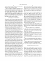
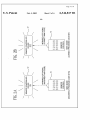
FIGS. 1A and 1B are pictorial representations of a
programmable, universal remote control formed in accor
dance With the present invention in a program mode and a
of displaying a device code on a remote controlled device is 35
FIGS. 2A and 2B are pictorial representations of a
programmable, universal remote control in a seek mode
during Which incorrect programmed code sets and a correct
program code set, respectfully, are selected in accordance
display mode, respectively.
provided, Which includes the steps of initiating a display
mode in a remote control, retrieving a device code stored in
the remote control, transmitting a program code, and chang
ing the remote controlled device to a ?rst state in response
With the present invention.
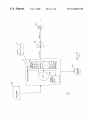
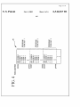
FIG. 3 is a block diagram of a programmable, universal
remote control formed in accordance With the present inven
tion.
to recciving the program code. The device code indicates the
type of remote controlled device, and the program code is
representative of the device code. The ?rst state is repre
sentative of the device code, such as a particular channel on
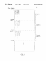
FIG. 4 is a pictorial representation of the contents of a
a television, and indicates the device code to a user.
In still further accordance With the present invention a
remote control having a program mode is provided, Which
includes a processing circuit, a transmitter, and a memory
device. The transmitter transmits the ?rst program code in
response to the remote control being in the program mode,
and the program mode terminates if the remote controlled
device changes to the second state in response to receiving
the ?rst program code. The transmitter transmits the second
program code if the remote controlled device remains in the
?rst state in response to receiving the ?rst program code, and
read-only memory (ROM) of a programmable, universal
45
remote control formed in accordance With the present inven
tion.
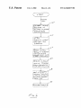
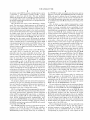
FIG. 5 is a How chart of a program mode and a seek mode
in accordance With a method of the present invention.
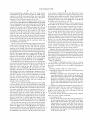
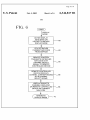
FIG. 6 is a How chart of a display mode in accordance
With a method of the present invention.
DETAILED DESCRIPTION OF THE
PREFERRED EMBODIMENTS
so on until the correct program code is found. The ?rst 55
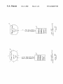
FIG. 1A shoWs a programmable, universal remote control
device code is used to access the ?rst set of program codes
10 formed in accordance With the present invention. The
if the remote controlled device is in the second state in
remote control 10 is initially programmed With a device
response to receiving the ?rst program code. The ?rst device
code indicates the type of remote controlled device if the
remote controlled device changes to the second state in
response to receiving the ?rst program code.
In yet further accordance With the present invention a
remote control having a display mode is provided, Which
includes a processing circuit, a memory device, and a
transmitter. A device code is stored in the memory device,
and the processing circuit retrieves the device code in
response to the remote control being in the display mode.
code, Which identi?es the particular remote controlled
device such as a manufacturer/model code, While in a
program mode. Preferably, the user is provided With a
cross-reference table listing a Wide variety of manufacturers
or brands and model numbers of remote controlled devices
along With the corresponding manufacturer/model code in a
65
user’s manual.
The user Will ?rst look up the speci?c manufacturer and
model number of his remote controlled device and then
program the corresponding manufacturer/model code into
US 6,344,817 B1
5
6
the remote control 10. The remote controlled device can be
a television, a videocassette recorder (VCR), a stereo
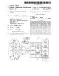
the CPU 30, but Which is retained even after poWer, such as
batteries, is removed. The EEPROM preferably contains the
system, a cable boX, and the like. The user preferably
initiates the program mode by entering a program sequence
M/M code used to indicate the set of program codes that
must be used to control a speci?c remote controlled device.
on a keypad of the remote control 10. The user then enters
The RAM 32 preferably stores data and variables that may
be modi?ed by the CPU 30, but Which are lost When poWer
is removed.
the desired manufacturer/model code to be programmed into
the remote control 10.
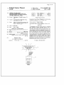
FIG. 1B shoWs the remote control 10 during a display
mode. The user enters a display sequence on the keypad of
the remote control 10, Which initiates the display mode and
10
causes the remote control 10 to transmit a program code or
infrared (IR) channel select signal to the remote controlled
device 12. The IR channel select signal transmitted during
the display mode from the remote control 10 causes the
remote controlled device to change to a channel correspond
15
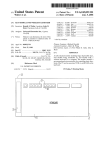
FIG. 4 shoWs a more detailed representation of the
contents of the ROM 26. Each manufacturer and model
number of remote controlled device controllable by the
remote control 10 is represented by a different M/M code.
Each M/M code corresponds to a different program code set
stored in the ROM 26. Each program code set contains
various program codes required to control the remote con
trolled device corresponding to the particular M/M code
ing to the manufacturer/model (M/M) code that Was pro
grammed into the remote control 10 during the program
mode. The user then interprets the channel displayed on the
remote controlled device as representing the current M/M
code programmed into the remote control 10. In this Way, the
associated With the program code set. The program codes
include codes, such as an off-code, an on-code, a one-code,
a tWo-code, a three-code, and so forth, corresponding to
different buttons on the remote control. The program code
sets are preferably stored sequentially Within blocks corre
remote control 10 uses pre-eXisting digital, analog and
infrared circuitry to display the M/M code programmed into
sponding to a particular M/M code, as shoWn in FIG. 4.
Referring again to FIG. 3, the user selects a particular
the remote control 10.
25 channel on the keypad 14 during normal operation, and the
FIGS. 2A and 2B shoW the remote control 10 during a
CPU 30 uses the contents of the M/M code register in
seek mode. Prior to entering the seek mode, the user
EEPROM 24 to access the correct program code set in ROM
preferably turns the remote controlled device 12 on. The
26 corresponding to the current M/M code. The CPU 30 then
user then enters a seek-start sequence on the keypad of the
retrieves the program code associated With the channel
remote control 10, Which causes the remote control 10 to
selected from the appropriate program code set. The pro
enter the seek mode and sequentially transmit program
codes corresponding to the off-command or off-signals
corresponding to each of the MM codes contained in the
remote control 10. FIG. 2A shoWs that the remote controlled
device 12 does not respond to infrared off-signals that do not
correspond to the correct M/M code for that particular
gram code is then output to the ampli?er 18, Which prefer
ably includes transistors, resistors, and other electronic
35
remote controlled device 12, and therefore the remote con
trolled device 12 Will stay on. FIG. 2B shoWs that the remote
controlled device 12 does respond to the infrared off-signal
corresponding to the correct M/M code by turning off. The
displays the selected channel.
The user initiates the program mode by entering the
user enters a seek-stop sequence on the keypad to terminate
the seek mode and store the current M/M code found to be
appropriate for controlling the remote controlled device 12
components Well knoWn in the art. The ampli?er 18 trans
lates the digital output of the microcontroller 16 such that its
electrical characteristics are compatible With the IR LED 20.
The IR LED 20 then transmits the IR channel select signal,
Which represents the channel selected, in response to receiv
ing the output of the ampli?er 18. The remote controlled
device 12 then receives the IR channel select signal and
program sequence on the keypad 14. If the user knoWs
45
in the remote control 10
Which M/M code is appropriate for his particular remote
controlled device 12, the user enters that M/M code on the
The program, display, seek-start and seek-stop sequences
keypad 14. The microcontroller 16 then stores the entered
M/M code into the EEPROM 24 if it is valid.
entered by the user are preferably abnormal sequences of
keys not typically encountered during normal operation of
The user initiates the display mode by entering the display
the remote control, dedicated keys, or any other action
performed by the user to initiate these modes.
FIG. 3 is a block diagram of the programmable, universal
remote control 10, Which includes the keypad 14; a process
sequence on the keypad 14. The microcontroller 16 then
retrieves the current M/M code from the EEPROM 24, and
ing circuit, microprocessor, application speci?c integrated
uses it to access the program code set in ROM 26 corre
55
circuit (ASIC), programmable logic device, or microcon
troller 16; an ampli?er 18; an infrared (IR) light emitting
diode (LED); electrically-erasable, programmable, read
only memory (EEPROM) 24; and an indicator LED 22. The
microcontroller 16 preferably includes read-only memory
(ROM) 26, random-access memory (RAM) 28, and a central
12 then displays the channel selected, Which represents the
current value of the MM code.
Prior to initiating the seek mode, the user preferably turns
processing unit (CPU) 30.
The CPU 30 preferably eXecutes an operational program
residing in the ROM 26. The ROM 26 also contains a
program code set corresponding to each M/M code. The
EEPROM 24 provides storage Which may be modi?ed by
sponding to the current M/M code. The CPU 30 determines
the appropriate program code that represents the current
M/M code and provides that program code to the ampli?er
18. The output of the ampli?er 18 is provided as the contents
of the IR channel select signal via the IR LED 20 to the
remote controlled device 12. The remote controlled device
the remote controlled device 12 on and then enters a
65
seek-start sequence on the keypad 14. The CPU 30 then
preferably loads the EEPROM 24 With the M/M code
corresponding to program code set 1 and outputs the off
US 6,344,817 B1
7
8
code corresponding to program code set 1. If the remote
controlled device 12 is turned off, then the M/M code is
retained in the M/M code register 24 as the correct M/M
code for the particular remote controlled device 12 folloW
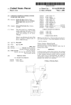
to the remote controlled device in step 64, and the remote
ing entry of the seek-stop sequence by the user.
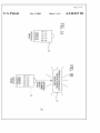
resenting the current value of the MM code in step 68, and
the display mode terminates in step 70.
controlled device displays the channel corresponding to the
IR channel select signal in step 66. The user interprets the
channel displayed on the remote controlled device as rep
HoWever, if the remote controlled device 12 Was not
turned off, the CPU 30 loads the EEPROM 24 With the MM
code corresponding to the neXt program code set folloWing
a delay required for the remote controlled device 12 to
respond. The remote control 10 then transmits the off-code
for the neXt program code set, and the process repeats until
the remote controlled device 12 is turned off. The remote
controlled device 12 is preferably turned on prior to initi
ating the seek mode since such devices typically turn off
faster than they turn on. This decreases the delay required
betWeen off-code transmissions. This delay must account for
the time required by the user to enter the seek-stop sequence
in response to determining that the electronic device has
From the foregoing description, it Will be appreciated by
10
programmable, universal remote control, Which is able to
control many different electronic devices, While enabling the
user to program manufacturer/model codes into the remote
15
control. It Will also be appreciated that the method and
apparatus formed in accordance With the present invention
enables the display of the current manufacturer/model code
programmed into the remote control on a remote controlled
device. It is to be still further appreciated that the method
and apparatus formed in accordance With the present inven
tion provides a universal remote control, Which can ?nd the
correct manufacturer/model code corresponding to a par
ticular remote controlled device, and program that
manufacturer/model code into the remote control.
successfully been turned off.
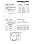
FIG. 5 is a How chart shoWing the sequence of steps in the
program mode and the seek mode. If the MM code is knoWn
by the user in step 32, the user Will enter the program
sequence on the keypad, Which initiates the program mode
in step 34. The user Will then enter the desired M/M code to
be programmed into the remote control on the keypad in step
36, and if the entered sequence is valid in step 38, the CPU
Will store that M/M code in the EEPROM in step 40. The
program mode terminates in step 42. If the entered M/M
code is not valid, then the program mode Will terminate
Without storing the entered M/M code in the EEPROM.
If the M/M code is not knoWn by the user in step 32, then
those skilled in the art that a method and apparatus formed
in accordance With the present invention can provide a
25
Although illustrative embodiments of the present inven
tion have been described herein With reference to the accom
panying draWings, it is to be understood that the invention
is not limited to those precise embodiments, and that various
other changes and modi?cations may be effected therein by
one skilled in the art Without departing from the scope or
spirit of the invention.
What is claimed is:
1. A method of displaying a device code on a remote
the user turns the remote controlled device on in step 44, and 35
controlled device, the device code being representative of
enters the seek-start sequence on the keypad in order to
the remote controlled device, the method comprising the
initiate the seek mode in step 46. The CPU Will then
preferably load the EEPROM With the M/M code corre
sponding to program set 1 in step 48, and the remote control
Will transmit an off-code corresponding to program code set
1 in step 50. If the remote controlled device is turned off in
step 52 in response to the off-code transmitted in step 50,
then the seek-stop sequence is entered by the user to
terminate the seek mode, and the contents of the EEPROM
represents the correct the MM code that controls that
speci?c remote controlled device.
steps of:
initiating a display mode in a remote control;
retrieving the device code, the device code being stored in
the remote control;
transmitting a program code, the program code being
transmitted from the remote control, the program code
being representative of the device code; and changing
45
the remote controlled device to a ?rst state Which is
displayed in response to receiving the program code,
the ?rst state being representative of the device code,
the ?rst state being indicative of the device code to a
HoWever, if the remote controlled device Was not turned
user.
off in step 52, the CPU Will load the EEPROM With the MM
code corresponding to the neXt program code set folloWing
the delay in step 54. The delay is included to alloW time for
manufacturer/model code on a remote controlled device as
the remote controlled device to respond and the user to
notice its response prior to transmission of the neXt off-code.
program mode includes the step of selecting at least one
FolloWing the delay, the remote control transmits the off
2. Amethod of displaying information representative of a
de?ned by claim 1, Wherein the step of initiating the
55
code corresponding to the neXt program code set in step 56.
This process repeats With step 52 until the remote controlled
device is turned off, at Which point the contents of the
3. A remote control, the remote control having a display
mode, the remote control comprising:
a processing circuit;
a memory device, the memory device being responsive to
the processing circuit, the memory device having a
device code stored therein, the device code being
EEPROM correctly indicates the MM code corresponding
to the particular remote controlled device to be controlled.
FIG. 6 shoWs the sequence of steps involved in the display
representative of a remote controlled device, the pro
mode. The user enters a display sequence on the keypad to
cessing circuit retrieving the device code from the
initiate the display mode in step 60, and the CPU retrieves
the current M/M code from the EEPROM in step 62. The
remote control then transmits the M/M code retrieved from
the EEPROM as the contents of the IR channel select signal
button on the remote control.
memory device in response to the remote control being
65
in the display mode, the processing circuit generating a
program code, the program code being representative
of the device code; and
US 6,344,817 B1
10
a transmitter, the transmitter being responsive to the
processing circuit, the transmitter transmitting the pro
gram code to the remote controlled device, the remote
controlled device being in a ?rst state Which is dis
played in response to receiving the program code, the
?rst state being representative of the device code, the
?rst state being indicative of the device code to a user.
4. A remote control as de?ned by claim 3, Wherein the
processing circuit includes at least one of a microcontroller,
microprocessor, application speci?c integrated circuit
(ASIC), and programmable logic device.
5. A remote control as de?ned by claim 3, Wherein the
remote controlled device is a television, the television being
able to be tuned to at least one of a plurality of channels, the
5
?rst state being representative of at least one of the plurality
of channels to Which the television is tuned.
6. A remote control as de?ned by claim 3, further includ
ing at least one button, Wherein the display mode is initiated
by selecting the at least one button.
7. A remote control as de?ned by claim 3, further includ
ing at least one button, Wherein the program mode is
terminated by selecting the at least once button.
8. A remote control as de?ned by claim 3, Wherein the
transmitter includes an infrared (IR), light-emitting diode
(LED).
UNITED STATES PATENT AND TRADEMARK OFFICE
CERTIFICATE OF CORRECTION
PATENT NO.
DATED
Page 1 of 8
: 6,344,817 B1
: February 5, 2002
INVENTOR(S) : Christopher J. VerZulli
It is certified that error appears in the above-identi?ed patent and that said Letters Patent is
hereby corrected as shown below:
Title page,
The title page showing the illustrative figure should be deleted to be replaced
with the attached title page.
Drawings,
Sheets 1-6, consisting of Figs 1-6, should be deleted and substitute therefore
the corrected sheets 1-6, as shown on the attached pages.
Column 3
Line 9, now reads "codes, the LEI" should read -- codes, the LED --;
Line 39, now reads "to receiving the program code." should read -- to receiving
the program code. -
Signed and Sealed this
Seventeenth Day of September, 2002
Attest:
JAMES E. ROGAN
Attestin g O?’icer
Director ofthe United States Patent and Trademark O?‘i'ce
Page 2 of 8
(12) United States Patent
(10) Patent No.:
Verzulli
(54)
US 6,344,817 B1
(45) Date of Patent:
METHOD OF DISPLAYING
4.703.359 A
MANUFACfURER/MODEL CODE AND
PROGRAM“ UNI‘ERSAL REMOTE
NTR
mu,
@DIE
Co
0L
LOYING 5
4,774,511
4.866.434
5.515.052
5.614.906
(75) Inventor: Christopher .1. Verntlli. Setauket. NY
Feb. 5, 2002
10/1987 Rumbolt e! :11. .......... .. 343/734
A
A
A
A
9/1988
9/1989
5/1996
3/1997
Rumbolt et al.
Keenan
Darbee
Hayes or 11.
340/32569
340/82572
341/176
341/176
OTHER PUBLICATIONS
(US)
v
p
_
_
International Search Report-Prepared
for Correspondinz
(1'3)
Assignee: US. Electronics Components Corp..
Pun 1656mm‘ NY (Us)
_\
\I
5 H344
International. pplication . o. PCT/U O0 .1 _.
( *)
Notice:
Primary Eruminer-Michael Horabik
Assistant Etamt'ner—Albert K. Wong
Subject to any disclaimer. the term of this
patent is extended or adjusted under 35
U.S.C. 154(b) by 0 days.
‘
(74-l Attorney. Agent. or Firm-Hotfmzmn & Baron. LLP
1571
'
ABSTRACT
(21)
Appl. No.: 09/572,687
4
[22)
Filed:
(60)
Relmed U-s- Apphcanon Data
Provisional application No. 60/134555. ?led on May 17.
vided. The remote control can be programmed with a code
Corresponding to a particular manufacturer and model of the
(51)
[999‘
Int. Cl.7
............................... .. G08C 19/12
remote controlled device to be controlled. The remote con
trol can also display this code on the remote controlled
{52) US. CL
341/176; 348/162; 340/3559;
device using preexisting circuitry in the remote control. 1f
340/3573; 341/173
the user does not know the particular manufacturer/model
Field of Search ............................... .. 341/173. 176;
Code corresponding to the remote Controlled device [0 be
May 16, 2000
many dilferent of remote controlled devices. such as
l
(58)
_
A programmable. universal remote control for controlling
_
televisions. videocassette recorders. and cable boxes is pro
340182571 32557‘ 32559 33537; 348/162_
controlled, he may sequence through the available
163’ 164
manufacturer/model codes in the remote control until an
(56)
appropriate code is found. Methods are also provided for
programming, displaying, and searching for the appropriate
References Cited
manufacturer/model code in the remote control.
US. PATENT DOCUMENTS
4.626.848 A
12/1986 Ehlers
340/8216‘)
8 Claims, 6 Drawing Sheets
REMOTE CONTROLLED
DEVICE CHANNEL
SELECTED
, INFRARED
ICHANNEL
I SELECT
' SIGNAL
REMOTE
CONTROL
DISPLAY
MODE
Page 3 0f 8
U.S. Patent
Feb. 5,2002
Sheet 1 0f 6
6,344,817 B1
En.by
£0 m
T2063
En.:W
mroq ouzam><_Iomr omzHFqu //7\
/
Page 7 0f 8
US. Patent
Feb. 5, 2002
6,344,817 B1
Sheet 5 0f 6
5/6
FIG. 5
PROGRAM
MODE
ENTER PROGRAM
SEQUENCE ON
KEYPAD TO INITIATE
PROGRAM MODE
IS
M/M CODE
KNOWN BY
USER
7
SEEK MODE
TURN REMOTE
CONTROLLED
DEVICE ON
34
I
I
ENTER SELF-START
ENTER DESIRED
M/M CODE ON
KEYPAD
KEYPAD TO INITIATE
SEEK MODE
SEQUENCE ON
I
CPU LOADS EEPROM
WITH M/M CODE
CORRESPONDING
TO PROGRAM SET 1
IS
ENTERED
M/M CODE
VALID
I
'7
REMOTE CONTROL
YES
TRANSMITS OFF-CODE N 50
CORRESPONDING TO
PROGRAM CODE SET1
CPU STORES
ENTERED M/M COD E
IN EEPROM
TERMINATE
PROGRAM MODE
54
WAS
REMOTE
CONTROLLED
DEVICE
TURNED
OFF
CPU LOADS EEPROM
WITH M/M CODE
CORRESPONDING TO
NEXT PROGRAM CODE
SET FOLLOWING
A DELAY
I
REMOTE CONTROL
TRANSMITS
OFF-CODE FOR
NEXT PROGRAM
CODE SET
INITIATE SEEK-STOP
SEQUENCE TO
TERMINATE SEEK MODE
(REMOTE CONTROL IS
PROGRAMMED WITH
M/M CODE WHICH
SUCCESSFULLY CONTROLS
REMOTE CONTROLLED
DEVICE)
Page 8 0f 8
US. Patent
Feb. 5, 2002
Sheet 6 0f 6
6,344,817 B1
6/6
FIG. 6
I START I
DISPLAY
‘I MODE
ENTER DISPLAY
SEQUENCE ON
KEYPAD TO INITIATE
DISPLAY MODE
II
CPU RETRIEVES
CURRENT M/M CODE
FROM EEPROM
N62
II
REMOTE CONTROL
TRANSMITS RETRIEVED
M/M CODE AS IR
CHANNEL SELECT
SIGNAL TO REMOTE
CONTROLLED DEVICE
I
REMOTE CONTROLLED
DEVICE DISPLAYS
CHANNEL CORRESPONDING x66
TO IR CHANNEL
SELECT SIGNAL
II
USER INTERPRETS
CHANNEL DISPLAYED
ON REMOTE CONTROLLED x68
DEVICE AS CURRENT
M/M CODE
TERMINATE
DISPLAY MODE