
1
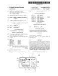
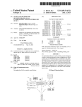
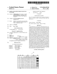
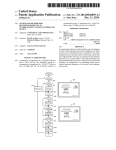
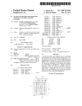
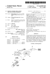
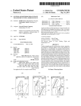
USOO8896426B1
(12) United States Patent
(10) Patent N0.2
Mui
(45) Date of Patent:
(54) GRAPHICAL USER INTERFACE FOR
(75)
(73)
2
Nov. 25, 2014
gar}??? 54 Bit 1
3.0
l
awae
a .
PROGRAMMING UNIVERSAL REMOTE
631573319 A
120000 Johns et al‘
CONTROL DEVICES
6,211,856 B1
6,211,870 B1
4/2001 Choi et a1.
4/2001 Foster
Inventor:
6,225,938 B1
5/2001 Hayes et a1.
6,408,435 B1 *
6/2002
Sato .............................. .. 725/58
6,763,148 B1
7/2004
Stember et a1.
7,653,212 B2*
1/2010 Haughawoutetal. ...... .. 382/100
-
Daniel SauFu Mui, San Jose, CA (US)
.
Asslgnee- UEI Cayman Inc-s Santa Ana, CA (Us)
( * ) Notice:
6,774,813 B2 ,,
8/2004 van Be 531‘ “““““ n 340/825‘69
Subject to any disclaimer, the term of this
532m
patent is extended or adjusted under 35
U.S.C. 154(b) by 1371 days.
(21)
US 8,896,426 B1
2001/0017615 A1
APPL NO; 11,704,669
(22) Filed:
8/2001 Lin et a1.
2001/0045819 A1
11/2001 Harris et al.
2002/0143805 A1
10/2002 Hayes et a1.
(Continued)
Feb. 9, 2007
FOREIGN PATENT DOCUMENTS
(51)
Int. Cl.
(52)
G05B 11/01
US. Cl.
(200601)
EP
WO
W0
1578016 A1
2005/043484
9/2005
5/2005
WO 2006125357 A1 * 11/2006
.............. .. G06F1/26
USPC .............. .. 340/12.23; 340/12.22; 340/426.14;
340/539.19; 340/1051; 348/734; 341/176
(58)
Field of Classi?cation Search
CPC ......... .. G08C 2201/20; G08C 2201/21; G08C
2201/30; G08C 2201/92; H04N21/42225;
H04N 21/42226
USPC ................ .. 340/825, 539.19, 426.14, 426.35,
Primary Examiner * Mohammad Ghayour
ASS/Wm Examiner * Nay T1111
(74) Allvrney. Age/11. or Firm * Greenberg Trawig, LLP
(57)
ABSTRACT
A universal remote control (URC) is programmed to control
340/10.51, 7.39, 5.2, 5.214525,
a particular type and make of electronic consumer device
340/12.22*12.23; 348/734; 341/176;
using a graphical user interface. A plurality of images is
725/46, 47
See application ?le for complete search history.
displayed on the user interface. Each image of the plurality of
images is a digital photograph of an electronic consumer
device or a remote control device usable to control the corre
(56)
References Cited
sponding electronic consumer device. A user selects the digi
tal photograph of the particular type and make of electronic
U.S. PATENT DOCUMENTS
4,623,887 A
11/1986 Welles, 11
4,774,511
4,959,810
5,263,098
5,481,256
5,515,052
9/1988
9/1990
11/1993
1/1996
5/1996
A
A
A
A
A
Rumbolt et a1.
Darbee et a1.
Horikami
Darbee et a1.
Darbee
5,929,849 A *
7/1999
5,959,751 A
9/1999 Darbee et a1.
6,008,735 A *
12/1999
consumer device or its corresponding remote control device.
Kikinis ....................... .. 725/113
Codeset information associated With the selected device is
transmitted to the URC such that the URC is pro grammed to
control the selected device. If the codeset information is a
codeset identi?er, then it is displayed on the user interface.
The user enters the codeset identi?er into the URC such that
the URC is programmed to control the selected device.
17 Claims, 5 Drawing Sheets
Chiloyan et a1. ....... .. 340/825.22
START
DISPLAYING A SELECTION MENU THAT ALLOWS A USER TO
SELEcT A TYPE AND BRAND FROM A LIST OF ELECTRONIC
DEVICES
DISPLAYING A SELECTION MEN THAT ALLOWS A usERTcI
SELEC'T AN IMAGE FROM A LIST
MAEES CORRESPONDING
TO THE SELECTED TYPE AND BRAND OF ELECTRONIC DEVICES
54
SENDING CODESEI' INFORMA‘nON OF
DISPLAYING A CODESET IDENTIFIER
THE SELECTED IMAGE TO THE
CORRESPONDING TO THE SELECTED
UNIVERSAL REMOTE CONTROL DEVICE
551
RECENING THE CODESET INFORMATION
SUCH THAT THE UNIVERSAL REMOTE
CONTROL DEVICE IS PROGRAMMED TO
CONTROL AN ELECTRONIC DEVICE
CORRESPONDING TO THE SELECTED
I
55A
PROGRAMMING THE UNIVERSAL REMOTE
CONTROL DEVICE TO USE THE CODESET
IDENTIFIER To CONTROL AN ELECTRONIC
DEVICE OORRESPONDING TO THE
SELECTED IMAGE
US 8,896,426 B1
Page 2
(56)
References Cited
U.S. PATENT DOCUMENTS
2003/0025840
2003/0095156
2003/0103088
2003/0141987
2003/0189509
2004/0003001
A1
A1
A1
A1
A1
A1
2/2003
5/2003
6/2003
7/2003
10/2003
1/2004
Arling
Klein et a1.
Dresti et al.
Hayes
Hayes et al.
Shimura
2004/0070491
2004/0257259
2005/0054289
2006/0050142
2006/0227997
2007/0080845
2007/0096283
2007/0100670
2007/0217650
A1
4/2004 Huang et al.
A1
12/2004 Jindal
A1
3/2005 Salazar et al.
A1* 3/2006 Scott et al. ............... .. 348/1405
A1
10/2006 Au et al.
A1
4/2007 Amand
A1
5/2007 Ljung et al.
A1* 5/2007 Celona et al. ................... .. 705/4
A1
9/2007 Ota et a1.
* cited by examiner
US. Patent
Nov. 25, 2014
US 8,896,426 B1
Sheet 1 0f 5
“SYEYEM
i
.98.
3
G?ERA?§QNAL
SiG Niki.
§.....
3M N. M
.
m3
/
_/ agmm
/
wwziss
ETWORK
WTE'R?AQE
WAGE»
,,,,,,,,,,,,,,,,,,,,,,,,,,,,,,,, “N”
3
R519.
PEG, ’3
.
if
US. Patent
NOV. 25, 2014
I
US 8,896,426 B1
Sheet 2 0f 5
START
V
DISPLAYING A SELECTION MENU THAT ALLOWS A USER TO
SELECTA TYPE AND BRAND FROM A LIST OF ELECTRONIC
DEVICES
51
w
V
DISPLAYING A SELECTION MENU THAT ALLOWS A USER-TO
SELECT AN IMAGE FROM A LIST OF IMAGES CORRESPONDING w 52
TO THE SELECTED TYPE AND BRAND OF ELECTRONIC DEVICES
NO
CONFIRM?
/ 54
v
v
SENDING CODESET INFORMATION OF
THE SELECTED IMAGE TO THE
UNIVERSAL REMOTE CONTROL DEVICE
DISPLAYING A CODESET IDENTIFIER
CORRESPONDING TO THE SELECTED
IMAGE
/ 55
v
V
RECEIVING THE CODESET INFORMATION
SUCH THAT THE UNIVERSAL REMOTE
CONTROL DEVICE IS PROGRAMMED T0
CONTROL AN ELECTRONIC DEVICE
CORRESPONDING TO THE SELECTED
IMAGE
[54A
[55A
PROGRAMMING THE UNIVERSAL REMOTE
CONTROL DEVICE TO USE THE CODESET
IDENTIFIER TO CONTROL AN ELECTRONIC
END
FIG. 2
DEVICE CORRESPONDING TO THE
SELECTED IMAGE
US. Patent
Nov. 25, 2014
Sheet 5 0f5
US 8,896,426 B1
$02.,
.. 3‘23.
..
"
2m WEE
UEEER
w m;
22mm;
:mmgs
i143
»
~42
MN
SE? mp 524,»;
PRQCEW~§R
l
§ 1? -
s
,, , ‘;g
Hm W?
'
I
a
Q
KEY
uwvaasm,
mmmm,
mg
................................................ .,
k-iizii??CONTleER
~~-
‘
mmmv
i CGGESET am
233 Mi RCA
RCA
a,
g
US 8,896,426 B1
1
2
GRAPHICAL USER INTERFACE FOR
PROGRAMMING UNIVERSAL REMOTE
CONTROL DEVICES
of electronic consumer device to be controlled (or its corre
sponding remote control device that is to be programmed).
Codeset information associated with the selected device is
outputted to the URC such that the URC is programmed to
control the selected device.
An exemplary device comprises a memory, and a processor
TECHNICAL FIELD
for executing an image-selection routine that displays a plu
The disclosed embodiments relate to methods for pro gram
ming a universal remote control device.
rality of images on a display screen and outputs codeset
information in response to a selection of one of the plurality of
BACKGROUND
images. Each image of the plurality of images is a digital
photograph of an electronic consumer device or a remote
A universal remote control (URC) device transmits opera
control device usable to control the electronic consumer
device. In one example, the digital photographs of the plural
ity of images are stored in the memory as compressed digital
image ?les. In another example, the digital photographs are
tional signals to control one or more electronic consumer
devices such as TVs, VCRs; set-top boxes, audio home the
atre systems, and CD/DVD players. A particular brand and
make of electronic consumer device responds to operational
signals containing a particular set of keycodes and performs
the corresponding functions. In order to provide the function
ality of a URC device, various types of keycodes are stored in
codesets as a codeset database format. Each codeset is iden
received from a centralized location such as a central cable
network.
The selected image corresponds to the particular type and
make of electronic consumer device to be controlled by the
20
ti?ed by a three digit codeset identi?er associated with a
particular brand and make of electronic consumer device. A
URC device generally stores hundreds of codesets in a
codeset database and is programmed to use one particular
codeset to control one particular electronic consumer device.
Typically, a user is provided with a manual which includes
a list of codeset identi?ers corresponding to various elec
25
tronic consumer devices. The user uses the manual to deter
mine the correct codeset identi?er corresponding to each
electronic consumer device to be controlled, and then manu
URC. Codeset information is either a codeset identi?er or a
codeset associated with the selected device. In one embodi
ment, the codeset information is transmitted to the URC
though an audio connection. By providing an audio connector
in the URC, the URC can receive the codeset information
across the audio connection and is automatically pro
grammed to control the selected device. In another embodi
ment, the codeset information is a codeset identi?er and is
displayed on the display screen. The user views the codeset
identi?er (for example, a three-digit code) on the display
30
ally enters that codeset identi?er into the URC device. This
screen, and then manually enters the codeset identi?er into
the URC to program the URC to control the selected device.
process is tedious and time-consuming. Further, if the manual
In one advantageous aspect, besides the codeset informa
of for the URC device is lost, then the user will have no way
tion, device information including device description infor
to program the URC device except by obtaining another
manual (for example, from the manufacturer or by calling
customer service center to get programming instructions). In
addition, the codeset that may be selected for use by the URC
device is limited to the codesets stored in the codeset database
and provided in the manual. The URC device needs a rela
tively large amount of memory to store the entire codeset
database and providing this large amount of memory
35
detailed description below. This summary does not purport to
de?ne the invention. The invention is de?ned by the claims.
40
BRIEF DESCRIPTION OF THE DRAWINGS
The accompanying drawings, where like numerals indicate
increases the cost of the URC device.
Some URC devices have the capability of being pro
like components, illustrate embodiments of the invention.
grammed without requiring the user to enter a codeset iden
ti?er manually. This type of URC device is typically able to
mation and device behavior characteristics information can
also be transmitted to the URC through an audio connection.
Other embodiments and advantages are described in the
FIG. 1 illustrates a system in accordance with one novel
45
aspect.
operate in an “auto search” mode such that the user does the
auto search to ?nd the desired codeset. However, auto search
requires the user to take multiple programming steps to set up
FIG. 2 is a ?owchart of a method for programming a
universal remote control device.
the auto search. Scanning through the entire codeset database
interface that is involved in the method for programming a
universal remote control device.
is also time-consuming. Thus, a market exists for a universal
remote control device that can be easily programmed,
FIG. 3 is an example of a ?rst selection menu of a user
50
FIG. 3A is an example of a second selection menu of a user
interface that is involved in the method for programming a
universal remote control device.
whereby a user will not need to determine a codeset identi?er
from a user manual.
FIG. 4 is another example of a ?rst selection menu of a user
SUMMARY
55
interface.
FIG. 4A is another example of a second selection menu of
A universal remote control (URC) is programmed to con
trol a particular type and make of electronic consumer device
a user interface.
using a graphical user interface. In one embodiment, a user
interface is displayed on a display screen. The user interface 60
aspect.
FIG. 5 illustrates a system in accordance with one novel
includes a plurality of images which are digital photographs
DETAILED DESCRIPTION
of electronic consumer devices or remote control devices that
are used to control the corresponding electronic consumer
devices. The digital photographs are displayed in a prioritized
order based on market popularity of the corresponding elec
tronic consumer devices. A user views the display screen and
selects the digital photograph of the particular type and make
Reference will now be made in detail to some embodi
ments of the invention, examples of which are illustrated in
65
the accompanying drawings.
FIG. 1 is a diagram of a system 1 in accordance with one
novel aspect. System 1 includes a universal remote control
US 8,896,426 B1
3
4
(URC) device 2, a personal computer (PC) 3 and several
DVD device to be controlled by URC 2, then the user con
electronic consumer devices including: a VCR/DVD player
4, a set-top box 5, an audio home-theatre system 6, and a
television 7. URC 2 emits operational signals 8 from an IR
option (step 53 of FIG. 2).
In the example of FIG. 3A, the images displayed in the
?rms the selection of DVD HD841 by selecting the “yes”
transmitter 20 to control electronic consumer devices. URC 2
second selection menu are photographs of the electronic con
includes a microcontroller 21, memory 22, and an RCA jack
24. Memory 22 contains a codeset database 23. (For addi
tional information including examples of a codeset database
sumer devices to be controlled by URC 2. In another example,
the second selection menu displays photographs of the
remote control devices that control the corresponding elec
tronic consumer devices.As illustrated in FIG. 4 and FIG. 4A,
and the content of a codeset and related information on how to
use a codeset to generate an IR operational signal, see: US.
after the user ?rst selects device type VCR and brand name
SAMSUNG from the ?rst selection menu, the second selec
patent application Ser. No. 10/777,023, entitled “Interactive
Web-Based Codeset Selection and Development Tool”, by
Lee et al., ?led Feb. 20, 2004 (the entire subject matter of
which is incorporated herein by reference)). PC 3 is coupled
to a monitor having a display screen 30. PC 3 is also coupled
to a storage medium (for instance, a DVD disc as illustrated)
36. PC 3 is of typical PC construction and includes a CPU 31,
memory 32, a network interface 33, a storage device (for
instance, a DVD driver as illustrated) 34, and a audio OUT
RCA jack 35. PC 3 is connected to a network (for instance, the
tion menu displays photographs of all remote control devices
that are used to control SAMSUNG VCR devices. This
method is especially useful when the device type is TV. Tele
visions have similar appearances among different models. On
the other hand, the appearances of remote control devices that
control different models of televisions are usually different.
Therefore, it may be easier for the user to pick and choose a
20
visions.
internet as illustrated) 38. PC 3 receives digital images 39
from internet 38 through a network connection. PC 3 also
transmits codeset information 43 to URC 2 through an audio
cable 40. Audio cable 40 has two RCA plugs 41 and 42. RCA
There are thousands of electronic consumer devices and
remote control devices available on the market. Each device is
represented by a digital photograph which is stored as a
25
image-selection routine 37 from DVD disc 36. CPU 31 then
executes image-selection routine 37 and displays a user inter
images 39 is quite large. The content of digital images 39 also
30
changes rapidly as manufacturers continue to make new
devices and to phase out obsolete old ones. In one example,
digital images 39 are stored in DVD disc 36 and are then
uploaded by CPU 31 through DVD driver 34 when the second
selection menu is displayed on display screen 30. However, it
35
face 40 on display screen 30. The user then uses either a
mouse or a keyboard or other user input device to interact with
user interface 40 and to make selections.
FIG. 2 is a ?ow chart of a method of programming URC 2
illustrated in FIG. 1. FIG. 3 and FIG. 3A are examples of
screen displays of user interface 40 that are involved in the
method of FIG. 2. In the example of FIG. 3, CPU 31 executes
image-selection routine 37 and displays a ?rst selection menu
of user interface 40 on display screen 30 (step 51 of FIG. 2).
digital image ?le. In the example of FIG. 1, digital images 39
represent the digital image ?les of all electronic consumer
devices and remote control devices. A digital image ?le may,
for example, be a JPEG ?le. As a result, the size of digital
plug 41 is plugged into RCA jack 24 of URC 2, and RCA plug
42 is plugged into RCAjack 35 of PC 3.
FIG. 1 illustrates a method of using PC 3 to program URC
2 to control a particular brand and make of electronic con
sumer device. A user inserts DVD optical disc 36 into DVD
driver 34 of PC 3. DVD disc 36 contains an image-selection
routine 37 that is executable on CPU 31 of PC 3. PC 3 loads
particular brand and make of television by looking at the
photographs of corresponding remote control devices of tele
is more cost effective to maintain and update digital images
39 in a central location such as an internet site. When the user
selects a particular type and brand of electronic consumer
devices from the ?rst selection menu, PC 3 sends a request to
download all digital image ?les of the selected type and brand
40
of electronic consumer devices from the internet site. The
downloaded digital photographs are then displayed on the
second selection menu.
For some popular electronic device types and brands, there
may be many pages of digital photographs to, be displayed.
The ?rst selection menu allows the user to select a device type 45 For instance, there may be dozens of different models of
from a list of device types such as TV, VCR, DVD, and cable
set-top box. The ?rst selection menu also allows the user to
select a brand name from a list of manufacturers such as
Hitachi, Mitsubishi, Panasonic, Philips and more. The user
can select the “next” option to go to next page for more brand
name selections, or select the “prev” option to go back to the
previous page. As illustrated in FIG. 3, if the user wants to
program URC 2 to control a SAMSUNG DVD device, then
the user selects device type DVD and brand name SAM
SUNG.
After the user selects device type DVD and brand name
50
televisions are manufactured by Toshiba. It is therefore time
consuming for the user to browse through all the pages of the
second selection menu and select the right photograph. One
way of improving the second selection menu is to prioritize
each photograph based on market popularity of the corre
sponding device and to display the photograph in the order of
its priority. Market popularity of a device is measured by
number of unit sales, consumer rating, and other factors. The
most popular models of the electronic consumer devices are
55
then displayed ?rst in the front page, thereby reducing the
amount of time generally required by a user to select the
SAMSUNG, a second selection menu of user interface 40 is
proper digital photograph.
displayed on display screen 30 (step 52 of FIG. 2). In the
example of FIG. 3A, the second selection menu displays
photographs of all DVD devices that are manufactured by
HD841, PC 3 sends (step 54 ofFIG. 2) codeset information 43
After the user con?rms the selection of SAMSUNG DVD
60
SAMSUNG. The user uses the user interface to select a pho
example, codeset information 43 is a three-digit codeset iden
ti?er corresponding to SAMSUNG DVD HD841. URC 2
receives (step 55 of FIG. 2) the codeset identi?er from PC 3.
tograph of the SAMSUNG DVD device to be controlled. The
user browses through all the photographs by selecting the
“prev” and “next” options. As illustrated in FIG. 3A, the user
picks model HD841. The photograph of SAMSUNG DVD
model HD841 is then enlarged for further veri?cation. If the
photograph of HD841 looks the same as the SAMSUNG
of the selected electronic consumer device HD841 to URC 2.
Codeset information 43 may be in various forms. In one
65
Microcontroller 21 of URC 2 then programs URC 2 to use a
codeset corresponding to the received three-digital codeset
identi?er. After URC 2 has been programmed to use the
US 8,896,426 B1
5
6
correct codeset stored in codeset database 23, URC 2 is then
user inserts DVD optical disc 111 into DVD player 104. DVD
able to send appropriate operational signals to control SAM
player 104 plays DVD optical disc 111 and displays user
SUNG DVD HD841.
interface 110 on TV 106. The user then uses DVD remote
In another example, codeset information 43 is the actual
codeset of SAMSUNG DVD HD841. Instead of sending the
codeset identi?er, PC 3 sends the actual codeset of SAM
SUNG DVD HD841 to URC 2. In this example, URC 2 does
control device 108 to select a particular, brand and make of
electronic consumer device. In the example of FIG. 5, digital
images 143 represent digital image ?les of all electronic
consumer devices and remote control devices. Digital images
143 are uploaded from DVD optical disc 111 and are dis
not need to store the entire codeset database 23 in memory 22.
Instead, URC 2 receives the codeset from PC 3 and is pro
grammed to use the codeset to control DVD HD841. The
advantage of this method is that it saves memory space and
reduces the cost of URC 2. URC 2 only needs to have enough
played on the second selection menu, as illustrated in FIG. 4.
After the user con?rms the selection of SAMSUNG DVD
HD841, codeset information 153 is then transmitted to URC
102. In the example of FIG. 5, codeset information 153 is
transmitted through an audio cable 150 from DVD player 104
to URC 102. Audio cable 150 has two RCA plugs 151 and
152, which are plugged into RCA jack 133 of URC 102 and
RCA jack 116 of DVD player 104. URC 102 receives codeset
information 153 and is then programmed to control SAM
SUNG DVD HD841 using the correct codeset. Alternatively,
memory to store one or a small number of codesets, as
opposed to an entire database of codesets.
The above illustrated method is convenient because URC 2
is programmed automatically after the user selects the pho
tograph of the electronic consumer device or its correspond
ing remote control device. However, a typical hand held
remote control device is only capable of one-way transmis
sion, i.e., it only emits operational signals to control elec
a codeset identi?er of SAMSUNG HD841 is displayed on TV
20
106, and the user programs URC 102 by entering the codeset
identi?er into URC 102.
tronic consumer devices. In order to receive codeset informa
tion 43 automatically, URC 2 has to be able to do two-way
In the example of using a set-top box 103, the method of
communication. In the example of FIG. 1, RCA jack 24 is
con?guring URC 102 is the same as described above with two
included in URC 2. PC 3 sends out codeset information 43
onto RCA jack 35. URC 2 then receives codeset information
43 from RCA jack 24 through audio cable 30. Aside from an
differences. First, image-selection routine 114 is stored inside
25
audio connection, serial communication or wireless commu
nication may also be used between URC 2 and PC 3. Regard
less of the type of communication, extra cost is required for
URC 2 to receive codeset information 43.
This extra cost in receiving codeset information 43 is elimi
set-top box 103. Processor 112 executes image-selection rou
tine 114 and displays user interface 110 on TV 106 (some
times TV 106 contains a built-in set-top box 103). The user
then uses remote control 107 to make selections. In some
situation, set-top box 103 contains a key interface 117, and
30
nated in the following example. As illustrated in FIG. 2, after
the user used key interface 117 to make selections. Second,
digital images 143 are not uploaded from a DVD disc. If
set-top box 103 is a satellite set-top box, then digital images
the user con?rms the selection of the image of SAMSUNG
143 are received from satellite 140 through satellite dish 141.
DVD HD 841 (step 53), PC 3 displays a three digit codeset
If set-top box 103 is a cable set-top box, then digital images
identi?er of HD 841 on display screen 30 (step 54A of FIG.
35
143 are received from a central cable station 142 through a
2). The User manually programs URC 2 by entering the
displayed codeset identi?er into URC 2 (step 55A of FIG. 2).
cable network. Therefore, this method eliminates the need of
providing local storage of all the digital images or of an extra
URC 2 is then programmed to control SAMSUNG HD 841
DVD disc for the user to con?gure URC 102.
URC 102 is not necessary a hand held remote control
device. In one example, URC 102 is embedded inside set-top
box 103. URC 102 is programmed the same way as illustrated
using the codeset corresponding to the displayed codeset
identi?er. Although the user is still involved in manually
40
pro gramming URC 2, no extra co st is required to transmit the
codeset identi?er to URC 2.
FIG. 5 is a diagram of a system 101 in accordance with one
novel aspect. System 101 includes a universal remote control
above. The only difference is that codeset information 153 is
internally transmitted to URC 102 within set-top box 103.
After URC 102 has been programmed to control a particular
(URC) 102, a set-top box 103, a DVD player 104, an audio
home-theatre system 105, and a TV 106. Set-top box 103
includes a processor 112, memory 113, a RCAjack 115, and
a key interface 117. Memory 113 includes an image-selection
routine 114. Set-top box 103 is either a satellite set-top box or
45
a cable set-top box. A satellite set-top box communicates to a
electronic consumer device, set-top box 103 acts like an IR
blaster to send out operational signals to control that particu
lar electronic consumer device.
In one advantageous aspect, microcontroller 130 of URC
102 includes an on-chip analog-to-digital converter. The ana
50
log-to-digital converter is provided in the integrated circuit
satellite 140 through a satellite dish 141. A cable set-top box
design of microcontroller 130 for use in other high-volume
communicates to a central cable station 142 through a cable
55
microcontroller applications (non-remote control device
applications) of the microcontroller integrated circuit design.
An analog input terminal of the microcontroller integrated
circuit that is coupled to the input of the analog-to-digital
60
other interfacing circuitry between the microcontroller inte
grated circuit and the RCA jack. The analog-to-digital con
verter receives the signal on RCA jack 133, digitizes it, and
the processor within microcontroller 130 analyzes the digi
network. Set-top box 103 is controlled by a set-top remote
control device 107. Remote control device 107 emits opera
tional signals 121 from IR transmitter 120 to control set-top
box 103. DVD player 104 includes an audio OUT RCA jack
116. DVD player 104 is controlled by a DVD remote control
device 108. Remote control device 108 emits operational
signals 123 from IR transmitter 122 to control DVD player
104. URC 102 includes a microcontroller 130, memory 131,
and an audio IN RCA jack 133. Memory 131 includes a
codeset database 132. URC 102 emits operational signals 125
from IR transmitter 124 and is programmed to control a
particular brand and make of electronic consumer device.
FIG. 5 illustrates a method of using DVD player 104 or
converter is coupled to RCA jack 133 without substantial
tized information and recovers codeset information 153.
Accordingly, the only signi?cant cost that is added to the prior
manufacturing cost of universal remote control 102 is the cost
of providing the relatively inexpensive RCA jack 133. RCA
set-top box 103 to program URC 102, as compared to the use
audio OUT jacks are already customarily supplied on DVD
players and set-top boxes and home theatre systems and
ofPC 3 in FIG. 1. In the example ofusing DVD player 104, a
therefore do not represent an added cost to the typical user.
65
US 8,896,426 B1
7
8
The RCA jack and cable mechanism of communicating
5. The method of claim 4, wherein the video output device
is taken from the group consisting of: an Internet Protocol TV,
codeset information therefore is a very inexpensive way of
providing the user with a new ability to download codeset
information automatically into a remote control device.
a satellite set-top box, a cable set-top box, an audio/video
set-top box, a digital video disc (DVD) player, a digital video
Furthermore, the illustrated method of pro gramming a uni
versal remote control device is not limited to outputting
codeset information. In the example of FIG. 5, besides
recorder, a media hub, a game console, and a personal com
puter.
6. The method of claim 4, further comprising:
receiving a plurality of digital images onto the video output
device, wherein each one of the plurality of digital
images corresponds to a respective one of the plurality of
images displayed on the display monitor, wherein the
plurality of digital images is received onto the video
codeset information, other device information including
device description and device behavior characteristics can
also be transmitted from set-top box 103 to URC 102. Device
description contains device brand, model, year of manufac
turer and other related details of the device. Device behavior
characteristics contain operational behavior of the device
such as whether the device requires “ENTER” key after
DIGIT entry for channel selection, and how long it will take
from receiving POWER signal to the completion of power on
output device at the same time that the video output
device is outputting video that is displayed on the dis
play monitor.
7. The method of claim 6, wherein the plurality of digital
process.
images is received onto a satellite set-top box from a satellite
dish.
Although certain speci?c exemplary embodiments are
described above in order to illustrate the invention, the inven
tion is not limited to the speci?c embodiments. Accordingly,
20
various modi?cations, adaptations, and combinations of vari
ous features of the described embodiments can be practiced
without departing from the scope of the invention as set forth
in the claims.
What is claimed is:
1. A method for con?guring a universal remote control
25
10. The method of claim 9, wherein the stored digital
images are ?les of compressed image data.
30
electronic consumer device, and a remote control device
usable to control an electronic consumer device, and
wherein the plurality of images is displayed on the dis
35
play monitor in a prioritized order based on a determined
market popularity of the corresponding plurality of dif
ferent devices;
receiving a selection of a one of the plurality of images
displayed on the display monitor, wherein the one of the
40
plurality of images selected is an image corresponding
45
of: a codeset and an identi?er of a codeset; and
using the output codeset information associated with the
particular one of the plurality of different devices in the
universal remote control device to thereby con?gure the
universal remote control device to command functional
50
plurality of images displayed on the display monitor,
and wherein the plurality of received digital images is
received onto the personal computer from a network
connection.
computer, wherein each one of the plurality of received
digital images corresponds to a respective one of the
plurality of images displayed on the display monitor,
wherein the plurality of received digital images is
2. The method of claim 1, wherein the step of using
involves keying into the universal remote control device the
received onto the personal computer via a removable
55
3. The method of claim 1, wherein the step of using
involves loading the codeset information into the universal
remote control device.
storage device, and wherein the plurality of received
digital images is stored on the removable storage device.
15. The method of claim 1, wherein each of the plurality of
images displayed on the display monitor is a digital photo
graph.
4. The method of claim 1, wherein a video output device
display monitoruses a user input device to communicate with
the video output device and to select said one of the plurality
of images, and wherein the user input device is taken from the
group consisting of: a remote control device, and a key inter
face on the video output device.
receiving a plurality of digital images onto the personal
14. The method of claim 12, further comprising:
operations of the particular one of the plurality of dif
outputs video that is displayed on the display monitor,
wherein a viewer of the plurality of images displayed on the
images, and wherein the user input device is taken from the
group consisting of: a remote control device, and a key inter
face on the display monitor.
12. The method of claim 1, wherein the display monitor is
a display of a personal computer, and wherein a viewer of the
plurality of images uses the personal computer to make the
selection that is then received onto the personal computer.
13. The method of claim 12, further comprising:
receiving a plurality of digital images onto the personal
ferent devices.
identi?er of a codeset as displayed on the display monitor.
11. The method of claim 1, wherein a viewer of the plural
ity of images uses a user input device to communicate with
the device monitor and to select said one of the plurality of
computer, wherein each one of the plurality of received
digital images corresponds to a respective one of the
to a particular one of the plurality of different devices;
outputting codeset information associated with the particu
lar one of the plurality of different devices, wherein the
codeset information is taken from the group consisting
9. The method of claim 6, wherein a plurality of digital
images is stored on a set-top box, wherein each digital image
of the plurality of stored digital images corresponds to a
respective one of the plurality of images displayed on the
display monitor.
device comprising:
displaying a plurality of images on a display monitor,
wherein each image of the plurality of images is an
image of a corresponding respective one of a plurality of
different devices, wherein each of the plurality of differ
ent devices is taken from the group consisting of: an
8. The method of claim 6, wherein the plurality of digital
images is received onto a cable set-top box from a cable
television network cable.
60
16. The method of claim 1, wherein the display monitor
comprises a television set.
17. The method of claim 1, wherein the step of using
involves communicating the codeset information across an
audio connector, wherein the audio connector is taken from
65
the group consisting of: an audio jack, and an audio plug.
*
*
*
*
*


![Note finale EP2 [(a+b) / 4]](http://vs1.manualzilla.com/store/data/006418675_1-4bd2df35babc23efa85c7bd57654630c-150x150.png)

![Panela Wok Ceramic BWK1 [784083]](http://vs1.manualzilla.com/store/data/006065166_1-03a68fda76ff8d623d1329242ca26efa-150x150.png)