1
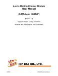
PCI1010 User’s Manual Beijing ART Technology Development Co., Ltd. PCI1010 Motion Control Card Contents Contents ...................................................................................................................................................................................... 2 Chapter 1 Overview .................................................................................................................................................................... 3 1.1 Introduction................................................................................................................................................................... 3 1.2 Features ......................................................................................................................................................................... 3 1.3 Specifications ................................................................................................................................................................ 3 Chapter2 Component Layout ...................................................................................................................................................... 5 2.1 Input/Output Connector ................................................................................................................................................ 5 2.2 Status Light ................................................................................................................................................................... 5 Chapter 3 Pin Layout.................................................................................................................................................................. 6 3.1 Analog Signal Pins ........................................................................................................................................................ 6 3.2 General-purpose Signal Wiring..................................................................................................................................... 7 Chapter 4 Brief Introduction....................................................................................................................................................... 8 Chapter 5 The Description of Functions................................................................................................................................... 11 5.1 Pulse Output Command .............................................................................................................................................. 11 5.1.1 Fixed Driving Output ....................................................................................................................................... 11 5.1.2 Continuous Driving Output.............................................................................................................................. 12 5.2 Acceleration and Deceleration .................................................................................................................................... 12 5.2.1 Constant Speed Driving ................................................................................................................................... 12 5.2.2 S-curve Acceleration/Deceleration Driving ..................................................................................................... 13 5.3 Position Control .......................................................................................................................................................... 14 5.3.1 Logic Position Counter and Real position Counter.......................................................................................... 14 5.3.2 Compare Register and Software Limit............................................................................................................. 14 5.4 Interpolation ................................................................................................................................................................ 15 5.4.1 Linear Interpolation.......................................................................................................................................... 15 5.4.2 Circular Interpolation ....................................................................................................................................... 16 5.4.3 The Bit Pattern Interpolation............................................................................................................................ 17 5.4.4 Constant Vector Speed..................................................................................................................................... 18 5.4.5 Continuous Interpolation.................................................................................................................................. 18 5.4.6 Hardware Limit Signals ................................................................................................................................... 19 5.4.7 Emergency Stop ............................................................................................................................................... 19 Chapter 6 Notes, Warranty Policy ............................................................................................................................................ 20 6.1 Notes ........................................................................................................................................................................... 20 6.2 Warranty Policy........................................................................................................................................................... 20 BUY ONLINE at art-control.com/englishs or CALL 64861583(CN) 2 PCI1010 Motion Control Card Chapter 1 Overview 1.1 Introduction PCI1010 is a 2-axis motion control card which can control 2 axes of either stepper motor or pulse type servo drivers for position, speed, and interpolation controls. 1.2 Features PCI interface, plug and play 2-axis servo/stepper motor control, each axis can work independently. Pulse Output Frequency Error: <0.1% Maximum Pulse Output Speed: 4 MHz Pulse Output Mode: CP/DIR, CW/CCW Non-symmetrical linear acceleration/deceleration drive, S-shaped acceleration/deceleration Constant Speed Driving 2-axis linear interpolation, circular interpolation, bit pattern interpolation, and continuous interpolation. Start/stop multi-axis simultaneously Control acceleration/deceleration time through programmable Read logic position, physic position, drive speed, acceleration, and acceleration/deceleration status in real-time Isolation Voltage: 2500Vrms 1.3 Specifications Control Axis: axes Data Bus: 16 bits Interpolation Functions 2-axes Linear Interpolation Interpolation Range Interpolation Speed Interpolation Accuracy Circular Interpolation Interpolation Range Interpolation Speed Interpolation Accuracy 2 axes Bit Pattern Interpolation Interpolation Speed Related Functions of Interpolation Constant vector speed Continuous interpolation Single step interpolation Each axis −8,388,607 ~ +8,388,607 1~4 MPPS ±0.5 LSB (Within the range of whole interpolation) Each axis −8,388,607 ~ +8,388,607 1~4 MPPS ±1 LSB (Within the range of whole interpolation) 1~4 MPPS (Dependent on CPU data writing time) BUY ONLINE at art-control.com/englishs or CALL 64861583(CN) 3 PCI1010 Motion Control Card Common Specifications of Each Axis Drive Pulses Output (When CLK = 16 MHz) Pulse Output Speed Range 1 ~ 4MPPS Pulse Output Accuracy within ± 0.1% (according to the setting speed) S-curve Jerk 954 ~ 62.5x10⁶ PPS/S2 (Multiple = 1) Accelerating/Decelerating Speed 125 ~ 1 x 10⁶ PPS/S (Multiple = 1) Initial Speed 1 ~ 8,000PPS (Multiple = 1) 500PPS ~ 4×10⁶ PPS (Multiple = 500) Drive Speed 1 ~ 8,000PPS (Multiple = 1) 500PPS ~ 4×10⁶ PPS (Multiple = 500) Output-pulse Number 0 ~ 268,435,455 (fixed drive) Speed Curve Constant speed, linear acceleration, parabola S-curve acceleration/ deceleration drive Fixed Drive Deceleration Mode auto (non-symmetrical trapezoidal acceleration is also allowed)/manual Output-pulse numbers and drive speeds changeable during the driving Independent 2-pulse system or 1-pulse 1-direction system selectable Encoder Input A/B quadrature pulse style or Up/Down pulse style selectable Position Counter Logic Position Counter (for output pulse) range −2,147,483,648 ~ +2,147,483,647 Real Position Counter (for feedback pulse) range −2,147,483,648 ~ +2,147,483,647 Data read and write possible Comparison Register COMP + Register Position comparison range −2,147,483,648 ~ +2,147,483,647 COMP − Register Position comparison range −2,147,483,648 ~ +2,147,483,647 Status and signal outputs for the comparisons of position counters Software limit functioned External Signal for Driving EXPP and EXPM signals for fixed pulse / continuous drive External Deceleration/Sudden Stop Signal STOP0 ~ 2 3 points for each axis Enable/disable and logical levels selectable Servo Motor Input Signal ALARM (Alarm), INPOS (In Position Check) Enable/disable and logical levels selectable General Input/Output Signal IN0~1 two for each axis OUT0~1 two for each axis Limit Signals Input 1 point, for each + and − side Logical levels and decelerating/sudden stop selectable Emergency Stop Signal Input EMG, 1 point in all axes Sudden stop the drive pulse of all axes when on Low level Electrical Characters Operation Temperature 0 ~ +50℃ Power Supply 24V (External) Input Clock Pulse 16,000 MHz (Standard) BUY ONLINE at art-control.com/englishs or CALL 64861583(CN) 4 PCI1010 Motion Control Card Chapter2 Component Layout 2.1 Input/Output Connector CN1: signal input/output connector 2.2 Status Light Power LED: Power indicator BUY ONLINE at art-control.com/englishs or CALL 64861583(CN) 5 PCI1010 Motion Control Card Chapter 3 Pin Layout 3.1 Analog Signal Pins Pin No 1 20 Signal Name XPP/PLS YPP/PLS 2 21 XPM/DIR YPM/DIR 22 3 XECA/PPIN YECA/PPIN 23 4 XECB/PMIN YECB/PMIN 24 29 XINPOS YINPOS 5 10 25 30 XALARM YALARM XLMTP YLMTP 6 11 XLMTM YLMTM 7 12 XSTOP0 YSTOP0 26 31 XSTOP1 YSTOP1 14 35 33 16 XIN1 YIN1 XIN0 YIN0 Description Pulse +/Pulse: + direction dive pulse outputting When the reset is on the Low level, and while the driving is starting, DUTY 50% (at constant speed) of the plus drive pulses are outputting. + or − pulse mode is selectable. When the 1-pulse 1-direction mode is selected, this terminal is for drive output. Pulse −/Pulse: − direction dive pulse outputting When the reset is on the Low level, and while the driving is starting, DUTY 50% (at constant speed) of the plus drive pulses are outputting. + or − pulse mode is selectable. When the 1-pulse 1-direction mode is selected, this terminal is direction signal. Encoder−A/Pulse +in: signal for encoder phase-A input This input signal, together with phase-B signal, will make the Up/Down pulse transformation to be the input count of real position counter. When the Up/Down pulse input mode is selected, this terminal is for UP pulses input. Once the input pulse is up, the real position counter is counting up. Encoder-B/Pulse -in: signal for encoder phase-B input This input signal, together with phase-A signal, will make the Up/Down pulse transformation to be the input count of real position counter. When the Up/Down pulse input mode is selected, this terminal is for DOWN pulses input. Once the input pulse is up, the real position counter is counting down. In-position: input signal for servo driver in-position Enable/disable and logical levels can be set as commands. When “enable” is set, and after the driving is finished, this signal is active and standby. Servo Alarm: input signal for servo driver alarm Enable/disable and logical levels can be set as commands. OVER Limit +: signal of + direction over limit During the + direction drive pulse outputting, decelerating stop or sudden stop will be performed once this signal is active. When the filter function is disabled, the active pulse width must be 2CLK or more. OVER Limit −: signal of − direction over limit During the − direction drive pulse outputting, decelerating stop or sudden stop will be performed once this signal is active. The active pulse width should be more than 2CLK. Decelerating stop/sudden stop and logical levels can be set during the mode selection. input signal to perform decelerating/sudden stop for each axis These signals can be used for HOME searching. The active pulse width should be more than 2CLK. Enable disable and logical levels can be set for STOP0. input signal to perform decelerating/sudden stop for each axis These signals can be used for HOME searching. The active pulse width should be more than 2CLK. Enable disable and logical levels can be set for STOP1. General Input 1/: general purpose input signals General Input 0/: general purpose input signals. BUY ONLINE at art-control.com/englishs or CALL 64861583(CN) 6 PCI1010 Motion Control Card 32 34 13 15 36 XOUT1 YOUT1 XOUT0 YOUT0 XEXPP General Output 1/: general purpose output signals. 37 YEXPP 17 XEXPM 18 YEXPM General Output 0/: general purpose output signals. External Operation +: + direction drive starting signal from external source When the fixed driving is commanded from an external source, +direction driving will start if this signal is down. Otherwise, when the continuous driving is commanded from an external source, + driving will start if this signal is on the Low level. External Operation −: − direction drive starting signal from external source When the fixed driving is commanded from an external source, − direction driving will start if this signal is down. Otherwise, when the continuous driving is commanded from an external source, − driving will start if this signal is on the Low level. Emergency Stop: input signal to perform the emergency stop for all axes When this signal in on the low level, including the interpolation driving, every axis will stop the operation immediately. The low level pulse width should be more than 2CLK. 【Note】For this signal, its logical levels cannot be selected. 19 EMGN 27 VDD 28 24V + 5V Power Terminal + 24V Power Terminal 8~9 OGND Ground (0V) Terminal 3.2 General-purpose Signal Wiring In PCI1010, there are 2 general purpose input pins, nIN1~0 and 2 general output pins, nOUT1~0, for each axis. 24V 2.2K +5V 1K 24V 5V 470Ω Digital Input 4.7K Digital Output External Digital Input Internal Digital Input PCI1010Card Contact-type Digital input PCI1010Digital Output Motor Control Output Wiring Specifications VDD(5V) 5V 470Ω 1K Output Motor Drive Pulse PCI1010 Card VDD(5V) VCC(5V) Output Pulse to Motor Driver 470Ω 1K Encoder Input Pulse External Encoder Input Pulse Encoder Input Pulse BUY ONLINE at art-control.com/englishs or CALL 64861583(CN) 7 PCI1010 Motion Control Card Chapter 4 Brief Introduction ◆ 2-axis drive independently PCI1010 can control four motors movement. Each axis can do fixed speed drive, linear acceleration/deceleration driving, and S-shaped acceleration/deceleration drive. 2-axis performance is the same. ◆ Speed Control The speed range of the pulse output is from 1PPS to 4MPPS for constant speed, trapezoidal or S-curve acceleration/deceleration driving. Speed accuracy of the pulse output is less than ± 0.1% (at CLK=16MHz). The speed of driving pulse output can be freely changed during the driving. ◆ Acceleration/deceleration driving The PCI1010 can control each axis for acceleration/deceleration of constant speed driving, trapezoidal acceleration/deceleration driving (symmetry/non-symmetry), and S-curve acceleration/deceleration. Automatic acceleration/deceleration of linear acceleration fixed speed pulse driving is available and no need to set deceleration starting point by manual. Since a primary linear increase/decrease method is applied for S-curve acceleration/deceleration, the speed curve forms a secondary parabola acceleration/deceleration curve. In S-curve acceleration and deceleration fixed driving, automatic deceleration is available for symmetrical S-curve only and triangle waveforms during S-curve acceleration/deceleration are prevented by a special method. ◆ Linear Interpolation 2 -axis linear interpolation can be performed. The position boundary is between coordinates −8, 388,607 and +8,388,607, and the positioning error is within ± 0.5 LSB (Least Significant Bit). The interpolation speed range is from 1 PPS to 4 MPPS. BUY ONLINE at art-control.com/englishs or CALL 64861583(CN) 8 PCI1010 Motion Control Card ◆ Circular Interpolation Circular interpolation can be performed. The position boundary is between coordinates −8, 388,608 and +8,388,607, and the positioning error is within ± 1 LSB. The interpolation speed range is from 1 PPS to 4 MPPS. ◆ The Bit Pattern Interpolation This interpolation driving receives, for each axis in pulses, interpolation data that was converted to packet (a block of a predetermined amount of data) through the operation by the upper-level CPU and outputs interpolation pulses consecutively at the specified drive speed. This function enables drawing of various loci created by the upper-level CPU. ◆ Continuous Interpolation Different interpolation methods can be used continuously, linear interpolation → circular interpolation → linear interpolation …. The maximum drive speed of performing continuous interpolation is 2 MHz. ◆ Constant Vector Speed Control This function performs a constant vector speed. During the interpolation driving, PCI1010 can set a 1.414 times pulse cycle for 2-axis simultaneous pulse output. ◆ Position Control Each axis has a 32-bit logic position counter and a 32-bits real position counter. The logic position counter counts the number of output pulse, and the real position counter counts the feedback number of pulse from the external encoder or linear scale. BUY ONLINE at art-control.com/englishs or CALL 64861583(CN) 9 PCI1010 Motion Control Card ◆ Compare Register and Software Limit Each axis has two 32-bit compare registers for logical position counter and real position counter. The comparison result can be read from the status registers. The comparison result can be notified by an interrupt signal. These registers can be also functioned as software limits. ◆ Driving By External Pulses It is possible to control each axis by external signals. The +/− direction fixed driving, continuous driving or in manual pulsar mode can be also performed through the external signals. This function is used for JOG or teaching modes, and will share the CPU load. ◆ Servo Motor Feedback Signals Each axis includes input pins for servo feedback signals such as in positioning. ◆ Real Time Monitoring During the driving, the present status such as logical position, real position, drive speed, acceleration/deceleration, status of accelerating/decelerating and constant driving can be read. BUY ONLINE at art-control.com/englishs or CALL 64861583(CN) 10 PCI1010 Motion Control Card Chapter 5 The Description of Functions 5.1 Pulse Output Command There are two kinds of pulse output commands: fixed driving output and continuous driving output. 5.1.1 Fixed Driving Output When host CPU writes a pulse numbers into PCI1010for fixed driving and configures the performance such as acceleration / deceleration and speed, PCI1010 will generate the pulses and output them automatically. Fixed driving operation is performed at acceleration/deceleration, as shown in Fig. 5.1, automatic deceleration starts when the number of pulses becomes less than the number of pulses that were utilized at acceleration, and driving terminates at completion of the output of the specified output pulses. Fig. 5.1 Fixed Driving Changing the Number of Output Pulse in Driving The number of output pulse can be changed in the fixed driving. If the command is for increasing the output pulse, the pulse output profile is shown as Fig. 5.2 or 5.3. If the command is for decreasing the output pulses, the output pulse will be stopped immediately as shown in Fig. 5.4. Furthermore, when in the S-curve acceleration/deceleration driving mode, the output pulse number change will occur to an incomplete deceleration S-curve. Fig. 5.2 Change of Output Pulse Number in Driving Fig. 5.3 Change the Number of Output Pulse During Deceleration Fig. 5.4 Change the Pulse Number Less Than Output Pulse Number BUY ONLINE at art-control.com/englishs or CALL 64861583(CN) 11 PCI1010 Motion Control Card Manual Setting Deceleration for fixed Acceleration/Deceleration Driving As shown in Fig. 5.1, generally the deceleration of fixed acceleration/deceleration driving is controlled automatically by PCI1010. However, in the following situations, it should be preset the deceleration point by the users. • The change of speed is too often in the trapezoidal fixed acceleration/deceleration driving. • When use circular interpolation, bit pattern interpolation and continuous interpolation for acceleration and deceleration. 5.1.2 Continuous Driving Output When the continuous driving is performed, PCI1010 will drive pulse output in a specific speed until stop command or external stop signal is happened. The main application of continuous pulse driving is: home searching, teaching or speed control. The drive speed can be changed freely during continuous driving. Two stop commands are for stopping the continuous driving. One is “decelerating stop”, and the other is “sudden stop”. Three input pins, STOP1~STOP0, of each axis can be connected for external decelerating and sudden stop signals. Enable/disable, active levels and mode setting are possible. Fig. 5.5 Continuous Driving 5.2 Acceleration and Deceleration Basically, driving pulses of each axis are output by a fixed driving command or a continuous driving command of the + direction or – direction. These types of driving can be performed with a speed curve of constant speed, linear acceleration, non-symmetrical linear acceleration, S-curve acceleration/deceleration according to the mode that is set or the operation parameter value. 5.2.1 Constant Speed Driving When the drive speed set in PCI1010 is lower than the initial, the acceleration/deceleration will not be performed, instead, a constant speed driving starts. If the user wants to perform the sudden stop when the home sensor or encoder Z-phase signal is active, it is better not to perform the acceleration/deceleration driving, but the low-speed constant driving from the beginning. For processing constant speed driving, the following parameters will be preset accordingly. BUY ONLINE at art-control.com/englishs or CALL 64861583(CN) 12 PCI1010 Motion Control Card Fig. 5.6 Constant Speed Driving 5.2.2 S-curve Acceleration/Deceleration Driving This card creates an S curve by increasing/reducing acceleration/decelerations in a primary line at acceleration and deceleration of drive speed. Figure 5.7 shows the operation of S-curve acceleration/deceleration. When driving starts, the acceleration increases on a straight line at the specified jerk (K). In this case, the speed data forms a secondary parabolic curve (section a). When acceleration reaches designation value (A), acceleration is maintained. In this case, the speed data forms an increase on a straight line (section b). If the difference between the specified drive speed (V) and the current speed becomes less than the speed that was utilized at the increase of acceleration, the acceleration starts to decrease towards 0. The decrease ratio is the same as the increase ratio and the acceleration decreases in a linear form of the specified jerk (K). In this case, the speed data forms a secondary parabolic curve (section c). Thus, the case that acceleration has a constant part in its acceleration, this book calls it The Partial S curve Acceleration. On the other hand, if the difference between the specified drive speed (V) and the current speed becomes less than the speed that was utilized at the increase of acceleration before acceleration reaches designation value (A), section shifts from a to c without b section. Thus, the case that acceleration does not have a constant part in its acceleration, it calls The Perfect S curve Acceleration. Please refer to example of parameter settings described later and appendix regarding cases of the partial S curve acceleration and the perfect S curve acceleration. Also at the deceleration, the speed forms an S curve by increasing/decreasing the deceleration in a primary linear form (sections d, e and f). The same operation is performed in acceleration/deceleration where the drive speed is changed during continuous driving. Fig. 5.7 S-Curve Acceleration/Deceleration Driving BUY ONLINE at art-control.com/englishs or CALL 64861583(CN) 13 PCI1010 Motion Control Card 5.3 Position Control Fig 5.8 is 1-axis position control block diagram. For each axis, there are two 32 bit up-and-down counters for counting present positions and two comparison registers for comparing the present positions. Fig. 5.8 Position Control Block Diagram 5.3.1 Logic Position Counter and Real position Counter As shown above in Fig. 5.8, the logic position counter is counting the driving pulses in MCX312. When one + direction plus is outputting, the counter will count-up 1; when one - direction pulse is outputting, the counter will count-down 1. The real position counter will count input pulse numbers from external encoder. The type of input pulse can be either A/B quadrature pulse type or Up/Down pulse (CW/CCW) type. Host CPU can read or write these two counters any time. The counters are signed 32 bits, and the counting range is between -2,147,483,648 ~ + 2,147,483,647. The negative is in 2’s complement format. The counter value is random while resetting. 5.3.2 Compare Register and Software Limit Each axis has, as shown in Fig. 5.8, two 32-bit registers which can compare the logical positions with the real positions. The logical position and real position counters are selected by bit D5 (CMPSL) of WR2 register. The main function of COMP+ Register is to check out the upper limit of logical/real position counter. When the value in the logical/real position counters is larger than that of COMP+ Register, bit D0 (CMP+) of register RR1 will become 1. On the other hand, COMP- Register is used for the lower limit of logical/real position counter. When the value of logical/real position counter becomes smaller than hat of COMP+ Register, bit D1 (CMP-) of register RR1 will become 1. BUY ONLINE at art-control.com/englishs or CALL 64861583(CN) 14 PCI1010 Motion Control Card 5.4 Interpolation This 2-axis motion control card can perform linear interpolation, circular interpolation and bit pattern interpolation. In the process of interpolation driving, all the calculations will follow the X axis. So, the user has to set the parameters such as initial speed and drive speed of the X axis before performing the interpolation. After setting all of the parameters for interpolations, and writing the interpolation driving commands to command register WR0, the user can start the interpolation driving. During the interpolation driving, D8 (I-DRV) of main status register RR0 will become 1 during the interpolation, and it will become 0 when the interpolation is finished. Also, during the interpolation driving, the bit D1 (Y-DRV) and D0 (X-DRV) will become 1. The maximum drive speed is 4MPPS for linear, circular or bit pattern interpolation. For continuous interpolation, the maximum drive speed is 2MPPS. Over Limit Error of Interpolation When the hardware limit or the software limit of each axis is active during the interpolation driving, the interpolation will stop. The stop is occurred by errors, RR0 (main status register) will confirm the error bit in D5 (Y-ERR) and D4 (X-EWW). RR0 will become 1 and RR2 (error register) of this axis will be read out. [Note] In case of circular or bit patter interpolation, the “active” of hardware or software limit, in either + or - direction, will stop the interpolation driving. In-position Signal for Servo Motor During the interpolation driving, when the in-position signal (nINP0S) of each X and Y axis is active, and also when the interpolation is finished, the INP0S signal of the axis is stand-by at its active level, and D8 (I-DRV) of RR0 register returns to 0. 5.4.1 Linear Interpolation To execute the linear interpolation, the user can, according to the present point coordinates, set the finish point coordinates and the interpolation segment(s) for 2 axes. Fig. 5.9 shows an example of axis interpolation where linear interpolation is performed from the current coordinates to the finish point coordinates. For individual axis control, the command pulse number is unsigned, and it is controlled by + direction command or − direction command. For interpolation control, the command pulse number is signed. The resolution of linear interpolation is within ±0.5 LSB, as shown in Fig. 5.10 Fig. 5.9 The Position Accuracy for Linear Interpolation As shown in Fig. 2.10, it is an example for pulse output of the linear interpolation driving. We define the longest distance BUY ONLINE at art-control.com/englishs or CALL 64861583(CN) 15 PCI1010 Motion Control Card movement in interpolation is the “long axis”. And the other is “short axis”. The long axis outputs an average pulse train. The driving pulse of the short axis depends on the long axis and the relationship of the two axes. Fig. 5.10 The Example for Pulse Output at Finish Point (X=20, Y=9) The example of linear interpolation for 2 axes Executing linear interpolation drives in X and Y axes from the current position to the finish position (X: +30,000, Y: −20,000). The initial speed = 500PPS, acceleration/deceleration = 40,000PPS/SEC, drive speed = 5,000PPS. 5.4.2 Circular Interpolation 2 axes X and Y are for circular interpolation. The circular interpolation is starting from the current position (start point). After setting the center point of circular, the finish position and the CW or CCW direction, the user can start the circular interpolation. Note: The coordinates setting value is the relative value of the start point coordinates. In Fig. 5.11, it explains the definition of CW and CCW circular interpolations. The CW circular interpolation is starting from the start point to the finish position with a clockwise direction; the CCW circular interpolation is with a counter-clockwise direction. When the finish point is set to (0, 0), a circle will come out. Fig. 5.11 CW/CCW Circular Interpolation BUY ONLINE at art-control.com/englishs or CALL 64861583(CN) 16 PCI1010 Motion Control Card In Fig. 5.12, it explains the long axis and the short axis. First, we define 8 quadrants in the X-Y plane and put the numbers 0~7 to each quadrant. We find the absolute value of X is always larger than that of Y in quadrants 0, 3, 4 and 7, so we call X is the long axis (Y is the short axis) in these quadrants; in quadrants 1, 2, 5 and 6, Y is the long axis (X is the short axis). The short axis will output pulses regularly, and the long axis will output pulses depending on the interpolation calculation. In Fig. 5.13, it is an example to generate a circle with the center point (-11, 0) and the finish point (0, 0). Fig. 5.12 The 0~7Quadrants And Short Fig. 5.13 The Example of Circular Interpolation The Example for CW Circular Interpolation This CW circular interpolation starts from the current point (start point: 0, 0) to the finish point (X: 5000, Y: −5000); the center point is X: 5000, Y: 0. The interpolating speed is constant at 1000PPS in a constant vector speed driving. 5.4.3 The Bit Pattern Interpolation This interpolation driving receives interpolation data that is created by upper-level CPU and transformed to bit patterns in a block of a predetermined size, and outputs interpolation pulses consecutively at the specified drive speed. Every axis has 2 bit-data buffers for host CPU: one for + direction and the other for - direction. When performing the bit pattern interpolation, the host CPU will write the designated interpolation data, for each axis X and Y, into PCI1010. If a bit in the bit pattern data from CPU is “1”, PCI1010 will output a pulse at the time unit; if it is “0”, PCI1010 will not output any pulse at the time unit. For example, if the user wants to generate the X-Y profile (see Fig. 5.14), the host CPU must write a set of pattern into those BUY ONLINE at art-control.com/englishs or CALL 64861583(CN) 17 PCI1010 Motion Control Card specific registers ---- XPP: the + direction register for X axis, XPM: the − direction register for X axis, YPP and YPM: the + and − directions registers. With in the time unit, PCI1010 will check the registers once and decide to output a pulse or not depending on the bit pattern. Fig. 5.14 Example for Bit Pattern Interpolation 5.4.4 Constant Vector Speed PCI1010 is with the constant vector speed control function which can control the resultant speed of two axes to keep the speed in constant. Fig. 5.15 shows the profile of 2 axes interpolation driving. The vector speed reflects 1.414 times of the individual axis drive speed. So, we have to set the speed of 1.414 times to keep the vector speed for 2-axis driving. Fig. 5.15 Example of 2-Axis Interpolation 5.4.5 Continuous Interpolation The continuous interpolation is executing a series of interpolation processes such as linear interpolation → circular interpolation → linear interpolation → ···. During the continuous interpolation, the driving will not stop; contrarily, the pulses are output continuously. When executing the continuous interpolation, the host CPU has to write the next interpolation segment into MCX312 before the previous interpolation segment is finished. BUY ONLINE at art-control.com/englishs or CALL 64861583(CN) 18 PCI1010 Motion Control Card Attentions for Continuous Interpolation a. Before setting the interpolation segment, the user should first set other data such as center point, finish point… for each segment. b. The maximum speed for the continuous interpolation is 2MHz. c. The following interpolation segment must be loaded before the previous interpolation segment is finished. d. The segment driving time should be longer than the time for error checking and the command setting of next segment during the interpolation. e. In continuous interpolation, if one of 2/3 axes is 0, interpolation is performed correctly, otherwise, 0 cannot be set to the finish point of all axes in 2/3 axes linear interpolation, or to the center point of both axes in circular interpolation, any axis cannot set the data that drive pulse is not output. If suchlike data it set, interpolation cannot be performed correctly. 5.4.6 Hardware Limit Signals Hardware limit signals, nLMTP and nLMTM, are used for stopping the pulse output if the limit sensors of + and − directions are triggered. 5.4.7 Emergency Stop Signal EMGN is able to perform the emergency stop function for both X and Y axes during the driving. Normally, this signal is kept on the Hi level. When it is falling to the Low level, all axes will stop immediately, and the D5 (EMG) bit of register RR2 (each axis) becomes 1. Please be noted that there is no way to select the logical level of EMGN signal. BUY ONLINE at art-control.com/englishs or CALL 64861583(CN) 19 PCI1010 Motion Control Card Chapter 6 Notes, Warranty Policy 6.1 Notes In our products’ packing, user can find a user manual, a PCI1010 module and a quality guarantee card. Users must keep quality guarantee card carefully, if the products have some problems and need repairing, please send products together with quality guarantee card to ART, we will provide good after-sale service and solve the problem as quickly as we can. When using PCI1010, in order to prevent the IC (chip) from electrostatic harm, please do not touch IC (chip) in the front panel of PCI1010 module. 6.2 Warranty Policy Thank you for choosing ART. To understand your rights and enjoy all the after-sales services we offer, please read the following carefully. 1. Before using ART’s products please read the user manual and follow the instructions exactly. When sending in damaged products for repair, please attach an RMA application form which can be downloaded from: www.art-control.com. 2. All ART products come with a limited two-year warranty: ¾ The warranty period starts on the day the product is shipped from ART’s factory ¾ For products containing storage devices (hard drives, flash cards, etc.), please back up your data before sending them for repair. ART is not responsible for any loss of data. ¾ Please ensure the use of properly licensed software with our systems. ART does not condone the use of pirated software and will not service systems using such software. ART will not be held legally responsible for products shipped with unlicensed software installed by the user. 3. Our repair service is not covered by ART's guarantee in the following situations: ¾ Damage caused by not following instructions in the User's Manual. ¾ Damage caused by carelessness on the user's part during product transportation. ¾ Damage caused by unsuitable storage environments (i.e. high temperatures, high humidity, or volatile chemicals). ¾ Damage from improper repair by unauthorized ART technicians. ¾ Products with altered and/or damaged serial numbers are not entitled to our service. 4. Customers are responsible for shipping costs to transport damaged products to our company or sales office. 5. To ensure the speed and quality of product repair, please download an RMA application form from our company website. BUY ONLINE at art-control.com/englishs or CALL 64861583(CN) 20