1
2-axis Motion Control Module
User Manual
(I-8092F)
(Version 2.3)
Macro Function Library in C++ for
WinCon and I-8000 series PAC controllers
ICPDAS
1
I-8092F Software User Manual
Warranty
All products manufactured by ICPDAS Inc. are warranted against defective
materials for a period of one year from the date of delivery to the original
purchaser.
Warning
ICPDAS Inc. assumes no liability for damages consequent to the use of this
product. ICPDAS Inc. reserves the right to change this manual at any time without
notice. The information furnished by ICPDAS Inc. is believed to be accurate and
reliable. However, no responsibility is assumed by ICPDAS Inc. for its use, or for
any infringements of patents or other rights of third parties resulting from its use.
Copyright
Copyright 1997-2005 by ICPDAS Inc., LTD. All rights reserved worldwide.
Trademark
The names used for identification only maybe registered trademarks of their
respective companies.
License
The user can use, modify and backup this software on a single machine. The
user may not reproduce, transfer or distribute this software, or any copy, in whole
or in part.
ICPDAS
2
I-8092F Software User Manual
INDEX
1 PREFACE ............................................................................ 7
1.1 Introduction................................................................................................ 7
1.2 Basic and Macro functions........................................................................ 7
1.3 Funciton description .................................................................................. 8
2 BASIC SETTINGS.............................................................. 9
2.1 Code numbers for axes .............................................................................. 9
2.2 Registration of Modules and getting the LIB version ............................ 9
2.3 Resetting Module ..................................................................................... 12
2.4 Pulse Output Mode Setting ..................................................................... 12
2.5 Setting the Maximum Speed ................................................................... 13
2.6 Setting the Active Level of the Hardware Limit Switches ................... 14
2.7 Setting the Motion Stop Method When Limit Switch Is Sensed ......... 15
2.8 Setting the Trigger Level of the NHOME Sensor ................................. 15
2.9 Setting Trigger Level of the Home sensor ............................................. 16
2.10 Setting and Clearing the Software Limits ........................................... 16
2.11 Setting the Encoder Related Parameters ............................................. 17
2.12 Setting the Servo Driver (ON/OFF) ..................................................... 18
2.13 Setting the SERVO ALARM Function ................................................ 19
2.14 Setting the Active Level of the In-Position Signals ............................. 20
2.15 Setting the Time Constant of the Digital Filter................................... 20
2.16 Position Counter Variable Ring............................................................ 22
2.17 Triangle prevention of fixed pulse driving .......................................... 23
2.18 External Pulse Input.............................................................................. 24
2.18.1 Handwheel (Manual Pulsar) Driving ..............................................................24
2.18.2 Fixed Pulse Driving Mode ..............................................................................25
2.18.3 Continuous Pulse Driving Mode....................................................................26
2.18.4 Disabling the External Signal Input Functions.............................................27
2.19 Configure hardware with pre-defined configuration file................... 28
3 READING AND SETTING THE REGISTERS............. 29
3.1 Setting and Reading the Command Position (LP)................................ 29
3.2 Setting and Reading the Encoder Counter............................................ 30
3.3 Reading the Current Velocity ................................................................. 31
3.4 Reading the Current Acceleration.......................................................... 31
3.5 Reading the DI Status .............................................................................. 32
3.6 Reading and Clearing the ERROR Status ............................................ 34
3.7 Setting the general Dinigtal output ........................................................ 35
ICPDAS
3
I-8092F Software User Manual
4 FRNET FUNCTIONS (FOR I8092F ONLY).................. 36
4.1 Read FRnet DI Signals ............................................................................ 36
4.2 Write data to FRnet DO .......................................................................... 37
5 AUTO HOMING ............................................................... 38
5.1 Setting the Homing Speed ....................................................................... 38
5.2 Using an Limit Switch as the HOME sensor......................................... 39
5.3 Setting the Homing Mode........................................................................ 39
5.4 Starting the Homing Sequence ............................................................... 41
5.5 Waiting for the Homing sequence to be Completed ............................. 41
6 GENERAL MOTION CONTROL.................................. 42
6.1 Independent Axis Motion Control.......................................................... 42
6.1.1 Setting the Acceleration/Deceleration Mode ..................................................42
6.1.2 Setting the Start Speed.....................................................................................44
6.1.3 Setting the Desired Speed................................................................................44
6.1.4 Setting the Acceleration ...................................................................................45
6.1.5 Setting the Deceleration ...................................................................................45
6.1.6 Setting the Acceleration Rate ..........................................................................47
6.1.7 Setting the Value of the Remaining Offset Pulses .........................................48
6.1.8 Fixed Pulse Output ...........................................................................................49
6.1.9 Continuous Pulse Output.................................................................................50
6.2 Interpolation Commands ........................................................................ 51
6.2.1 Setting the Speed and Acc/Dec Mode for Interpolation ................................51
6.2.2 Setting the Vector Starting Speed ...................................................................55
6.2.3 Setting the Vector Speed..................................................................................55
6.2.4 Setting the Vector Acceleration .......................................................................56
6.2.5 Setting the Vector Deceleration Value.............................................................57
6.2.6 Setting the Vector Acceleration Rate ..............................................................58
6.2.7 Setting the Number of the Remaining Offset Pulses .....................................59
6.2.8 2-Axis Linear Interpolation Motion ..................................................................60
6.2.9 2-Axis Circular Interpolation Motion (an Arc).................................................61
6.2.10 2-Axis Circular Interpolation Motion .............................................................63
6.3 Continuous Interpolation ........................................................................ 65
6.3.1 2-Axis Rectangular Motion ...............................................................................65
6.3.2 2-Axis Continuous Linear Interpolation..........................................................66
6.3.3 Multi-Segment Continuous Interpolation (Using Array) ................................68
6.3.4 2-Axis Ratio Motion...........................................................................................69
6.3.5 Mixed Linear and Circular 2-axis motions in Continuous Interpolation ......71
6.4 Set the Interrupt Factors......................................................................... 74
6.4.1 Set the Interrupt Factors ..................................................................................74
6.4.2 Interrupt Disabled .............................................................................................76
6.4.3 Read the Interrupt Occurrence ........................................................................77
6.5 Other functions......................................................................................... 78
ICPDAS
4
I-8092F Software User Manual
6.5.1 Holding the Driving Command ........................................................................78
6.5.2 Release the Holding Status, and Start the Driving.........................................78
6.5.3 Waiting until the Motion Is Completed ............................................................79
6.5.4 Stopping the Axes.............................................................................................81
6.5.5 Clear the Stop Status ........................................................................................85
6.5.6 End of Interpolation ..........................................................................................85
6.5.7 Setting the COMPARE value ............................................................................86
APPENDIX A (I-8092F BASIC FUNCTIONS) ................. 87
A.1 i8092F Command Set.............................................................................. 87
A.2 Pulse Output Command ......................................................................... 88
A.2.1 Signal Types......................................................................................................88
A.2.2 Fixed Pulse Driving ..........................................................................................90
A.2.3 Changing Output Pulse Numbers in Driving .................................................90
A.2.4 Offset Setting for Acceleration/Deceleration Driving....................................90
A.2.5 Continuous Drive Pulse Output ......................................................................92
A.2.6 Constant Speed Driving ...................................................................................93
A.3 Profile Acceleration/Deceleration Planning.......................................... 94
A.3.1 Trapezoidal Driving [Symmetric].....................................................................94
A.3.2 Trapezoidal Driving [Asymmetric] ..................................................................96
A.3.3 Triangle Prevention ..........................................................................................98
A.3.4 S-curve Acceleration / Deceleration [Symmetry]...........................................99
A.4 Pulse Output Commands ..................................................................... 103
A.4.1 2-Axes Interpolation .......................................................................................103
A.4.2 Circular Interpolation .....................................................................................104
A.4.3 Bit Pattern Interpolation.................................................................................107
A.4.4 Continuous Interpolation...............................................................................109
A.5 Automatic Home Search....................................................................... 111
A.6 Interrupt Control .................................................................................. 112
A.6.1 Interrupt for Independent axis.......................................................................112
A.6.2 Interrupt for Interpolation .............................................................................. 112
A.7 I-8092F Function Library .................................................................... 113
A.7.1 Register management functions...................................................................114
A.7.2 Functions for Initial Setting ...........................................................................121
A.7.3 Motion Status Management Functions.........................................................127
A.7.4 Basic Motion Command Functions ..............................................................134
A.7.5 Interpolation Functions..................................................................................145
A.7.6 Automatic Home Search ................................................................................158
A.7.7 Interrupt Function...........................................................................................170
A.7.8 FRnet Related Functions ...............................................................................177
A.8 i8092 Command Lists ........................................................................... 179
A.8.1 Data Setting Commands ................................................................................179
A.8.2 Data Reading Commands ..............................................................................179
A.8.3 Driving Commands.........................................................................................180
A.8.4 Interpolation Commands ...............................................................................180
A.8.5 Other commands ............................................................................................180
ICPDAS
5
I-8092F Software User Manual
APPENDIX B: MCX312 REGISTERS............................ 181
B.1 Command Register: WR0 .................................................................... 181
B.2 Mode Register1: WR1........................................................................... 182
B.3 Mode Register2: WR2........................................................................... 184
B.4 Mode Register3: WR3........................................................................... 186
B.5 Output Register: WR4 .......................................................................... 189
B.7 Data Register: WR6/WR7 .................................................................... 190
B.8 Main Status Register: RR0................................................................... 190
B.9 Status Register 1: RR1 .......................................................................... 191
B.10 Status Register 2: RR2 ........................................................................ 193
B.11 Status Register 3: RR3 ........................................................................ 194
B.12 Input Register: RR4 / RR5 ................................................................. 195
B.13 Data-Read Register: RR6 / RR7 ........................................................ 195
ICPDAS
6
I-8092F Software User Manual
1 Preface
1.1 Introduction
This manual provides complete and detailed description of i8092F functions
for users to develop programs for their control of automatic equipments.
Many examples are included in this manual for reference to write efficient
application programs.
This manual includes six chapters and two appendices. This chapter gives a
brief description of this manual. Chapter 2 to 6 is the explanations of macro
functions (MF). Appendices A and B are the descriptions of basic functions
(BF) and the registers of MCX312, respectively.
The functions defined in DLL file are explained here. This DLL can be used on
different developing software platforms, such as eVC++, VB.net, and C#.net,
and different OS systems ( MiniOS7 / WinCE).
1.2 Basic and Macro functions
Basic functions are suitable for those who are familiar with the MCX312
motion chip. These functions can directly read/write the registers of motion
chip. However, users need to know more details about this motion chip.
Macro functions provide a set of much easy-to-use functions that simplify the
programming for users. Some necessary settings, such as speed range and
deceleration point, are calculated inside those functions to ease the loading of
users on having to understand the motion chip. Some useful costumed
functions are provided for users to develop applications efficiently.
If possible, do not mix these two groups of functions together. Some internal
parameters may be changed beyond users'consideration.
ICPDAS
7
I-8092F Software User Manual
1.3 Funciton description
All functions are listed in following form:
Function_name (parameter1, parameter2, …)
Description:
Explanation of this function.
Parameters:
Definitions of the parameters and how to use them.
Return:
The return value of this function.
Example:
Simple example program in C++.
Remark:
Comments.
ICPDAS
8
I-8092F Software User Manual
2 Basic Settings
2.1 Code numbers for axes
The axis assignments follow the definitions listed below: X=1, Y=2. If X and Y
axes are assigned simultaneously, then the code number is 3. An assignment for
either single axis or multiple axes at the same time is possible. Available axis
code numbers are listed below. The type of the axis argument used in the
functions is defined as WORD.
Table 2-1 Axis assignments and their corresponding codes
Axis
X
Y
XY
Code
0x1
0x2
0x3
Name
AXIS_X
AXIS_Y
AXIS_XY
2.2 Registration of Modules and getting the LIB version
BYTE i8092MF_REGISTRATION(BYTE cardNo, BYTE slot)
Description:
This function registers a module that is installed in slot number, slot, by
assigning a card number. Registration must be performed for each I-8092F
motion control module before other functions are called. After registration,
each module can be identified by its corresponding module number.
Parameters:
cardNo:
slot:
Module number
Slot number
for I-8000: 0~7
for WinCon-8000: 1~7
Return:
YES
NO
Normal
Abnormal
Example:
//================= for WinCon-8000 ==================
ICPDAS
9
I-8092F Software User Manual
//set each module number the same as the slot number, respectively.
//(slot1 ~ slot7)
BYTE cardNo;
BYTE slot;
int Found = 0;
for (slot = 1; slot < 8; slot++)
{
cardNo = slot;
if (i8092MF_REGISTRATION(cardNo, slot) == YES)
{ //slot number begins from 1.
//if a module is found, then it is registered as its slot number.
i8092MF_RESET_CARD(cardNo);
Found++;
}
}
if (Found == 0)
{
//if Wincon cannot find any I-8092F module,
//please add codes to handle the exception here.
return;
}
//=================== for I-8000 ===================
//set the module number the same as the slot number, respectively.
//(slot1 ~ slot7)
BYTE cardNo;
BYTE slot;
int Found = 0;
for (slot = 0; slot < 8; slot++)
{
cardNo = slot + 1;
//slot number begins from 0, but module number begin from 1.
if (i8092MF_REGISTRATION(cardNo, slot) == YES)
{
//if a module is found, then it is registered by giving a number.
i8092MF_RESET_CARD(cardNo);
Found++;
}
}
if (Found == 0)
{
//if Wincon cannot find any I-8092F module,
//please add codes to handle the exception here.
return;
}
ICPDAS
10
I-8092F Software User Manual
WORD i8092MF_GET_VERSION(void)
Description:
Read the version of current i8092 library.
Parameters:
cardNo:
Module number
Return:
Version code:
including information of the year and the month:
0x0000 ~ 0x9999
Example:
WORD VER_No;
VER_No = i8092MF_GET_VERSION();
//Read the version code of i8092.dll
Remark:
If the return value is 0x0607
06 : the year is 2006
07: the month is July.
ICPDAS
11
I-8092F Software User Manual
2.3 Resetting Module
void i8092MF_RESET_CARD(BYTE cardNo)
Description:
This function resets module using a software command.
Parameters:
cardNo:
Module number
Return:
None
Example:
i8092MF_RESET_CARD(1);
//Reset module 1.
2.4 Pulse Output Mode Setting
void i8092MF_SET_PULSE_MODE(BYTE cardNo, WORD axis, BYTE nMode)
Description:
This function sets the pulse output mode as either CW/CCW or PULSE/DIR
for the assigned axes and their direction definition.
Parameters:
cardNo:
axis:
nMode:
Module number
Axis or axes (Please refer to Table 2-1)
Assigned mode (Please refer to Table 2-2)
Return:
None
Example:
i8092_SET_PULSE_MODE(1, AXIS_XYZ, 2);
//set the pulse mode of X, Y, and Z axes as mode 2
i8092_SET_PULSE_MODE(1, AXIS_U, 3);
//set the pulse mode of U axis as mode 3
ICPDAS
12
I-8092F Software User Manual
Table 2-2 A List of pulse output modes
mode
CW / CCW
PULSE / DIR
Pulse output signals
nPP
nPM
0
CW (rising edge)
CCW (rising edge)
1
CW (falling edge)
CCW (falling edge)
2
PULSE (rising edge)
3
PULSE (falling edge)
4
PULSE (rising edge)
5
PULSE (falling edge)
DIR
(LOW:+dir/ HIGH:-dir)
DIR
(LOW:+dir/ HIGH:-dir)
DIR
(HIGH:+dir/ LOW:-dir)
DIR
(HIGH:+dir/ LOW:-dir)
2.5 Setting the Maximum Speed
void i8092MF_SET_MAX_V(BYTE cardNo, WORD axis, DWORD data)
Description:
This function sets the maximum rate for the output pulses (speed). A
larger value will cause a rougher resolution. For example, when the
maximum speed is set as 8000 PPS, the resolution is 1 PPS; when the
maximum speed is set as 16000 PPS, the resolution is 2 PPS; when
maximum speed is set as 80000 PPS, the resolution is 10 PPS, etc. The
maximum value is 4,000,000 PPS, which means the resolution of speed
will be 500 PPS. This function change the resolution of speed to reach the
desired maximum speed. Since the scale in hardware is changed, other
parameters will be influenced too, such as the starting speed, the
acceleration, and the jerk. It is recommended to set the maximum speed
value as a integral multiplier of 8000.
Parameters:
cardNo:
axis:
data:
Module number
Axis or axes (Please refer to Table 2-1)
The assigned maximum speed of each axis when the
controller performs an interpolation motion. However, setting
the value of axis 1 is enough. For axis 1, the maximum value
is 4,000,000 PPS.
Return:
None
ICPDAS
13
I-8092F Software User Manual
Example:
i8092MF_SET_MAX_V(1, AXIS_XY, 200000L);
//The maximum speed for the X and Y axes of module 1 is 200KPPS.
//The resolution of the speed will be 200000/8000 = 25 PPS.
2.6 Setting the Active Level of the Hardware Limit Switches
void i8092MF_SET_HLMT(BYTE cardNo, WORD axis, BYTE nFLEdge,
BYTE nRLEdge)
Description:
This function sets the active logic level of the hardware limit switch inputs.
Parameters:
cardNo:
axis:
nFLEdge:
nRLEdge:
Module number
Axis or axes (Please refer to Table 2-1)
Active level setting for the forward limit switch.
0 = low active; 1 = high active
Active level setting for the reverse limit switch.
0 = low active; 1 = high active
Return:
None
Example:
i8092MF_SET_HLMT(1, AXIS_XY, 0, 0);
//set all the trigger levels as low-active for all limit switches
//on module 1.
ICPDAS
14
I-8092F Software User Manual
2.7 Setting the Motion Stop Method When Limit Switch Is
Sensed
void i8092MF_LIMITSTOP_MODE (BYTE cardNo, WORD axis, BYTE nMode)
Description:
This function sets the motion stop mode of the axes when the
corresponding limit switches are detected.
Parameters:
cardNo:
axis:
nMode:
Module number
Axis or axes (Please refer to Table 2-1)
0: stop immediately; 1: decelerating to stop
Return:
None
Example:
i8092MF_LIMITSTOP_MODE(1, AXIS_X, 0);
//set X axis to stop immediately if any limit switch on X axis is triggered.
2.8 Setting the Trigger Level of the NHOME Sensor
void i8092MF_SET_NHOME(BYTE cardNo, WORD axis, BYTE nNHEdge)
Description:
This function sets the trigger level of the near home sensor (NHOME).
Parameters:
cardNo:
axis:
nNHEdge:
Module number
Axis or axes (Please refer to Table 2-1)
Active level setting for the near home sensor.
0 = low active;
1 = high active
Return:
None
Example:
i8092MF_SET_NHOME(1, AXIS_XY, 0);
//set the trigger level of NHOME of X and Y axes on module 1 to be active low.
ICPDAS
15
I-8092F Software User Manual
2.9 Setting Trigger Level of the Home sensor
void i8092MF_SET_HOME_EDGE(BYTE cardNo, WORD axis, BYTE nHEdge)
Description:
This function sets the trigger level of the home sensor (HOME).
Parameters:
cardNo:
axis:
nHEdge:
Module number
Axis or axes (Please refer to Table 2-1)
Active level setting for the home sensor.
0 = low active; 1 = high active
Return:
None
Example:
i8092MF_SET_HOME_EDGE(1, AXIS_XY, 1);
//set the trigger level as high active for all home sensors on module 1.
2.10 Setting and Clearing the Software Limits
void i8092MF_SET_SLMT(BYTE cardNo, WORD axis, long dwFL, long dwRL,
BYTE nType)
Description:
This function sets the software limits.
Parameters:
cardNo:
axis:
dwFL:
dwRL:
nType:
Module number
Axis or axes (Please refer to Table 2-1)
Value of the forward software limit
(-2,147,483,648 ~ +2,147,483,647)
Value of the reverse software limit
(-2,147,483,648 ~ +2,147,483,647)
Position counter to be compared:
0 = logical position counter (LP), i.e., the command position
1 = encoder position counter (EP), i.e., the real position
Return:
None
ICPDAS
16
I-8092F Software User Manual
Example:
i8092MF_SET_SLMT(1, AXIS_XY, 20000, -3000, 0);
//set the forward software limit as 20000 and the reverse
//software limit as -3000 for all axes on module 1.
void i8092MF_CLEAR_SLMT(BYTE cardNo, WORD axis)
Description:
This function clears the software limits.
Parameters:
cardNo:
axis:
Module number
Axis or axes (Please refer to Table 2-1)
Return:
None
Example:
i8092MF_CLEAR_SLMT(1, AXIS_XY);
//clear the software limits for all axes on module 1.
2.11 Setting the Encoder Related Parameters
void i8092MF_SET_ENCODER(BYTE cardNo, WORD axis, BYTE nMode,
BYTE nDivision, BYTE nZEdge)
Description:
This function sets the encoder input related parameters.
Parameters:
cardNo:
axis:
nMode:
nDivision:
nZEdge:
ICPDAS
Module number
Axis or axes (Please refer to Table 2-1)
Encoder input type: 0 = A quad B; 1 = up/down
Division setting for A quad B input signals:
0 = 1/1
1 = 1/2
2 = 1/4
Sets the trigger level for the Z phase
0 = low active; 1 = high active
17
I-8092F Software User Manual
Return:
None
Example:
i8092MF_SET_ENCODER(1, AXIS_XY, 0, 0, 0);
//set the encoder input type as A quad B; the division is 1;
//and the Z phase is low active.
void i8092MF_SET_EN_DIR(BYTE cardNo, WORD axis, BYTE nDir)
Description:
This function sets the encoder input direction.
Parameters:
cardNo:
axis:
nDir:
Return:
None
Module number
Axis or axes (Please refer to Table 2-1)
Encoder input direction: 0=positive dir; 1= negative dir
Example:
i8092MF_SET_EN_DIR(1, AXIS_XY, 0);
//set the encoder input direction to positive direction;
2.12 Setting the Servo Driver (ON/OFF)
void i8092_SERVO_ON(BYTE cardNo, WORD axis)
Description:
This function outputs a DO signal (ENABLE) to enable the motor driver.
Parameters:
cardNo:
axis:
Module number
Axis or axes (Please refer to Table 2-1)
Return:
None
Example:
i8092_SERVO_ON(1, AXIS_XY);
//enables all drivers on module 1.
ICPDAS
18
I-8092F Software User Manual
void i8092_SERVO_OFF(BYTE cardNo, WORD axis)
Description:
This function outputs a DO signal (ENABLE) to disable the motor driver.
Parameters:
cardNo:
axis:
Module number
Axis or axes (Please refer to Table 2-1)
Return:
None
Example:
i8092_SERVO_OFF(1, AXIS_XY);
//disables all drivers on module 1.
2.13 Setting the SERVO ALARM Function
void i8092MF_SET_ALARM(BYTE cardNo, WORD axis, BYTE nMode,
BYTE nAEdge)
Description:
This function sets the ALARM input signal related parameters.
Parameters:
cardNo:
axis:
nMode:
nAEdge:
Module number
Axis or axes (Please refer to Table 2-1)
Mode: 0 = disable ALARM function;
1 = enable ALARM function
Sets the trigger level
0 = low active; 1 = high active
Return:
None
Example:
i8092MF_SET_ALARM(1, AXIS_XY, 1, 0);
//enable the ALARM for X and Y axes on module 1 and set them
//as low-active.
ICPDAS
19
I-8092F Software User Manual
2.14 Setting the Active Level of the In-Position Signals
void i8092MF_SET_INPOS(BYTE cardNo, WORD axis, BYTE nMode,
BYTE nIEdge)
Description:
This function sets the INPOS input signal related parameters.
Note: Sometimes, this signal is used to connect the SERVO READY input
signal. Users should take care of what signal the daughter board is
wired.
Parameters:
cardNo:
axis:
nMode:
nlEdge:
Module number
Axis or axes (Please refer to Table 2-1)
Mode: 0 = disable INPOS input;
1 = enable INPOS input
Set the trigger level
0 = low active; 1 = high active
Return:
None
Example:
i8092MF_SET_INPOS(1, AXIS_X, 1, 0);
//enable the INPOS function of the X axis on module 1 and set it to be low-active.
Note:
Please refer to the example shown in Fig. 2.12 for wiring of the general DI
input.
2.15 Setting the Time Constant of the Digital Filter
void i8092MF_SET_FILTER(BYTE cardNo, WORD axis, WORD FEn, WORD FLn)
Description:
This function selects the axes and sets the time constant for digital filters of
the input signals.
Parameters:
cardNo:
axis:
FEn:
ICPDAS
Module number
Axis or axes (Please refer to Table 2-1)
Enabled filters. The sum of the code numbers (0~31) are used
to select input signals. Please refer to the following table.
20
I-8092F Software User Manual
Code number
1
2
4
8
16
FLn:
Enabling filters
EMG, nLMTP, nLMTM, nIN0, nIN1
nIN2
nINPOS, nALARM
nEXPP, nEXPM, EXPLSN
nIN3
Sets the filter time constant (0~7) as follows.
Code Removable max. noise width Input signal delay time
0
1.75 μ SEC
2 μ SEC
1
224 μ SEC
256 μ SEC
2
448 μ SEC
512 μ SEC
3
896 μ SEC
1.024mSEC
4
1.792mSEC
2.048mSEC
5
3.584mSEC
4.096mSEC
6
7.168mSEC
8.192mSEC
7
14.336mSEC
16.384mSEC
Return:
None
Example:
i8092MF_SET_FILTER(1, AXIS_XY, 21, 3);
//set the filter time constants of X and Y axes as 1.024mSEC.
//These filters include EMG, nLMTP, nLMTM, nIN0, nIN1, nINPOS, nALARM,
//and nIN3.
//(21 = 1+4+16)
1: EMG + nLMP + nLMPM + nIN0 + nIN1;
//
4: nINPOS + nALARM;
//
16: nIN3.
Note:
ICPDAS
The default wiring design is: nIN0 is connected to the NEAR HOME
(NHOME) sensors; nIN1 is connected to the HOME sensors; and nIN2 is
connected to the index of Encoder input (Z phase).
21
I-8092F Software User Manual
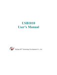
2.16 Position Counter Variable Ring
void i8092MF_VRING_ENABLE(BYTE cardNo, WORD axis, DWORD nVRing)
Description:
This function enables the linear counter of the assigned axes as variable ring
counters.
Parameters:
cardNo:
axis:
nVRing:
Module number
Axis or axes (Please refer to Table 2-1)
Maximum value of the ring counter
(-2,147,483,648 ~ +2,147,483,647)
Return:
None
Example:
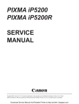
i8092MF_ VRING_ENABLE(1, AXIS_X, 9999);
//set the X axis of module 1 to be a ring counter. The encoder
//values will be 0 to 9999.
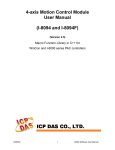
The encoder value is 0 to 9999. When the
counter value reach 9999, an adding pulse
will cause the counter to reset to 0. When the
counter value is 0, a lessening pulse will let
the counter set to 9999.
Max. ring encoder value = 9999
Note:
1. This function will set the LP and EP simultaneously.
2. If this function is enabled, the software limit function cannot be used.
void i8092MF_VRING_DISABLE(BYTE cardNo, WORD axis)
Description:
This function disables the variable ring counter function.
Parameters:
cardNo:
axis:
Module number
Axis or axes (Please refer to Table 2-1)
Return:
None
ICPDAS
22
I-8092F Software User Manual
Example:
i8092MF_ VRING_DISABLE(1, AXIS_X);
//disable the ring counter function for the X axis
//on module 1.
2.17 Triangle prevention of fixed pulse driving
void i8092MF_AVTRI_ENABLE (BYTE cardNo, WORD axis)
Description:
This function prevents a triangle form in linear acceleration (T-curve) fixed
pulse driving even if the number of output pulses is low.
Parameters:
cardNo:
axis:
Module number
Axis or axes (Please refer to Table 2-1)
Return:
None
Example:
i8092MF_ AVTRI_ENABLE(1, AXIS_X);
//set the X axis of module 1 not to generate a triangle form in its speed profile.
void i8092MF_AVTRI_DISABLE (BYTE cardNo, WORD axis)
Description:
This function disable the function that prevents a triangle form in linear
acceleration fixed pulse driving.
Parameters:
cardNo:
axis:
Module number
Axis or axes (Please refer to Table 2-1)
Return:
None
Example:
i8092MF_ AVTRI_DISABLE(1, AXIS_X);
//enable the X axis of module 1 to generate a triangle form in its
//speed profile if the pulse number for output is too low.
ICPDAS
23
I-8092F Software User Manual
2.18 External Pulse Input
2.18.1 Handwheel (Manual Pulsar) Driving
void i8092MF_EXD_MP(BYTE cardNo, WORD axis, long data)
Description:
This function outputs pulses according to the input pulses from a handwheel.
Parameters:
cardNo:
axis:
data:
Module number
Axis or axes (Please refer to Table 2-1.)
The axis can be either X and Y
Gain (a multiplier)
Return:
None
Example:
i8092MF_EXD_MP(1, AXIS_X, 1);
//Each time the handwheel inputs a pulse to the X axis
//on module 1, the controller will output 1 pulses to the motor driver.
i8092MF_EXD_MP(1, AXIS_X, 2);
//Each time the handwheel inputs a pulse to the X axis
//on module 1, the controller will output 2 pulses to the motor driver.
ICPDAS
24
I-8092F Software User Manual
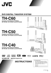
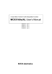
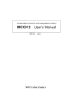
2.18.2 Fixed Pulse Driving Mode
void i8092MF_EXD_FP(BYTE cardNo, WORD axis, long data)
Description:
This function outputs fixed pulses according to the trigger input (the falling
edge of the nEXP+ signal) from a handwheel.
Parameters:
cardNo:
axis:
data:
Module number
Axis or axes (Please refer to Table 2-1.)
The axis can be either X and Y
Number of fixed pulses.
Return:
None
Example:
i8092MF_EXD_FP(1, AXIS_X, 5);
//Each time the controller detects a falling edge of an XEXP+
//signal, it will output 5 pulses to the X axis.
Example of fixed pulse driving using an external signal
ICPDAS
25
I-8092F Software User Manual
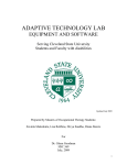
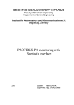
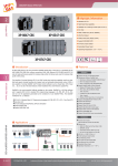
2.18.3 Continuous Pulse Driving Mode
void i8092MF_EXD_CP(BYTE cardNo, WORD axis, long data)
Description:
The controller will continuously output pulses in positive direction if the
falling edge of nEXP+ signal from a handwheel is detected. Conversely, it will
continuously output pulses in negative direction if the falling edge of nEXP- signal
is detected.
Parameters:
cardNo:
axis:
data:
Module number
Axis or axes (Please refer to Table 2-1.)
The axis can be either X and Y
Pulse output speed in PPS
Return:
None
Example:
i8092MF_EXD_CP(1, AXIS_X, 20);
//Each time the controller detects a falling edge of an XEXP+
//signal, it will continuously drive X axis at the speed of 20 PPS.
Continuous driving using an external signal
ICPDAS
26
I-8092F Software User Manual
2.18.4 Disabling the External Signal Input Functions
void i8092MF_EXD_DISABLE(BYTE cardNo, WORD axis)
Description:
This function turns off the external input driving control functions.
Parameters:
cardNo:
axis:
Module number
Axis or axes (Please refer to Table 2-1.)
The axis can be either X and Y
Return:
None
Example:
i8092MF_EXD_DISABLE(1, AXIS_X);
//disable the external input driving control function
//of X axis on module 1
ICPDAS
27
I-8092F Software User Manual
2.19 Configure hardware with pre-defined configuration
file
short i8092MF_ LOAD_CONFIG (BYTE cardNo)
Description:
This function loads the pre-defined configuration file and set the target I8092
module automatically. The configuration file is generated by the PACEzGo.
Parameters:
cardNo:
Module number
Return:
0: successfully
-1: cannot open the pre-defined configuration file.
Example:
i8092MF_ LOAD_CONFIG (1);
//load the configuration file and configure the module 1.
ICPDAS
28
I-8092F Software User Manual
3 Reading and Setting the Registers
3.1 Setting and Reading the Command Position (LP)
void i8092MF_SET_LP(BYTE cardNo, WORD axis, long wdata)
Description:
This function sets the command position counter value (logical position
counter, LP).
Parameters:
cardNo:
axis:
wdata:
Module number
Axis or axes (Please refer to Table 2-1)
Position command
(-2,147,483,648 ~ +2,147,483,647)
Return:
None
Example:
i8092MF_SET_LP(1, AXIS_XY, 0);
//Set the LP for the X, Y, Z, and U axes of module 1 as 0,
//which means that all LP counters on module 1 will be cleared.
long i8092MF_GET_LP(BYTE cardNo, WORD axis)
Description:
This function reads the command position counter value (logical position
counter, LP).
Parameters:
cardNo:
axis:
Module number
Axis (Please refer to Table 2-1)
The axis can be either X and Y
Return:
The current LP value (-2,147,483,648 ~ +2,147,483,647)
Example:
long X_LP;
X_LP = i8092MF_GET_LP(1, AXIS_X);
//Reads the LP value of the X axis on module 1.
ICPDAS
29
I-8092F Software User Manual
3.2 Setting and Reading the Encoder Counter
void i8092MF_SET_EP(BYTE cardNo, WORD axis, long wdata)
Description:
This function sets the encoder position counter value (real position counter, or
EP).
Parameters:
cardNo:
axis:
wdata:
Module number
Axis or axes (Please refer to Table 2-1)
Position command
(-2,147,483,648 ~ +2,147,483,647)
Return:
None
Example:
i8092MF_SET_EP(1, AXIS_XY, 0);
//Set the EP for the X, Y, Z, and U axes of module 1 as 0.
//This command clears all EP counters on module 1.
long i8092MF_GET_EP(BYTE cardNo, WORD axis)
Description:
This function reads the encoder position counter value (EP).
Parameters:
cardNo:
axis:
Module number
Axis (Please refer to Table 2-1)
The axis can be either X and Y
Return:
Current EP value (-2,147,483,648 ~ +2,147,483,647)
Example:
long X_EP;
X_EP = i8092MF_GET_EP(1, AXIS_X);
//reads the encoder value (EP) of the X axis on module 1.
ICPDAS
30
I-8092F Software User Manual
3.3 Reading the Current Velocity
DWORD i8092MF_GET_CV(BYTE cardNo, WORD axis)
Description:
This function reads the current velocity value.
Parameters:
cardNo:
axis:
Module number
Axis (Please refer to Table 2-1)
The axis can be either X and Y
Return:
Current speed (in PPS)
Example:
DWORD dwdata;
dwdata = i8092MF_GET_CV(1, AXIS_X);
//reads the current velocity of the X axis on module 1.
3.4 Reading the Current Acceleration
DWORD i8092MF_GET_CA(BYTE cardNo, WORD axis)
Description:
This function reads the current acceleration value.
Parameters:
cardNo:
axis:
Module number
Axis (Please refer to Table 2-1)
The axis can be either X and Y
Return:
Current acceleration (in PPS/Sec)
Example:
DWORD dwdata;
dwdata = i8092MF_GET_CA(1, AXIS_X);
//reads the current acceleration value of the X axis on module 1.
ICPDAS
31
I-8092F Software User Manual
3.5 Reading the DI Status
BYTE i8092MF_GET_DI(BYTE cardNo, WORD axis, WORD nType)
Description:
This function reads the digital input (DI) status.
Parameters:
cardNo:
axis:
Module number
Axis (Please refer to Table 2-1)
The axis can be either X and Y
nType:
0
1
2
3
4
5
6
7
8
9
DRIVING
LIMIT+
LIMITEMERGENCY
ALARM
HOME
NHOME
IN3
INPOS
INDEX
YES
NO
on
off
(Check whether the axis is driving or not.)
(Check whether the limit+ is engaged or not.)
(Check whether the limit- is engaged or not.)
(Check whether EMG signal is on or not.)
(Check the ALARM input signal.)
(Check the HOME input signal)
(Check the Near HOME input signal)
(Check the IN3 input signal)
(Check the INPOS input signal)
(Check the encoder Z-phase input signal)
Return:
Example:
if (i8092MF_GET_DI(1, AXIS_X, 1) == YES)
{
//get the status of limit+ sensor of X axis on module 1
}
WORD i8092MF_GET_DI_ALL(BYTE cardNo, WORD axis)
Description:
This function reads All digital inputs (DI) status.
Parameters:
cardNo:
axis:
ICPDAS
Module number
Axis (Please refer to Table 2-1)
The axis can be either X and Y
32
I-8092F Software User Manual
Return: a 16 bits value (0=Low,1=High)
bit 0
bit 1
bit 2
bit 3
bit 4
bit 5
bit 6
bit 7
bit 8
bit 9
bit 10
bit 11
bit 12
bit 13
bit 14
bit 15
NHOME signal
HOME signal
Z-PHASE signal
EMG signal(Only AXIS_X)
EXP+ signal
EXP- signal
READY(INPOS) signal
ALARM signal
N/A
N/A
N/A
IN3 signal
N/A
N/A
LMT+ signal
LMT- signal
Example:
WORD DI_Flag=i8092MF_GET_DI_ALL(1, AXIS_X) ;
// get all status of module 1。
ICPDAS
33
I-8092F Software User Manual
3.6 Reading and Clearing the ERROR Status
BYTE i8092MF_GET_ERROR(BYTE cardNo)
Description:
This function checks whether an error occurs or not.
Parameters:
cardNo:
Module number
Return:
YES:
NO:
Some errors happened.
Please use i8092MF_GET_ERROR_CODE () to get more
information. If GET_ERROR_CODE =256, it means that the
motion stop was due to the “STOP” command, not because
an error happened. Please refer to 6.5.5 and following
example to clear ERROR.
No error.
EXAMPLE:
If (i8092MF_GET_ERROR(1) == YES)
{
//read module 1 and ERROR is found
WORD ErrorCode_X = i8092MF_GET_ERROR_CODE(1, AXIS_X);
WORD ErrorCode_Y = i8092MF_GET_ERROR_CODE(1, AXIS_Y);
if ((ErrorCode_X || ErrorCode_Y) == 256)
{
//It means that motion was stopped due to the stop command was
issued, not because any error happened. Please take some actions to
clear the malfunction; then clear the STOP status.
i8092MF_CLEAR_STOP(1);
}
}
WORD i8092MF_GET_ERROR_CODE(BYTE cardNo, WORD axis)
Description:
This function reads the ERROR status.
Parameters:
cardNo:
axis:
ICPDAS
Module number
Axis (Please refer to Table 2-1)
The axis can be either X and Y
34
I-8092F Software User Manual
Return:
0
no error
For non-zero return values, please refer to the following table. If there are
not only one errors, the return value becomes the sum of these error code
values.
For example, a return code 48 means that ALARM and EMGERENCY
occurs at the same time.
Error Code Cause of stop
1
SOFT LIMIT+
2
SOFT LIMIT4
LIMIT+
8
LIMIT16
ALARM
Explanation
Occurs when the forward software limit is asserted
Occurs when the reverse software limit is asserted
Occurs when the forward hardware limit is asserted
Occurs when the reverse hardware limit is asserted
Occurs when the ALARM is asserted
32
EMERGENCY
Occurs when the EMG is asserted
64
Reserved
Reserved
128
HOME
Occurs when both Z phase and HOME are asserted
256
refer to 6.5.4
Occurs when the EMG(software) is asserted
Example:
if (i8092MF_GET_ ERROR_CODE(1, AXIS_X) & 10 )
{
//Check if either the software limit or hardware limit (2+8)
//in the reverse direction is asserted.
}
3.7 Setting the general Dinigtal output
void i8092MF_SET_OUT0(BYTE cardNo, WORD axis, WORD nLevel)
Description:
This Function sets the Digital Output status.
Paramenter:
cardNo:
axis:
nLevel:
Return:
Module number
Axis (Please refer to Table 2-1)
The axis can be either X and Y
DO output: 0=OFF,1=ON
no
Example:
i8092MF_SET_OUT0 (1, AXIS_XY, 1);
//set the DO of X and Y to ON。
ICPDAS
35
I-8092F Software User Manual
4 FRnet Functions (for i8092F only)
4.1 Read FRnet DI Signals
WORD i8092MF_FRNET_IN(BYTE cardNo, WORD wRA)
Description:
This function reads the FRnet digital input signals. RA means the Receiving
Address which can be one of the legal group number of FRnet. One group
comprises 16 bits data. Therefore, total 128 DI can be defined for one FRnet
interface.
Parameters:
cardNo:
wRA:
Module number
Group number, range 8~15
Note: 0~7 are used for digital outputs
Return:
WORD
16-bit DI data.
Example:
WORD IN_Data;
IN_Data = i8092MF_FRNET_IN(1, 8);
//Read the 16-bit DI which is on module 1 and the group number is 8.
ICPDAS
36
I-8092F Software User Manual
4.2 Write data to FRnet DO
void i8092MF_FRNET_OUT(BYTE cardNo, WORD wSA, WORD data)
Description:
This function write data to the FRnet digital output. SA means the Sending
Address which can be one of the legal group number of FRnet. One group
comprises 16 bits data. Therefore, total 128 DO can be defined for one FRnet
interface.
Parameters:
cardNo:
wSA:
data:
Module number
Group number, range 0~7
Note: 8~15 are used by digital inputs
16-bit data
Return:
None
Example:
i8092MF_FRNET_OUT(1, 0,0xffff);
//Write 0xffff to the 16-bit DO which is on module 1 and the group number is 0.
ICPDAS
37
I-8092F Software User Manual
5 Auto Homing
The I-8092F module provides an automatic homing function. After setting the
appropriate parameters, the assigned axes are able to perform automatic homing.
Settings are required to be made in four steps for performing the automatic HOME
search:
Search for the near home sensor (NHOME) at a normal speed (V).
Search for the HOME sensor at low speed (HV).
Search for the Encoder Z-phase (index) at low speed (HV).
Move a specified number of offset pulses to the predefined origin point at
normal speed (V).
Some steps can be omitted. A detailed description of the related functions is
provided in the following sections. Fully automated homing can reduce both
programming time and CPU processing time.
5.1 Setting the Homing Speed
void i8092MF_SET_HV(BYTE cardNo, WORD axis, DWORD data)
Description:
This function sets the homing speed.
Parameters:
cardNo:
axis:
data:
Module number
Axis or axes (Please refer to Table 2-1)
Homing speed (in PPS)
Return:
None
EXAMPLE:
i8092MF_ SET_HV(1, AXIS_X, 500);
//set the homing speed of the X axis on module 1 to 500 PPS.
ICPDAS
38
I-8092F Software User Manual
5.2 Using an Limit Switch as the HOME sensor
void i8092MF_HOME _LIMIT(BYTE cardNo, WORD axis, WORD nType)
Description:
This function sets the Limit Switch to be used as the HOME sensor.
Parameters:
cardNo:
axis:
nType:
Module number
Axis axes (Please refer to Table 2-1)
0: Does not use the LIMIT SWITCH as the HOME sensor;
1: Use the LIMIT SWITCH as the HOME sensor
Return:
None
EXAMPLE:
i8092MF_ HOME_LIMIT(1, AXIS_X, 0);
//Do not use the Limit Switch as the HOME sensor.
5.3 Setting the Homing Mode
void i8092MF_SET_HOME_MODE(BYTE cardNo, WORD axis, WORD nStep1,
WORD nStep2, WORD nStep3, WORD nStep4 , long data)
Description:
This function sets the homing method and other related parameters.
Parameters:
cardNo:
axis:
nStep1:
Module number
Axis or axes (Please refer to Table 2-1)
0: Step 1 is not executed
1: Moves in a positive direction
2: Moves in a negative direction
nStep2:
0: Step 2 is not executed
1: Moves in a positive direction
2: Moves in a negative direction
nStep3:
0: Step 3 is not executed
1: Moves in a positive direction
ICPDAS
39
I-8092F Software User Manual
2: Moves in a negative direction
nStep4:
0: Step 4 is not executed
1: Moves in a positive direction
2: Moves in a negative direction
data:
Offset value (0 ~ 2,147,483,647)
The Four Steps Required for Automatic Homing
Step
1
2
3
4
Action
Searching for the Near Home sensor
Searching for the HOME sensor
Searching for the encoder Z-phase
signal
Moves to the specified position
Speed
V
HV
Sensor
NHOME (IN0)
HOME (IN1)
HV
Z-phase (IN2)
V
Return:
None
Example:
//Use the following functions to set the homing mode of the X axis.
i8092MF_SET_V(1, 0x1, 20000);
i8092MF_SET_HV(1, 0x1, 500);
i8092MF_SET_HOME_MODE(1, 0x1, 2, 2, 1, 1, 3500);
i8092MF_HOME_START(1, 0x1); //start auto-homing.
i8092MF_WAIT_HOME(1, 0x1); //wait until homing is completed.
Step
1
2
3
4
ICPDAS
Input Signal
Near HOME (IN0) is active
HOME (IN1) is active
Z-phase (IN2) is active
No sensor is required. Move 3500
pulses along the X axis.
40
Direction
+
+
Speed
20000 PPS (V)
500 PPS (HV)
500 PPS (HV)
20000 PPS (V)
I-8092F Software User Manual
5.4 Starting the Homing Sequence
void i8092MF_HOME _START(BYTE cardNo, WORD axis)
Description:
This function starts the home search of assigned axes.
Parameters:
cardNo:
axis:
Module number
Axis or axes (Please refer to Table 2-1)
Return:
None
Example:
i8092MF_ HOME_START(1, AXIS_X);
//start the automatic homing sequence for the X axis on module 1.
5.5 Waiting for the Homing sequence to be Completed
BYTE i8092MF _HOME_WAIT(BYTE cardNo, WORD axis)
Description:
This function assigns commands to be performed while waiting for the
automatic home search of all assigned axes to be completed.
Parameters:
cardNo:
axis:
Module number
Axis axes (Please refer to Table 2-1)
Return:
YES
NO
The Homing sequence has been completed.
The Homing sequence is not complete.
Example:
if (i8092MF_HOME_WAIT(1, AXIS_X) == NO)
{
//perform some actions here if the X axis on module 1 has not completed
//its homing sequence.
}
ICPDAS
41
I-8092F Software User Manual
6 General Motion Control
6.1 Independent Axis Motion Control
The motion of each axis can be started independently.
Two axes are moving at the same time.
Each axis is moving independently.
Each axis can be commanded to change motion, such as changing the number
of pulses or the speed.
Each axis can be commanded to stop slowly or suddenly to meet the individual
requirements.
6.1.1 Setting the Acceleration/Deceleration Mode
void i8092MF_NORMAL_SPEED(BYTE cardNo, WORD axis , WORD nMode)
Description:
The function sets the speed mode.
Parameters:
cardNo:
Module number
axis:
Axis (Please refer to Table 2-1)
nMode:
0
Symmetric T-curve (Please set SV, V, A, and AO)
1
Symmetric S-curve (Please set SV, V, K, and AO)
2
Asymmetric T-curve (Please set SV, V, A, D, and AO)
Return:
None
Example:
BYTE cardNo=1; //select module 1.
i8092MF_SET_MAX_V(cardNo, AXIS_XY, 20000);
//set the max. speed of XY axes to 20K PPS.
//========================================================
i8092MF_NORMAL_SPEED(cardNo, AXIS_XY, 0);
//use a symmetric T-curve for all axes on module 1.
i8092MF_SET_V(cardNo, AXIS_XY, 2000);
//set the speed of all axes on module 1 to 2000 PPS.
i8092MF_SET_A(cardNo, AXIS_XY,1000);
ICPDAS
42
I-8092F Software User Manual
//set the acceleration of all axes on module 1 to 1000 PPS/Sec.
i8092MF_SET_SV(cardNo, AXIS_XY, 2000);
//set the start speed of all axes on module 1 to 2000 PPS.
i8092MF_SET_AO(cardNo, AXIS_XY, 9);
//set the number of remaining offset pulses for all axes to 9 pulses.
i8092MF_FIXED_MOVE(cardNo, AXIS_XY, 10000);
//move all axes on module 1 for 10000 pulses.
//========================================================
i8092MF_NORMAL_SPEED(cardNo, AXIS_XY,1);
//use a symmetric S-curve for all axes on module 1.
i8092MF_SET_V(cardNo, AXIS_XY, 2000);
//set the speed of all axes on module 1 to 2000 PPS.
i8092MF_SET_K(cardNo, AXIS_XY, 50);
//set the acceleration rate of all axes on module 1 to 500 PPS/Sec^2.
i8092MF_SET_SV(cardNo, AXIS_XY, 200);
//set the start speed of all axes on module 1 to 200 PPS.
i8092MF_SET_AO(cardNo, AXIS_XY, 9);
//set the number of remaining offset pulses to 9 pulses for all axes.
i8092MF_FIXED_MOVE(cardNo, AXIS_XY, -10000);
//move all axes on module 1 for 10000 pulses in reverse direction.
//========================================================
i8092MF_NORMAL_SPEED(cardNo, AXIS_XY,2);
//use an asymmetric T-curve for all axes on module 1.
i8092MF_SET_V(cardNo, AXIS_XY, 2000);
//set the speed of all axes on module 1 to 2000 PPS.
i8092MF_SET_A(cardNo, AXIS_XY,1000 );
//set the acceleration of all axes on module 1 to 1000 PPS/Sec.
i8092MF_SET_D(cardNo, AXIS_XY, 500);
//set the deceleration of all axes on module 1 to 500 PPS.
i8092MF_SET_SV(cardNo, AXIS_XY, 200);
//set the start speed of all axes on module 1 to 200 PPS.
i8092MF_SET_AO(cardNo, AXIS_XY, 9);
//set the number of remaining offset pulses to 9 pulses for all axes.
i8092MF_FIXED_MOVE(cardNo, axis, 10000);
//move all axes on module 1 for 10000 pulses.
Note:
ICPDAS
Relevant parameters must be set to achieve the desired motion.
43
I-8092F Software User Manual
6.1.2 Setting the Start Speed
void i8092MF_SET_SV(BYTE cardNo, WORD axis, DWORD data)
Description:
This function sets the start speed for the assigned axes.
Parameters:
cardNo:
axis:
data:
Module number
Axis or axes (Please refer to Table 2-1)
The range is the same as for speed, and must not be zero or
larger than the maximum speed. The maximum value is
4,000,000 PPS. For interpolation, set the speed value for axis1
is enough.
Return:
None
Example:
i8092MF_SET_SV(1, AXIS_X, 1000);
//set the starting speed for the X axis on module 1 to 1000 PPS.
6.1.3 Setting the Desired Speed
void i8092MF_SET_V(BYTE cardNo, WORD axis, DWORD data)
Description:
This function sets the desired speed for the assigned axes.
Parameters:
cardNo:
axis:
data:
Module number
Axis or axes (Please refer to Table 2-1)
The range is the same as for speed, and must not be zero or
larger than the maximum speed. The maximum value is
4,000,000 PPS. For interpolation, set the speed value for axis1
is enough.
Return:
None
Example:
i8092MF_SET_V(1, AXIS_X, 120000);
//set the speed for the X axis on module 1 to 120000 PPS.
ICPDAS
44
I-8092F Software User Manual
6.1.4 Setting the Acceleration
void i8092MF_SET_A(BYTE cardNo, WORD axis, DWORD data)
Description:
This function sets the acceleration value for the assigned axes.
Parameters:
cardNo:
axis:
data:
Module number
Axis or axes (Please refer to Table 2-1)
The acceleration value. The units are PPS/Sec. This value is
related to the maximum speed value defined by
i8092MF_SET_MAX_V() function. The maximum available
acceleration value is MAX_V * 125. The minimum acceleration
value is MAX_V ÷ 64, and all other acceleration values are
the integral multipliers of this value. The practical value for
application depends on the capability of the motor drive and
motor.
Return:
None
Example:
i8092MF_SET_MAX_V(1, AXIS_X, 20000);
//set the maximum speed value of the X axis as 20,000 PPS.
//therefore, do not set any acceleration value that is larger than
//20,000*125 PPS/sec. And 20,000 *125 = 2,500,000.
i8092MF_SET_A(1, AXIS_X, 100000);
//set the acceleration value of the X axis on module 1 to 100K PPS/Sec.
6.1.5 Setting the Deceleration
void i8092MF_SET_D(BYTE cardNo, WORD axis, DWORD data)
Description:
This function sets the deceleration value for the assigned axes.
Parameters:
cardNo:
axis:
ICPDAS
Module number
Axis or axes (Please refer to Table 2-1)
45
I-8092F Software User Manual
data:
The deceleration value. The units are PPS/Sec. This value is
related to the maximum speed value defined by
i8092MF_SET_MAX_V() function. The maximum available
deceleration value is MAX_V * 125. The minimum deceleration
value is MAX_V ÷ 64, and all other deceleration values are
the integral multipliers of this value. The practical value for
application depends on the capability of the motor drive and
motor.
Return:
None
Example:
i8092MF_SET_MAX_V(1, AXIS_X, 20000);
//set the maximum speed value of the X axis as 20,000 PPS.
//therefore, do not set any deceleration value that is larger than
//20,000*125 PPS/sec. And 20,000 *125 = 2,500,000.
i8092MF_SET_D(1, AXIS_X, 100000);
//set the deceleration value of the X axis on module 1 to 100K PPS/Sec.
ICPDAS
46
I-8092F Software User Manual
6.1.6 Setting the Acceleration Rate
void i8092MF_SET_K(BYTE cardNo, WORD axis, DWORD data)
Description:
The function sets the acceleration rate (i.e., Jerk) value for the assigned axes.
Parameters:
cardNo:
axis:
data:
Module number
Axis or axes (Please refer to Table 2-1)
The acceleration rate (jerk) value. The units are PPS/Sec 2 . This
value is related to the maximum speed value defined by
i8092MF_SET_MAX_V() function. The maximum available
acceleration rate value is MAX_V * 781.25. The minimum
acceleration value is MAX_V * 0.0119211, and all other
acceleration values are the integral multipliers of this value.
The practical value for application depends on the capability
of the motor drive and motor. Note: since the DWORD can not
represent the maximum value; therefore, this value is given by
dividing the desired value by 10.
Return:
None
Example:
i8092MF_SET_MAX_V(1, AXIS_X, 20000);
//set the maximum speed value of the X axis as 20,000 PPS.
//therefore, do not set any jerk value that is larger than
//20,000*781.25 PPS/sec^2. And 20,000 *781.25 = 15,625,000.
i8092MF_SET_K(1, AXIS_X, 1000);
//set the acceleration rate value of the X axis on module 1 to
//1,000*10 (= 10,000) PPS/Sec^2.
ICPDAS
47
I-8092F Software User Manual
6.1.7 Setting the Value of the Remaining Offset Pulses
void i8092MF_SET_AO(BYTE cardNo, WORD axis, short int data)
Description:
This function sets the number of remaining offset pulses for the assigned axes.
Please refer to the figure below for a definition of the remaining offset pulse value.
Parameters:
cardNo:
axis:
data:
Module number
Axis or axes (Please refer to Table 2-1)
The number of remaining offset pulses. (-32,768 ~ +32,767)
Return:
None
Example:
i8092MF_SET_AO(1, AXIS_X, 200);
//set the number of remaining offset pulses for the X axis on
//module 1 to 200 pulses.
ICPDAS
48
I-8092F Software User Manual
6.1.8 Fixed Pulse Output
BYTE i8092MF_FIXED_MOVE(BYTE cardNo, WORD axis, long data)
Description:
Command a point-to-point motion for several independent axes.
Parameters:
cardNo:
axis:
data:
Module number
Axis (Please refer to Table 2-1.)
The axis can be either X and Y
Pulses (-268,435,455 ~ + 268,435,455)
Return:
YES
NO
Some errors happen. Use i8092MF_GET_ERROR_CODE () to
identify the errors.
No error.
Example:
BYTE cardNo=1; //select module 1
i8092MF_SET_MAX_V(cardNo, AXIS_XY, 20000);
//set the max. velocity of all axes on module 1 to be 20K PPS
i8092MF_NORMAL_SPEED(cardNo, AXIS_XY, 0);
//set the speed profile of all axes on module 1 to be symmetric T-curve
i8092MF_SET_V(cardNo, AXIS_XY, 2000);
//set the speed of all axes on module 1 to be 2000 PPS
i8092MF_SET_A(cardNo, AXIS_XY,1000);
//set the acceleration value of all axes on module 1 to be 1000 PPS/S
i8092MF_SET_SV(cardNo, AXIS_XY, 2000);
//set the start velocity of all axes on module 1 to be 2000 PPS
i8092MF_SET_AO(cardNo, AXIS_XY, 9);
//set the remaining offset pulses to be 9 PPS
i8092MF_FIXED_MOVE(cardNo, AXIS_XY, 10000);
// move 10000 Pulses for each axis on module 1
ICPDAS
49
I-8092F Software User Manual
6.1.9 Continuous Pulse Output
BYTE i8092MF_CONTINUE_MOVE(BYTE cardNo, WORD axis, long data)
Description:
This function issues a continuous motion command for several independent
axes.
Parameters:
cardNo:
axis:
data:
Module number
Axis or axes (Please refer to Table 2-1)
The axis can be either X and Y
The specified speed (positive value for CW motion;
negative value for CCW motion)
Return:
YES
NO
An error has occurred.
Use the i8092MF_GET_ERROR_CODE() function to identify
the errors.
No error.
Example:
BYTE cardNo=1; //select module 1
i8092MF_SET_MAX_V(cardNo, AXIS_XY, 20000);
//set the maximum speed of all axes on module 1 to 20K PPS.
i8092MF_NORMAL_SPEED(cardNo, AXIS_XY, 0);
//set the speed profile for all axes as a symmetric T-curve.
i8092MF_SET_V(cardNo, AXIS_XY, 2000);
//set the speed of all axes on module 1 to 2000 PPS.
i8092MF_SET_A(cardNo, AXIS_XY, 1000);
//set the acceleration value of all axes to 1000 PPS/S.
i8092MF_SET_SV(cardNo, AXIS_XY, 2000);
//set the start velocity of all axes to 2000 PPS
i8092MF_CONTINUE_MOVE(cardNo, AXIS_XY, 1000);
//move all axes on module 1 at a speed of 1000 PPS.
ICPDAS
50
I-8092F Software User Manual
6.2 Interpolation Commands
I-8092/F is a motion module of 2-axes, so first axis of interpolation is fixed X-axis
and second axis of interpolation is Y-axis.
6.2.1 Setting the Speed and Acc/Dec Mode for Interpolation
void i8092MF_VECTOR_SPEED(BYTE cardNo, WORD nMode)
Description:
This function assigns the mode of vector speed of interpolation. Each
interpolation mode will refer to construct a working coordinate system. The X-axis
necessarily have to be the first axis. Different modes need different settings.
Please refer to the mode definitions.
Parameters:
cardNo:
nMode:
Module number
0
2-axis linear or circular motion at a constant vector speed
(Set VV and VSV; and VV=VSV)
1
2-axis linear motion using a symmetric T-curve velocity profile
(set VSV, VV, VA, and VAO)
2
2-axis linear motion using a symmetric S-curve velocity profile
(set VSV, VV, VK, and VAO)
3
2-axis linear motion using an asymmetric T-curve velocity
profile (set VSV, VV, VA, VD, and VAO)
4
2-axis linear motion using an asymmetric S-curve velocity
profile (set VSV, VV, VK, VL, and VAO)
5
2-axis circular motion using a symmetric T-curve velocity
profile (set VSV, VV, VA, and VAO)
6
2-axis circular motion using an asymmetric T-curve velocity
profile (set VSV, VV, VA, VD, and VAO)
Return:
None
Example:
BYTE cardNo=1; //select module 1.
i8092MF_SET_MAX_V(cardNo, AXIS_XY, 20000);
//set the maximum speed of all axes to 20K PPS.
//===============================================
i8092MF_VECTOR_SPEED(cardNo, 0);
//set module 1 to perform 2-axis linear or circular motion
//at a constant vector speed.
i8092MF_SET_VSV(cardNo, 1000);
ICPDAS
51
I-8092F Software User Manual
//set the starting vector speed to 1000 PPS.
i8092MF_SET_VV(cardNo, 1000);
//set the vector speed to 1000 PPS.
i8092MF_LINE_2D(1, 12000, 10000);
//execute the 2-axis linear interpolation motion.
//===============================================
i8092MF_DEC_ENABLE(cardNo);
//enable the deceleration function.
i8092MF_VECTOR_SPEED(cardNo, 1);
//set module 1 to perform 2-axis linear motion using a symmetric
//S-curve velocity profile.
i8092MF_SET_VSV(cardNo, 500);
//set the starting vector speed to 500 PPS.
i8092MF_SET_VV(cardNo, 2000);
//set the vector speed to 2000 PPS.
i8092MF_SET_VA(cardNo, 1000);
//set the vector acceleration to 1000 PPS/Sec.
i8092MF_LINE_2D(cardNo, 20000, 10000);
//execute the 2-axis linear interpolation motion.
//===============================================
i8092MF_VECTOR_SPEED(cardNo, 2);
//2-axis linear motion using a symmetric S-curve velocity profile.
i8092MF_SET_VSV(cardNo, 200);
//set the starting vector speed to 200 PPS.
i8092MF_SET_VV(cardNo, 2000);
//set the vector speed to 2000 PPS.
i8092MF_SET_VK(cardNo, 50);
//set the acceleration rate to 500 PPS/Sec.
i8092MF_SET_VAO(cardNo, 20);
//set the value of remaining offset pulses to 20.
i8092MF_LINE_2D(cardNo, 10000, 10000);
//execute the 2-axis linear interpolation motion.
//===============================================
i8092MF_DEC_ENABLE(cardNo);
//enable the deceleration function.
i8092MF_VECTOR_SPEED(cardNo, 3);
//2-axis linear motion using an asymmetric T-curve velocity profile.
i8092MF_SET_VSV(cardNo, 100);
//set the start vector speed to 100 PPS.
i8092MF_SET_VV(cardNo, 2000);
//set the vector speed to 2000 PPS.
i8092MF_SET_VA(cardNo, 1000);
//set the vector acceleration to 1000 PPS/Sec.
i8092MF_SET_VD(cardNo, 500);
ICPDAS
52
I-8092F Software User Manual
//set the vector deceleration to 500 PPS/Sec.
i8092MF_SET_VAO(cardNo, 20);
//set the value of remaining offset pulses to 20.
i8092MF_LINE_2D(cardNo, 10000, 5000);
//execute the 2-axis linear interpolation motion.
//===============================================
long fp1=4000;
long fp2=10000;
int sv=200;
int v=2000;
i8092MF_SET_MAX_V(cardNo, AXIS_XY, 8000);
i8092MF_VECTOR_SPEED(cardNo, 4);
//2-axis linear motion using an asymmetric S-curve velocity profile.
i8092MF_SET_VSV(cardNo, sv);
//set the starting velocity to sv PPS.
i8092MF_SET_VV(cardNo, v);
//set the vector speed to v PPS.
i8092MF_SET_VK(cardNo, 50);
//set the acceleration rate to 500 PPS/Sec^2.
i8092MF_SET_VL(cardNo, 30);
//set the deceleration rate to 300 PPS/Sec^2.
i8092MF_SET_VAO(cardNo, 20);
//set the value of remaining offset pulses to 20.
i8092MF_LINE_2D(cardNo, fp1, fp2);
//execute the 2-axis linear motion.
//===============================================
long fp1=11000;
long fp2=9000;
long c1=10000;
long c2=0;
int sv=100;
int v=3000;
int a=5000;
int d=5000;
i8092MF_SET_MAX_V(cardNo, AXIS_XY, 8000);
i8092MF_VECTOR_SPEED(cardNo, 5);
//2-axis circular motion using a symmetric T-curve velocity profile
i8092MF_SET_VSV(cardNo, sv);
//set the starting vector speed to sv PPS.
i8092MF_SET_VV(cardNo, v);
//set vector speed to v PPS.
i8092MF_SET_VA(cardNo, a);
//set the vector acceleration to a PPS/Sec.
i8092MF_SET_VAO(cardNo, 0);
//set the value of remaining offset pulses to 0 Pulse.
ICPDAS
53
I-8092F Software User Manual
i8092MF_ARC_CW(cardNo, c1,c2, fp1, fp2);
//execute the 2-axis CW circular motion.
//===============================================
long c1=300;
long c2=0;
int sv=100;
int v=3000;
int a=125;
int d=12;
i8092MF_SET_MAX_V(cardNo, AXIS_XY, 8000);
i8092MF_VECTOR_SPEED(cardNo, 6);
//2-axis circular motion using an asymmetric T-curve velocity
//profile.
i8092MF_SET_VSV(cardNo, sv);
//set the starting vector speed to sv PPS.
i8092MF_SET_VV(cardNo, v);
//set vector speed to v PPS.
i8092MF_SET_VA(cardNo, a);
//set acceleration to a PPS/Sec.
i8092MF_SET_VD(cardNo, d);
//set the deceleration to d PPS/Sec.
i8092MF_SET_VAO(cardNo, 0);
//set the value of remaining offset pulses to 0.
i8092MF_CIRCLE_CW(cardNo, c1, c2);
//execute the 2-axis CW circular motion.
Note:
ICPDAS
Relevant parameters should be set before issuing the motion command.
54
I-8092F Software User Manual
6.2.2 Setting the Vector Starting Speed
void i8092MF_SET_VSV(BYTE cardNo, DWORD data)
Description:
This function sets the starting speed of the principle X-axis for the
interpolation motion.
Parameters:
cardNo:
data:
Module number
The vector starting speed value (in PPS)
Return:
None
Example:
i8092MF_SET_VSV(1, 1000);
//set the starting speed of the axis 1 for the interpolation motion
//on module 1 to 1000 PPS.
6.2.3 Setting the Vector Speed
void i8092MF_SET_VV(BYTE cardNo, DWORD data)
Description:
This function sets the vector speed of the interpolation motion. Users do not
need to assign any axes on this function.
Parameters:
cardNo:
data:
Module number
The vector speed value (in PPS)
Return:
None
Example:
i8092MF_SET_VV(1, 120000);
//set the vector speed of the interpolation on module 1
//to 120000 PPS.
ICPDAS
55
I-8092F Software User Manual
6.2.4 Setting the Vector Acceleration
void i8092MF_SET_VA(BYTE cardNo, DWORD data)
Description:
This function sets the vector acceleration for interpolation motion. Users do
not have to assign any axes on this funciton.
Parameters:
cardNo:
data:
Module number
The vector acceleration value (in PPS/Sec). The units are
PPS/Sec. This value is related to the maximum speed value
defined by i8092MF_SET_MAX_V() function. The maximum
available acceleration value is MAX_V * 125. The minimum
acceleration value is MAX_V ÷ 64, and all other acceleration
values are the integral multipliers of this value. The practical
value for application depends on the capability of the motor
drive and motor.
Return:
None
Example:
i8092MF_SET_MAX_V(1, AXIS_X, 20000);
//set the maximum speed value of the X axis as 20,000 PPS.
//therefore, do not set any acceleration value that is larger than
//20,000*125 PPS/sec. And 20,000 *125 = 2,500,000.
i8092MF_SET_VA(1, 100000);
//set the vector acceleration of the interpolation motion
//on module 1 to 100K PPS/Sec.
ICPDAS
56
I-8092F Software User Manual
6.2.5 Setting the Vector Deceleration Value
void i8092MF_SET_VD(BYTE cardNo, DWORD data)
Description:
This function sets the deceleration value for the interpolation motion.
Parameters:
cardNo:
data:
Module number
The vector deceleration value (in PPS/Sec). This value is
related to the maximum speed value defined by
i8092MF_SET_MAX_V() function. The maximum available
deceleration value is MAX_V * 125. The minimum deceleration
value is MAX_V ÷ 64, and all other deceleration values are
the integral multipliers of this value. The practical value for
application depends on the capability of the motor drive and
motor.
Return:
None
Example:
i8092MF_SET_MAX_V(1, AXIS_X, 20000);
//set the maximum speed value of the X axis as 20,000 PPS.
//therefore, do not set any deceleration value that is larger than
//20,000*125 PPS/sec. And 20,000 *125 = 2,500,000.
i8092MF_SET_VD(1, 100000);
//set the vector deceleration value of interpolation motion
//on module 1 to 100K PPS/Sec.
ICPDAS
57
I-8092F Software User Manual
6.2.6 Setting the Vector Acceleration Rate
void i8092MF_SET_VK(BYTE cardNo, DWORD data)
Description:
Set the acceleration rate (jerk) value for interpolation motion.
Parameters:
cardNo:
data:
Module number
The acceleration rate (jerk) value. The units are PPS/Sec 2 . This
value is related to the maximum speed value defined by
i8092MF_SET_MAX_V() function. The maximum available
acceleration rate value is MAX_V * 781.25. The minimum
acceleration value is MAX_V * 0.0119211, and all other
acceleration values are the integral multipliers of this value.
The practical value for application depends on the capability
of the motor drive and motor. Note: since the DWORD can not
represent the maximum value; therefore, this value is given by
dividing the desired value by 10.
Return:
None
Example:
i8092MF_SET_MAX_V(1, AXIS_X, 20000);
//set the maximum speed value of the X axis as 20,000 PPS.
//therefore, do not set any jerk value that is larger than
//20,000*781.25 PPS/sec^2. And 20,000 *781.25 = 15,625,000.
i8092MF_SET_VK(1, 10000);
//set the acceleration rate of the interpolation motion on module
// 1 to 10,000 PPS/ Sec^2.
ICPDAS
58
I-8092F Software User Manual
6.2.7 Setting the Number of the Remaining Offset Pulses
void i8092MF_SET_VAO(BYTE cardNo, short int data)
Description:
Setting this value will cause the motion control chip to start deceleration
earlier. The remaining offset pulses will be completed at low speed to allow the
controller to stop immediately when the offset pulse value has been reached.
Please refer to the figure below for more information.
Parameters:
cardNo:
data:
Module number
The number of remaining offset pulses (-32,768 ~ +32,767)
Return:
None
Example:
i8092MF_SET_VAO(1, 200);
//set the number of remaining offset pulse value on module 1 to 200.
ICPDAS
59
I-8092F Software User Manual
6.2.8 2-Axis Linear Interpolation Motion
BYTE i8092MF_LINE_2D(BYTE cardNo, long fp1, long fp2)
Description:
This function executes a 2-axis linear interpolation motion.
Parameters:
cardNo:
fp1:
fp2:
Module number
The displacement of the X-axis in Pulses
(-8,388,607 ~ +8,388,607)
The displacement of the Y-axis in Pulses
(-8,388,607 ~ +8,388,607)
Return:
YES
NO
An error has occurred.
Use the i8092MF_GET_ERROR_CODE() function to identify
the error.
No errors.
Example:
i8092MF_LINE_2D(1, 12000, 10000);
//execute the 2-axis linear interpolation motion on module 1.
2-axis linear interpolation motion
ICPDAS
60
I-8092F Software User Manual
6.2.9 2-Axis Circular Interpolation Motion (an Arc)
BYTE i8092MF_ARC_CW(BYTE cardNo, long cp1, long cp2, long fp1, long fp2)
Description:
This function executes a 2-axis circular interpolation motion in a clockwise
(CW) direction.
Parameters:
cardNo:
cp1:
cp2:
fp1:
fp2:
Module number
The relative position of the center to the current position of
X-axis in pulses. (-8,388,607 ~ +8,388,607)
The relative position of the center to the current position of
Y-axis in pulses. (-8,388,607 ~ +8,388,607)
The displacement of the X-axis in pulses.
(-8,388,607 ~ +8,388,607)
Displacement of the Y-axis in pulses.
(-8,388,607 ~ +8,388,607)
Return:
YES
NO
An error has occurred.
Use the i8092MF_GET_ERROR_CODE () function to identify
the error.
No errors.
Example:
i8092MF_ARC_CW(1, -5000, -5000, -10000, -10000);
//Issues a command to perform a circular motion (an arc)
//in a CW direction. Please refer to the following figure.
2-axis circular motion in a CW direction
ICPDAS
61
I-8092F Software User Manual
BYTE i8092MF_ARC_CCW(BYTE cardNo, long cp1, long cp2, long fp1, long fp2)
Description:
This function execute a 2-axis circular interpolation motion in a
counter-clockwise (CCW) direction.
Parameters:
cardNo:
cp1:
cp2:
fp1:
fp2:
Module number
The relative position of the center to the current position of
X-axis in pulses. (-8,388,607 ~ +8,388,607)
The relative position of the center to the current position of
Y-axis in pulses. (-8,388,607 ~ +8,388,607)
The displacement of the X-axis in pulses.
(-8,388,607 ~ +8,388,607)
Displacement of the Y-axis in pulses.
(-8,388,607 ~ +8,388,607)
Return:
YES
NO
An error has occurred.
Use the i8092MF_GET_ERROR_CODE() function to identify
the errors.
No errors.
Example:
i8092MF_ARC_CCW(1, -5000, -5000, -10000, -10000);
//Issues a command to perform a circular motion (an arc)
//in a CCW direction. Refer to the following figure.
2-axis circular motion in a CCW direction
ICPDAS
62
I-8092F Software User Manual
6.2.10 2-Axis Circular Interpolation Motion
BYTE i8092MF_CIRCLE_CW(BYTE cardNo, long cp1, long cp2)
Description:
This function executes a 2-axis circular interpolation motion in a clockwise
(CW) direction.
Parameters:
cardNo:
cp1:
cp2:
Module number
The relative position of the center to the current position of
X-axis in pulses. (-8,388,607 ~ +8,388,607)
The relative position of the center to the current position of
Y-axis in pulses. (-8,388,607 ~ +8,388,607)
Return:
YES
NO
An error has occurred.
Use the i8092MF_GET_ERROR_CODE() function to identify
the errors.
No errors.
Example:
i8092MF_CIRCLE_CW(1, 0, 10000);
//execute a circular motion (a complete circle) in a CW direction on module 1.
BYTE i8092MF_CIRCLE_CCW(BYTE cardNo, long cp1, long cp2)
Description:
This function executes a 2-axis circular interpolation motion in a
counter-clockwise (CCW) direction.
Parameters:
cardNo:
cp1:
cp2:
Module number
The relative position of the center to the current position of
X-axis in pulses. (-8,388,607 ~ +8,388,607)
The relative position of the center to the current position of
Y-axis in pulses. (-8,388,607 ~ +8,388,607)
Return:
YES
ICPDAS
An error has occurred.
Use the i8092MF_GET_ERROR_CODE () function to identify
63
I-8092F Software User Manual
NO
the error.
No errors
Example:
i8092MF_CIRCLE_CCW(1, 0, 10000);
//execute a circular motion (a circle) in CCW direction
//on module 1
ICPDAS
64
I-8092F Software User Manual
6.3 Continuous Interpolation
If it is broken and stopped,please solve it refer in section 6.5.5 !
6.3.1 2-Axis Rectangular Motion
BYTE i8092MF_RECTANGLE(
BYTE cardNo, WORD nAcc, WORD Sp, WORD nDir, long Lp, long Wp,
long Rp, DWORD RSV,DWORD RV, DWORD RA, DWORD RD)
Description:
Continuous interpolation will be performed to create a rectangular motion,
which is formed by 4 lines and 4 arcs. The length of each side can be changed. The
radius of each arc is the same and it can also be changed. The deceleration point
will be calculated automatically. This is a command macro command that appears
in various motion applications. However, it is a software macro-function; therefore,
it requires CPU resource to run this function.
Parameters:
cardNo:
nAcc:
Sp:
nDir:
Lp:
Wp:
Rp:
RSV:
RV:
RA:
RD:
Module number
0
constant vector speed interpolation mode
1
symmetric T-curve Acc/Dec interpolation mode
Start point 0 ~ 7. (Sp0 ~ Sp7 are defined in the following
figure)
Direction of movement
0: CCW; 1: CW
Length in Pulses (1 ~ 8,388,607)
Width in Pulses (1 ~ 8,388,607)
Radius of each in pulses (1 ~ 8,388,607)
Starting speed (in PPS)
Vector speed (in PPS)
Acceleration (PPS/Sec)
Deceleration of the last segment (in PPS/Sec)
Return:
YES
NO
An error has occurred.
Use the i8092MF_GET_ERROR_CODE() function to identify
the error.
No errors.
Example:
BYTE cardNo=1; //select module 1.
int sv=1000;
//starting speed: 1000 PPS.
ICPDAS
65
I-8092F Software User Manual
int v=10000;
//vector speed: 10000 PPS.
int a=5000;
//acceleration: 5000 PPS/Sec.
int d=5000;
//deceleration: 5000 PPS/Sec.
i8092MF_SET_MAX_V(cardNo, AXIS_XY, 16000);
//set the maximum speed to 16000 PPS.
i8092MF_RECTANGLE(cardNo, AXIS_X, AXIS_Y, 1, 0, 0, 20000, 10000, 1000, sv, v,
a, d);
//execute a rectangular motion on the XY plane
6.3.2 2-Axis Continuous Linear Interpolation
BYTE i8092MF_LINE_2D_INITIAL(BYTE cardNo, DWORD VSV,DWORD VV,
DWORD VA)
Description:
This function sets the necessary parameters for a 2-axis continuous linear
interpolation using symmetric T-curve speed profile.
Parameters:
cardNo:
VSV:
VV:
VA:
Module number
Starting speed (in PPS)
Vector speed (in PPS)
Vector acceleration (PPS/Sec)
Return:
None
ICPDAS
66
I-8092F Software User Manual
Example:
i8092MF_LINE_2D_INITIAL(…);
//This function should be defined before the i8092MF_LINE_2D_CONTINUE()
//function is used. Please refer to the example of this function.
BYTE i8092MF_LINE_2D_CONTINUE(BYTE cardNo, WORD nType, long fp1,
long fp2)
Description:
This function executes a 2-axis continuous linear interpolation. However, it is
a software macro-function; therefore, it requires CPU resource to run this
function.
Parameters:
cardNo:
nType:
fp1:
fp2:
Module number
0: 2-axis linear continuous interpolation
1: end of 2-axis linear continuous interpolation
The assigned number of pulses for the axis 1 (in Pulses)
(-8,388,607 ~ +8,388,607)
The assigned number of pulses for the axis 2 (in Pulses)
(-8,388,607 ~ +8,388,607)
Return:
YES
NO
An error has occurred.
Use the i8092MF_GET_ERROR_CODE () function to identify
the error.
No errors.
Example:
BYTE cardNo=1;
//select module 1.
int sv=300;
//starting speed: 300 PPS.
int v=18000;
//vector speed: 18000 PPS.
long a=500000; //acceleration: 500000 PPS/Sec.
int loop1;
i8092MF_SET_MAX_V(cardNo, AXIS_XY,160000);
i8092MF_LINE_2D_INITIAL(cardNo, AXIS_X, AXIS_Y, sv, v, a);
for (loop1=0; loop1<10000; loop1++)
{
i8092MF_LINE_2D_CONTINUE(cardNo, 0, 100, 100);
i8092MF_LINE_2D_CONTINUE(cardNo, 0, -100, -100);
}
i8092MF_LINE_2D_CONTINUE(cardNo, 1, 100, 100);
ICPDAS
67
I-8092F Software User Manual
6.3.3 Multi-Segment Continuous Interpolation (Using Array)
BYTE i8092MF_CONTINUE_INTP(
BYTE cardNo, WORD nAcc, DWORD VSV, DWORD VV, DWORD VA,
DWORD VD, BYTE nType[ ], long cp1[ ], long cp2[ ], long fp1[ ], long
fp2[ ])
Description:
This function executes a multi-segment continuous interpolation. Those
segments are stored in arrays declared in the arguments . The speed profile
can be either a constant speed or a symmetric T-curve. The deceleration point
will be calculated automatically. However, it is a software macro-function;
therefore, it requires CPU resource to run this function.
Parameters:
cardNo:
nAcc:
VSV:
VV:
VA:
VD:
nType[ ]:
1
2
3
4
5
7
cp2[ ]:
fp2[ ]:
Maximum segment: 1024 (0 ~ 1023). It contains the
interpolation commands defined as follows.
i8092MF_LINE_2D(BYTE cardNo, long fp1, long fp2);
i8092MF_ARC_CW(BYTE cardNo, long cp1, long cp2, long fp1, long fp2);
i8092MF_ARC_CCW(BYTE cardNo, long cp1, long cp2, long fp1, long fp2);
i8092MF_CIRCLE_CW(BYTE cardNo, long cp1, long cp2);
i8092MF_CIRCLE_CCW(BYTE cardNo, long cp1, long cp2);
It indicates the end of continuous interpolation.
cp1[ ]:
fp1[ ]:
Module number
0
a constant speed interpolation. Please set VV.
1 a symmetric T-curve interpolation. Please set VSV, VV, VA,
and VD.
The starting speed (in PPS)
Interpolation vector speed (in PPS)
Acceleration (in PPS/Sec)
Deceleration (in PPS/Sec)
It contains a list of segment center point data at axis 1.
(-8,388,607 ~ +8,388,607)
It contains a list of segment center point data at axis 2.
(-8,388,607 ~ +8,388,607)
This array contains a list of segment end point data at axis 1.
(-8,388,607 ~ +8,388,607)
This array contains a list of segment end point data at axis 2.
(-8,388,607 ~ +8,388,607)
Return:
ICPDAS
68
I-8092F Software User Manual
YES
NO
An error has occurred. Use the
i8092MF_GET_ERROR_CODE () function to identify the error.
No errors.
Example:
BYTE cardNo=1; //select module 1.
int sv=100; //set the starting speed to 100 PPS.
int v=3000; //set the speed to 3000 PPS.
int a=2000; //set the acceleration to 2000 PPS/Sec.
int d=2000; //set the deceleration to 2000 PPS/Sec.
i8092MF_SET_MAX_V(cardNo, AXIS_XY, 20000);
//set the maximum speed to 20K PPS.
BYTE nType[10]= {
1,
2,
1,
2,
1,7,0,0,0,0};
long cp1[10]=
{
0, 10000,
0,
0,
0,0,0,0,0,0};
long cp2[10]=
{
0,
0,
0,-10000,
0,0,0,0,0,0};
long fp1[10]=
{ 10000, 10000, 1000, 10000,-31000,0,0,0,0,0};
long fp2[10]=
{ 10000, 10000,
0,-10000,-10000,0,0,0,0,0};
//put data of the required segments in arrays.
i8092MF_CONTIUNE_INTP(
cardNo, AXIS_X, AXIS_Y, 0, 1, sv, v, a, d, nType, cp1, cp2, fp1, fp2);
//execute the 2-axis continuous interpolation.
//The deceleration point will be calculated automatically.
//For this example, the final position of this motion will return to the starting
point.
6.3.4 2-Axis Ratio Motion
BYTE i8092MF_RATIO_INITIAL(BYTE cardNo, DWORD SV , DWORD V ,
DWORD A, float ratio)
Description:
This function sets the Initial values for ratio motion (motion in ratio) using a
symmetric T-curve speed profile. However, it is a software macro-function;
therefore, it requires CPU resource to run this function.
Parameters:
cardNo:
SV:
V:
A:
ratio:
ICPDAS
Module number
Set the value for the starting speed ( in PPS).
Set the value for the vector speed (in PPS).
Set the acceleration value (in PPS/Sec).
Set the ratio value between the two assigned axes.
69
I-8092F Software User Manual
Return:
None
Example:
i8092MF_RATIO_INITIAL(…);
//Initial setting for i8092MF_RATIO_2D(…) function.
//Please refer to the example of i8092MF_RATIO_2D() function.
BYTE i8092MF_RATIO_2D(BYTE cardNo, WORD nType, long data, WORD nDir)
Description:
This function performs a two-axis ratio motion.
Parameters:
cardNo:
nType:
data:
nDir:
Module number
0
Perform the ratio motion.
1
Declare the end of ratio motion.
The pulse number of X-axis
(-8,388,607 ~ +8,388,607)
Direction of the Y-axis.
0: CW;
1: CCW
Return:
YES
NO
An error has occurred. Use the
i8092MF_GET_ERROR_CODE () function to identify the error.
No errors.
Example:
BYTE cardNo=1; //select module 1.
int sv=300; //set starting speed to 300 PPS.
int v=18000; //set vector speed to 18000 PPS.
long a=500000; //set acceleration value to 500K PPS/Sec.
int loop1, loop2;
i8092MF_SET_MAX_V(cardNo, 0Xf,160000);
//set maximum speed value to 18000 PPS.
i8092MF_RATIO_INITIAL(cardNo, sv, v, a, 0.36);
//The ratio is 0.36.
for (loop2 = 0; loop2 < 5; loop2++)
{
for (loop1 = 0; loop1 < 5; loop1++)
{
i8092MF_RATIO_2D(cardNo, 0, 3600, 0);
ICPDAS
70
I-8092F Software User Manual
//perform the ratio motion in the CW direction.
i8092MF_RATIO_2D(cardNo, 0, 3600, 1);
//perform the ratio motion in the CCW direction.
}
i8092MF_RATIO_2D(cardNo, 0, 7200, 0);
i8092MF_RATIO_2D(cardNo, 0, 3600, 1);
}
i8092MF_RATIO_2D(cardNo, 1, 7200, 0);
//End the ratio motion.
6.3.5 Mixed Linear and Circular 2-axis motions in Continuous
Interpolation
void i8092MF_MIX_2D_INITIAL(BYTE cardNo, WORD nAcc, DWORD VSV ,
DWORD VV , DWORD VA)
Description:
This function does the initial settings for mixed linear and circular 2-axis
motions in continuous interpolation.
Parameters:
cardNo:
nAcc:
VSV:
VV:
VA:
Module number
0
constant speed (VV)
1
symmetric T-curve Acc/Dec (VSV、VV、VA)
Starting speed (in PPS)
Vector speed (in PPS)
Vector acceleration (PPS/Sec)
Return:
None
Example:
i8092MF_MIX_2D_INITIAL(…);
//This function should be defined before the i8092MF_MIX_2D_CONTINUE()
//function is used. Please refer to the example of this function.
ICPDAS
71
I-8092F Software User Manual
BYTE i8092MF_MIX_2D_CONTINUE(BYTE cardNo, WORD nAcc,
WORD nType, long cp1, long cp2, long fp1, long fp2)
Description:
This function executes mixed linear and circular 2-axis motion in continuous
interpolation. However, it is a software macro-function; therefore, it requires
CPU resource to run this function.
Parameters:
cardNo:
nAcc:
Module number
0
continuous interpolation.
1
it is the last command of this continuous interpolation. In
Acc/Dec mode, it will perform a deceleration stop. In
constant speed mode, it will directly stop rather than
decelerate.
nType:
1
2
3
4
5
cp1:
cp2:
fp1:
fp2:
i8092MF_LINE_2D(BYTE cardNo, long fp1, long fp2);
i8092MF_ARC_CW(BYTE cardNo, long cp1, long cp2, long fp1, long fp2);
i8092MF_ARC_CCW(BYTE cardNo, long cp1, long cp2, long fp1, long fp2);
i8092MF_CIRCLE_CW(BYTE cardNo, long cp1, long cp2);
i8092MF_CIRCLE_CCW(BYTE cardNo, long cp1, long cp2);
It assigns the center point data at X-axis.
(-8,388,607 ~ +8,388,607)
It assigns the center point data at Y-axis.
(-8,388,607 ~ +8,388,607)
It assigns the end point data at X-axis.
(-8,388,607 ~ +8,388,607)
It assigns the end point data at Y-axis.
(-8,388,607 ~ +8,388,607)
Return:
YES
NO
An error has occurred. Use the
i8092MF_GET_ERROR_CODE () function to identify the error.
No errors.
Example:
BYTE cardNo=1;
int sv=300;
int v=18000;
long a=500000;
//select module 1.
//starting speed: 300 PPS
//vector speed: 18000 PPS
//acceleration: 500000 PPS/Sec
unsigned short loop1;
i8092MF_SET_MAX_V(cardNo, AXIS_XY, 160000);
ICPDAS
72
I-8092F Software User Manual
i8092MF_MIX_2D_INITIAL(cardNo, 1, sv, v, a);
for (loop1 = 0; loop1 < 10000; loop1++)
{
i8092MF_MIX_2D_CONTINUE (cardNo, 0, 1, 0, 0, 100, 100);
i8092MF_MIX_2D_CONTINUE (cardNo, 0, 2, 100, 0, 100, 100);
}
i8092MF_MIX_2D_CONTINUE (cardNo, 1, 4, 100, 100, 0, 0);
ICPDAS
73
I-8092F Software User Manual
6.4 Set the Interrupt Factors
6.4.1 Set the Interrupt Factors
void i8092MF_INTFACTOR_ENABLE(BYTE cardNo, WORD axis, WORD nINT)
Description:
This function sets the interrupt factors
Parameters:
cardNo:
axis:
nINT
Value
Module number
Axis or axes (Please refer to Table 2-1)
Interrupt factors
Symbol
1
P>=C-
2
P<C-
3
P>=C+
4
P<C+
5
C-END
6
C-STA
7
D-END
Statement
Interrupt occurs when the value of logical / real
position counter is larger than or equal to that of
COMP- register. The COMP- must be
pre-configired with i8092MF_SET_COMPARE( )
(please refer to Section 6.5.7)
Interrupt occurs when the value of logical / real
position counter is smaller than that of COMPregister. The COMP- must be pre-configired with
i8092MF_SET_COMPARE( ) (please refer to
Section 6.5.7)
Interrupt occurs when the value of logical / real
position counter is smaller than that of COMP+
register. The COMP+ must be pre-configired with
i8092MF_SET_COMPARE( ) (please refer to
Section 6.5.7)
Interrupt occurs when the value of logical / real
position counter is larger
than or equal to that
of COMP+ register. The COMP+ must be
pre-configired with i8092MF_SET_COMPARE( )
(please refer to Section 6.5.7)
Interrupt occurs at the end of the constant speed
drive or completion of Acceleration Offset Pulse
output.
Interrupt occurs at the start of the constant speed
drive or begin of Acceleration Offset Pulse output.
Interrupt occurs when the driving is finished
Return:
None
ICPDAS
74
I-8092F Software User Manual
Example:
HANDLE hINT; //Interrupt event handle
HANDLE i8092_hThread; //IST handle
DWORD WINAPI i8092_ThreadFunction(LPVOID lParam); //IST function
BYTE CardNo=1;
BYTE Slot1=1;
//MFC button event: Create the thread and set the interrupt factor
void CI8092QCDlg::OnTestint()
{
DWORD dwThreadID = 0;
HWND hWnd = NULL;
//Create thread: i8092_ThreadFunction
i8092_hThread = CreateThread(NULL, 0, i8092_ThreadFunction, hWnd, 0,
&dwThreadID);
BYTE axis=AXIS_XY;
i8092MF_SET_MAX_V(CardNo, axis, 20000);
i8092MF_NORMAL_SPEED(CardNo, axis, 0);
i8092MF_SET_V(CardNo, axis, 20000);
i8092MF_SET_A(CardNo, axis, 100000);
i8092MF_SET_SV(CardNo, axis, 20000);
i8092MF_SET_AO(CardNo, axis, 0);
//Initialize the interrupt
hINTP=Slot_Register_Interrupt(Slot1);
//Set the interrupt factor: D-END
i8092MF_INTFACTOR_ENABLE(CardNo, AXIS_X, 7);
// 4-Axis fixed pulse drive
i8092MF_FIXED_MOVE(CardNo, AXIS_XY, 10000);
while (i8092MF_STOP_WAIT(CardNo, 0xf) == NO)
{
//Wait for motion done
DoEvents();
Sleep(1);
}
}
//IST function
DWORD WINAPI i8092_ThreadFunction(LPVOID lParam)
{
DWORD dwEvent;
WORD RR3_X;
if(hINTP != NULL)
{
//Wait the event object
dwEvent = WaitForSingleObject(hINTP, INFINITE);
switch(dwEvent)
{
ICPDAS
75
I-8092F Software User Manual
case WAIT_OBJECT_0:
//Get the interrupt event object successfully
//While the driving stop, clear the position counter
i8092MF_SET_LP(CardNo, AXIS_X, 0)
// …
//Other user codes in the IST
// …
//End of the interrupt
Slot_Interrupt_Done(Slot1);
//Get the interrupt status
RR3_X = i8092_GET_RR3(CardNo, AXIS_X);
//Disable the interrupt factor
i8092MF_INTFACTOR_DISABLE(CardNo, AXIS_X);
//Close the interrupt
Slot_Interrupt_Close(Slot1);
break;
case WAIT_TIMEOUT:
break;
case WAIT_FAILED:
break;
}
}
return 1;
}
Note:
Please refer the three functions: Slot_Register_Interrupt(BYTE Slot),
Slot_Interrupt_Done(BYTE Slot), Slot_Interrupt_Close(BYTE Slot) in the
WinConSDK.
6.4.2 Interrupt Disabled
void i8092MF_INTFACTOR_DISABLE(BYTE cardNo, WORD axis)
Description:
This function disables the interrupt factors
Parameters:
cardNo:
axis:
ICPDAS
Module number
Axis or axes (Please refer to Table 2-1)
76
I-8092F Software User Manual
Return:
None
Example:
Please refer to 6.4.1
6.4.3 Read the Interrupt Occurrence
WORD i8092MF_GET_RR3(BYTE cardNo, WORD axis)
Description:
Read the RR3 register that reflects the occurrence of Interrupt.
Parameters:
cardNo:
axis:
Module number
Axis or axes (Please refer to Table 2-1)
Return:
The content of RR3 register.
RR3 Value
0x002
P>=C-
0x004
P<C-
0x008
P<C+
0x010
P>=C+
0x020
C-END
0x040
C-STA
0x080
D-END
說明
Once the value o flogic / real position counter
is larger than that of COMP- register
Once the value o flogic / real position counter
is smaller than that of COMP- register
Once the value o flogic / real position counter
is smaller than that of COMP+ register
Once the value o flogic / real position counter
is larger than that of COMP+ register
Interrupt occurs at the end of the constant
speed drive or completion of Acceleration
Offset Pulse output.
Interrupt occurs at the start of the constant
speed drive or begin of Acceleration Offset
Pulse output.
Interrupt occurs when the driving is finished
Example:
i8092MF_GET_RR3 (cardNo, AXIS_X);
//read the Interrupt status of AXIS_X
ICPDAS
77
I-8092F Software User Manual
6.5 Other functions
6.5.1 Holding the Driving Command
void i8092MF_DRV_HOLD(BYTE cardNo, WORD axis)
Description:
This command is usually used when users desire to starti multi-axis driving
simultaneously. When this command is issued, users may write other driving
commands to the control card. All the driving commands will be held after
i8092MF_DRV_HOLD() is issued, and these commands will be started once the
i8092MF_DRV_START() is issued. However, if in driving, this command will not
cause the driving to be stopped. But the next command will be held.
Parameters:
cardNo:
axis:
Module number
Axis or Axes (Please refer to Table 2-1 for the axis definition.)
Return:
None
Example:
Please refer to the example in section 6.5.2.
6.5.2 Release the Holding Status, and Start the Driving
void i8092MF_DRV_START(BYTE cardNo, WORD axis)
ICPDAS
78
I-8092F Software User Manual
Description:
This command releases the holding status, and start the driving of the
assigned axes immediately.
Parameters:
cardNo:
axis:
Module number
Axis or Axes (Please refer to Table 2-1 for the axis definition.)
Return:
None
Example:
BYTE cardNo=1; //select card 1.
i8092MF_DRV_HOLD(cardNo, AXIS_XY); //hold the driving command to XY
i8092MF_SET_MAX_V(cardNo, AXIS_XY, 10000);
//set the maximum speed of X-axis and Y-axis to be 10K PPS.
i8092MF_NORMAL_SPEED(cardNo, AXIS_XY, 0);
//set the driving mode to be symmetric T-curve.
i8092MF_SET_V(cardNo, AXIS_X, 2000);
//set the speed of X-axis to 2,000 PPS.
i8092MF_SET_A(cardNo, AXIS_X, 1000);
//set the acceleration of X-axis to 1,000 PPS/S.
i8092MF_SET_SV(cardNo, AXIS_X, 2000);
//set the starting speed to 2,000 PPS.
i8092MF_SET_V(cardNo, AXIS_Y, 2000);
//set the speed of Y-axis to 2,000 PPS.
i8092MF_SET_A(cardNo, AXIS_Y, 1000);
//set the acceleration of Y-axis to 1,000 PPS/S.
i8092MF_SET_SV(cardNo, AXIS_Y, 2000);
//set the starting speed to 2,000 PPS.
i8092MF_FIXED_MOVE(cardNo, AXIS_X, 5000);
//command X-axis to move 5,000 Pulse. This command is be held.
i8092MF_FIXED_MOVE(cardNo, AXIS_Y, 15000);
//command Y-axis to move 15,000 Pulse. This command is be held.
i8092MF_DRV_START(cardNo, AXIS_XY);
//release the holding status. X and Y axes will start to move simultaneously.
6.5.3 Waiting until the Motion Is Completed
BYTE i8092MF_STOP_WAIT(BYTE cardNo, WORD axis)
ICPDAS
79
I-8092F Software User Manual
Description:
This function can be used to assign commands to be performed while waiting
for all motion to be completed (stopped).
Parameters:
cardNo:
axis:
Module number
Axis or axes (Please refer to Table 2-1)
Return:
YES
NO
Motion is complete
Motion is not complete
EXAMPLE:
BYTE cardNo=1; //select module 1
i8092MF_SET_MAX_V(cardNo, AXIS_XY, 20000);
//set the maximum speed of all axes on module 1 to 20K PPS.
i8092MF_NORMAL_SPEED(cardNo, AXIS_XY, 0);
//set the speed profile of all axes on module 1 to be symmetric T-curve
i8092MF_SET_V(cardNo, AXIS_XY, 2000);
//set the speed of all axes on module 1 to 2000 PPS.
i8092MF_SET_A(cardNo, AXIS_XY,1000);
//set the acceleration value of all axes on module 1 to 1000 PPS/S.
i8092MF_SET_SV(cardNo, AXIS_XY, 2000);
//set the start velocity of all axes on module 1 to 2000 PPS.
i8092MF_SET_AO(cardNo, AXIS_XY, 9);
//set the value of remaining offset pulses to 9 pulses.
i8092MF_FIXED_MOVE(cardNo, AXIS_XY, 10000);
// move all axes on module 1 for 10000 pulses.
if (i8092MF_STOP_WAIT(cardNo, AXIS_X) == NO)
{
//perform some actions here if the X axis has not finished its
//motion.
}
ICPDAS
80
I-8092F Software User Manual
6.5.4 Stopping the Axes
void i8092MF_STOP_SLOWLY(BYTE cardNo, WORD axis)
Description:
This function decelerates and finally stops the assigned axes slowly.
Parameters:
cardNo:
axis:
Module number
Axis or axes (Please refer to Table 2-1)
Return:
None
Example:
i8092MF_STOP_SLOWLY(1, AXIS_XY);
//decelerate and stop the X and Y axes
void i8092MF_STOP_SUDDENLY(BYTE cardNo, WORD axis)
Description:
This function immediately stops the assigned axes.
Parameters:
cardNo:
axis:
Module number
Axis or axes (Please refer to Table 2-1)
Return:
None
Example:
i8092MF_STOP_SUDDENLY(1, AXIS_XY);
//immediately stop the X and Y axes.
ICPDAS
81
I-8092F Software User Manual
void i8092MF_VSTOP_SLOWLY(BYTE cardNo)
Description:
This function stops interpolation motion of the assigned module in a
decelerating way.
Parameters:
cardNo:
Module number
Return:
None
Example:
i8092MF_VSTOP_SLOWLY(1);
//stop the interpolation of card 1 in a decelerating way.
void i8092MF_VSTOP_SUDDENLY(BYTE cardNo)
Description:
This function stops interpolation motion of the assigned module immediately.
Parameters:
cardNo:
Module number
Return:
None
Example:
i8092MF_VSTOP_SUDDENLY(1);
// stop the interpolation of card 1 immediately.
ICPDAS
82
I-8092F Software User Manual
void i8092MF_SSTOP_SLOWLY(BYTE cardNo, WORD axis)
Description:
Except for State-Control, This function provides the similar feature with
i8092MF_STOP_ SLOWLY (). Stop pulse output simply (no ERROR_CODE 256
returned).
Parameters:
cardNo:
axis:
Module number
Axis or axes (Please refer to Table 2-1)
Return:
None
Example:
i8092MF_SSTOP_SLOWLY(1, AXIS_XY);
//decelerate and stop the X and Y axes
void i8092MF_SSTOP_SUDDENLY(BYTE cardNo, WORD axis)
Description:
Except for State-Control, This function provides the similar feature with
i8092MF_ VSTOP_ SUDDENLY (). Stop pulse output simply(no
ERROR_CODE 256 returned).
Parameters:
cardNo:
axis:
Module number
Axis or axes (Please refer to Table 2-1)
Return:
None
Example:
i8092MF_SSTOP_SUDDENLY(1, AXIS_XY);
//immediately stop the X and Y axes.
ICPDAS
83
I-8092F Software User Manual
void i8092MF_SVSTOP_SLOWLY(BYTE cardNo)
Description:
Except for State-Control, This function provides the similar feature with
i8092MF_ VSTOP_ SLOWLY (). Stop pulse output simply(no ERROR_CODE
256 returned).
Parameters:
cardNo:
Module number
Return:
None
Example:
i8092MF_SVSTOP_SLOWLY(1);
//stop the interpolation of card 1 in a decelerating way.
void i8092MF_SVSTOP_SUDDENLY(BYTE cardNo)
Description:
Except for State-Control, This function provides the similar feature with
i8092MF_ VSTOP_ SUDDENLY (). Stop pulse output simply(no
ERROR_CODE 256 returned).
Parameters:
cardNo:
Module number
Return:
None
Example:
i8092MF_SVSTOP_SUDDENLY(1);
// stop the interpolation of card 1 immediately.
ICPDAS
84
I-8092F Software User Manual
6.5.5 Clear the Stop Status
void i8092MF_CLEAR_STOP(BYTE cardNo)
Description:
After using anyone of the stop functions mentioned in section 6.5.4,
please solve the malfunction, then issue this function to clear the stop
status.
Paramters:
cardNo:
Module number
Return:
None
Example:
i8092MF_CLEAR_STOP(1);
//clear the error status of card 1.
6.5.6 End of Interpolation
void i8092MF_INTP_END(BYTE cardNo, WORD type)
Description:
1. If the current motion status is running a interpolation motion and you
would like to issue a single axis motion or change the coordinate
definition, you should call this function before the new command is
issued.
2. You can redefine the MAX_V for each axis. In this way, you do not have to
execute i8092MF_INTP_END() function.
Parameters:
cardNo:
type:
Module number
0
2-axis interpolation
1
3-axis interpolation
Return:
None
Example:
i8092MF_INTP_END(1, 0); //declear the end of a 2-axis interpolation on card 1.
ICPDAS
85
I-8092F Software User Manual
6.5.7 Setting the COMPARE value
void i8092MF_SET_COMPARE(BYTE cardNo, WORD axis, WORD nSELECT,
WORD nTYPE, long data)
Description:
This function sets the values of COMPARE registers. Howerer, it will disable
the functions of software limits.
Parameters:
cardNo:
axis:
nSELECT:
nTYPE:
data:
Module number
Axis or axes (Please refer to Table 2-1)
Select the COMPARE register
0
COMP+
1
COPMSelect the souece for comparison
0
Position(P) = LP
1
Position(P) = EP
Set the COMPARE value: -2,147,483,648 ~ +2,147,483,647
Return:
None
Example:
i8092MF_SET_COMPARE(cardNo, AXIS_X, 0, 1, 5000);
//Set the comparison function for X-Axis.
//Set the compared source to be EP; and the COMP+ value to 5000.
ICPDAS
86
I-8092F Software User Manual
Appendix A (I-8092F Basic Functions)
A.1 i8092F Command Set
Table A-1 I-8092F motion command classification
Function Classification
Registers Management Functions
Initial Functions
Basic Motion Command Functions
Interpolation Functions
Statement
Set the command register (WR0), mode registers
(WR1~WR3), output register (WR4), and interpolation
mode register (WR5). Get the status registers
(RR0~RR7)
Set the initial status of the system. There are about the
registration, the card name, the slot number, the output
pulse mode and hardware limit signal and software limit
signal.
Provides the (T/S)-Curve acceleration/ deceleration
(symmetric / asymmetric) for 2-axes.
Provides the 2 axes linear interpolation, circular
interpolation, and 2 axes bit pattern interpolation
Automatic Home Search
Provides the automatic home search function, the
hardware signals setting, and the extension mode
function setting.
Interrupt Control Functions
Uses the MCX312’s interrupt factors and the interrupt
service routine (ISR) to design the path planning or
command the continuous motion.
Axis I/O Signal Functions
Include the alarm, In-position, external signal settings
and the servo input status settings.
Register Management Functions
Include the set/get of the logic position counters and
the encoder position counters, and get the current
velocity and acceleration.
ICPDAS
87
I-8092F Software User Manual
A.2 Pulse Output Command
A.2.1 Signal Types
I-8092F has two modes for pulse output command: One is fixed-pulse command output mode;
the other is continuous pulse command output mode. User can choose the modes by setting the
specific registers. There are two ways to choose the desired pulse mode: a) adjusting hardware
jumper, and b) setting registers by software programming. The output pulse command modes are
showing in Table 2-2. Moreover, the detail illustration for the pulse modes are shown in Fig. A-1~
Fig. A-6.
Fig. A-1 CW/CCW Input mode 1
Fig. A-2 CW/CCW Input mode 2
ICPDAS
88
I-8092F Software User Manual
Fig. A-3 Pulse / Direction input mode 1
Fig. A-4 Pulse / Direction input mode 2
Fig. A-5 Pulse / Direction input mode 3
Fig. A-6 Pulse / Direction input mode 4
ICPDAS
89
I-8092F Software User Manual
A.2.2 Fixed Pulse Driving
When host CPU writes a pulse numbers into I-8092F for fixed pulse driving, and configures the
performance such as acceleration / deceleration and speed. I-8092F will generate the pulses and
output them automatically. When output pulse numbers are equal to the command pulse
numbers, I-8092F stops the output. The profile is showing in Fig. A-7. Concerning the execution
of fixed pulse driving in acceleration / deceleration, it is necessary to set the following
parameters:
Range: R
Initial Speed: SV (PPS)
Driving Speed: V (PPS)
Acceleration: A (PPS/Sec)
Deceleration: D (PPS/Sec)
Output Pulse Numbers: P
A.2.3 Changing Output Pulse Numbers in Driving
The output pulse numbers can be changed in the fixed pulse driving. If the command is for
increasing the output pulse, the pulse output profile is shown as Fig. A-8 or A-9.
If the command is for decreasing the output pulses, the output pulse will be stopped immediately
as shown in Fig. A-10. Furthermore, when in the S-curve acceleration /deceleration driving mode,
the output pulse number change will occur to an incomplete deceleration S-curve.
A.2.4 Offset Setting for Acceleration/Deceleration Driving
The offset function can be used for compensating the pulses when the decelerating speed
doesn’t’ reach the setting initial speed during the S-curve fixed pulse driving. It will calculate the
acceleration / deceleration point automatically, and will arrange the pulse numbers in
acceleration equal to that in deceleration. The method is calculating the output acceleration
pulses and comparing them with the remaining pulses. When the remaining pulses are equal to
or less the pulses in acceleration, it starts the deceleration. When setting the offset for
deceleration, it will start deceleration early for the offset. The remaining pulses of offset will be
driving output at the initial speed (see Fig. A-11). The default value for offset is 8 when motion
card power-on reset. It is not necessary to change the shift pulse value in the case of
acceleration/deceleration fixed pulse driving.
ICPDAS
90
I-8092F Software User Manual
Fig. A-7 Fixed pulse driving
Fig. A-8 Changing the output pulse
numbers in driving
Fig. A-9 Changing command during
deceleration
Fig. A-10 Changing the lesser pulse
numbers than output pulse stop
Fig. A-11 Offset pulse in fixed-pulse driving
ICPDAS
91
I-8092F Software User Manual
A.2.5 Continuous Drive Pulse Output
When the continuous driving is performed, it will drive pulse output in a specific speed until stop
command or external stop signal is happened. The main application of continuous driving is:
home searching, teaching or speed control. Two stop commands are for stopping the continuous
driving. One is “decelerating stop”, and the other is “sudden stop”. Four input pins, IN3~IN0, of
each axis can be connected for external decelerating and sudden stop signals. Enable / disable,
active levels and mode setting are possible.And it is necessary to set the following parameters:
Range: R
Initial Speed: SV (PPS)
Driving Speed: V (PPS)
Acceleration: A (PPS/Sec)
Fig. A-12 Continuous driving
ICPDAS
92
I-8092F Software User Manual
A.2.6 Constant Speed Driving
When the driving speed command set in I-8092F is lower than the initial speed, the acceleration
/deceleration will not be performed, instead, a constant speed driving starts. If the user wants to
perform the sudden stop when the home sensor or encoder Z-phase signal is active, it is better
not to perform the acceleration / deceleration driving, but the low-speed constant driving from the
beginning. For processing constant speed driving, the following parameters will be preset
accordingly.
Range: R
Initial Speed: SV
Drive Speed: V (Just set one of SV and V can be attained the effect)
Output Pulse Numbers: P (Only applicable for the fixed pulse driving)
Fig. A-13 Constant speed driving
ICPDAS
93
I-8092F Software User Manual
A.3 Profile Acceleration/Deceleration Planning
According to the motion control, we should used acceleration / deceleration planning for
improving the capability of path planning and reducing the position error. The speed driving profile
in I-8092F can be configured as T-curve and S-curve acceleration / deceleration.
A.3.1 Trapezoidal Driving [Symmetric]
T-curve Description
The linear acceleration / deceleration driving is also called the trapezoidal driving. About the
correlation parameters are: total displacement S, start speed SV, driving speed V, acceleration A.
By above the parameters we can plan the trapezoidal driving:
Acceleration equation:
V = SV + A × TA
(1-1)
The time for the end of constant speed:
TM =
S
V
(1-2)
The time for the start of constant speed:
A=
V − SV
TA
(1-3)
The T-Curve acceleration / deceleration planning are shown in Fig. A-14.
Fig. A -14 Symmetric T-curve acc./dec. planning
Trapezoidal driving is starting from the initial speed to the designated drive speed. The
accelerating pulses will be counted, and the deceleration (automatic deceleration) starts from the
ICPDAS
94
I-8092F Software User Manual
drive speed to initial speed once the remaining pulse numbers are less than the accelerating
pulse numbers.
Usually, the user should set the same acceleration and deceleration rates. For some cases, the
acceleration and deceleration can be set individually by setting the D1 of WR3 to 1. When the
deceleration is set individually in fixed pulse driving, the automatic deceleration will not be
performed, but the manual deceleration is required. The user should set the bit D1 of Register
WR3 as 1, and then use decelerating command (03h) to set the deceleration.
When performing the symmetric trapezoidal driving, the following parameters should be preset.
Range: R
Initial Speed: SV (PPS)
Driving Speed: V (PPS)
Acceleration: A (PPS/Sec)
Output Pulse Number P
ICPDAS
95
I-8092F Software User Manual
A.3.2 Trapezoidal Driving [Asymmetric]
When an object is to be moved using stacking equipment, the acceleration and the deceleration
of vertical transfer need to be changed since gravity acceleration is applied to the object. I-8092F
performs automatic deceleration in fixed pulse driving in the non-symmetric linear acceleration
where the acceleration where the acceleration and the deceleration are different. It is not
necessary to set a manual deceleration point by calculation in advance. Fig. A-15 shows the case
where the deceleration is greater than the acceleration and Fig. A-16 shows the case where the
acceleration is greater than the deceleration. In such asymmetric linear acceleration also, the
deceleration start point is calculated within the IC based on the number of output pulse P and
each rate parameter.
Fig. A-15 Asymmetric T-curve acc./dec. driving (A<D)
Fig. A-16 Asymmetric T-curve acc./dec. driving (A>D)
ICPDAS
96
I-8092F Software User Manual
When performing the asymmetric trapezoidal driving, the following parameters should be set.
Range: R
Acceleration: A (PPS/Sec)
Deceleration: D (PPS/Sec)
Initial Speed : SV: (PPS)
Driving Speed: V: (PPS)
Output Pulse Number: P
Note: In the case of A>D, the following condition is applied to the ratio of the
acceleration and the deceleration. D > A ×
ICPDAS
97
V
, where CLK=16 MHz
4 × 10 6
I-8092F Software User Manual
A.3.3 Triangle Prevention
The triangle prevention function prevents a triangle form in linear acceleration fixed
pulse driving even if the number of output plses is low. When the number of pulses that were
utilized at acceleration and deceleration exceeds 1/2 of the total number of output pulses during
acceleration, the IC (MCX312) stops acceleration and enters a constant speed mode. The
triangle prevention function is disabled at resetting. And set the WR6/D3 (AVTRI) bit of the
extension mode by setting command (60h) to 1 can enable the Function.
Fig. A-17 Triangle prevention of fixed pulse driving
P=2×(Pa+Pd)
P: Output pulse number
Pa: Number of pulses utilized at acceleration
Pd: Number of pulses utilized at deceleration
ICPDAS
98
I-8092F Software User Manual
A.3.4 S-curve Acceleration / Deceleration [Symmetry]
Complete S-curve Description
The complete S-Curve is composed of two two-degree velocity curves; if we set the time of the
acceleration is TA:
Velocity equation of segment (1):
V (t ) = Ct 2 , t < TA / 2
(1-4)
Velocity equation of segment (2):
V (t ) = V − C (TA − t ) 2 , t > TA / 2
(1-5)
Boundary condition:
V (0) = 0, V (TA / 2) = V / 2, V ' (0) = 0
(1-6)
By the BCs and then we can find that
C=
2V
(TA) 2
(1-7)
Fig. A-18 Complete S-curve acc. planning
ICPDAS
99
I-8092F Software User Manual
Partial S-curve Description
Partial S-curve is composed of three segments (1, 2, 3): one straight line and two S-curve
lines. S-curve is the (1), (3) segments for S-curve acceleration, the straight line is (2) segment for
linear acceleration; the total motion time is defined TA , and the time of the linear acceleration
is TA − (2 × TS ) . However there is the same acceleration value in the join of the three segments.
Velocity equation of segment (1):
V (t ) = C1t 2 , t < TS
(1-8)
Velocity equation of segment (2):
V (t ) = C 2 t , TS < t < TA − TS
(1-9)
Velocity equation of segment (3):
V (t ) = V − C1 (TA − t ) 2 , TA − TS < t < TA
(1-10)
The constant value C 2 is the slope of the line:
C2 =
V − 2VS
(1-11)
TA − 2TS
Boundary condition of the connection for (1), (2):
V ' (TS ) = C 2
We can find that C1 =
(1-12)
V
2
2[TS + (TS × (TA − 2TS ))]
(1-13)
Fig. A-19 Partial S-curve planning
In case of S-curve acceleration / deceleration driving, the acceleration profile is not linear. The
ICPDAS
100
I-8092F Software User Manual
value of acceleration / deceleration is shaped as the trapezoid; see Fig. A-20. In acceleration,
there are three regions with different acceleration values. At the beginning, the acceleration
increase linearly from 0 to the specific value A with a specific rate of acceleration K, this shows
the driving speed increase parabolically in this region. Then, the driving speed increases in a
constant acceleration in region b. And, in section c, the acceleration decelerates linearly to 0 with
the rate of deceleration K. So the acceleration of S-curve includes regions a, b and c. In
deceleration, as same as acceleration, the driving speed decelerate parabolically in three regions
d, e and f.
Fig. A-20 S-Curve acceleration / deceleration driving
ICPDAS
101
I-8092F Software User Manual
When the fixed pulse trapezoidal driving is performed, and also when the deceleration is
performed before the acceleration stops, the triangle driving profile is coming out. The prevention
of triangle driving profile in S-curve acceleration / deceleration driving will be discussed as follows.
If the initial speed is 0, and if the rate of acceleration is a, then the speed at time t in acceleration
region can be described as following.
V (t ) = Kt 2
(1-14)
Therefore, the total output pulse number p(t) from time 0 to t is the integrated of speed.
1
p (t ) = ∫ V (t ) dt = Kt 3
3
(1-15)
(1 / 3 + 2 / 3 + 1 + 2 / 3 + 1 + 1 / 3) × at 3 = 4at 3
(1-16)
The total output pulse is
From (1-15), (1-16), when the output pulse in acceleration of S-curve is more than 1/12 of total
output pulse; it will stop increasing acceleration and start to decrease the acceleration value.
Fig. A-21 The rule of 1/12 of parabolic acceleration/deceleration.
ICPDAS
102
I-8092F Software User Manual
A.4 Pulse Output Commands
A.4.1 2-Axes Interpolation
The I-8092F can be set for linear interpolation. To execute the linear interpolation, the user can,
according to the present point coordinates, set the finish point coordinates and the interpolation
command(s), as shows in Fig. A-22. For individual axis control, the command pulse number is
unsigned, and it is controlled by + direction command or - direction command. For interpolation
control, the command pulse number is signed. The resolution of linear interpolation is within ±0.5
LSB. We define the longest distance movement in interpolation is the “long axis”. And the other is
“short axis”. The long axis outputs an average pulse train. The driving pulse of the short axis
depends on the long axis and the relationship of the two axes. The range for each axis is a 24-bit
signed counter, from -223 ~ +223.
When performing the linear interpolation, the following parameters should be preset.
Range: R
Initial Speed: SV (PPS)
Driving Speed: V (PPS)
Acceleration: A (PPS/Sec)
Acceleration rate:K(PPS/Sec2)
Manual decelerating Point DP
Finish Position FP
Fig. A-222 2-axes linear interpolation
ICPDAS
103
I-8092F Software User Manual
A.4.2 Circular Interpolation
I-8092F can be selected for circular interpolation. The circular interpolation is starting from the
current position (start point). After setting the center point of circular, the finish position and the
CW or CCW direction, the user can start the circular interpolation. Note: The coordinates setting
value is the relative value of the start point coordinates. In Fig. A-23, it explains the definition of
CW and CCW circular interpolations. The CW circular interpolation is starting from the start point
to the finish position with a clockwise direction; the CCW circular interpolation is with a
counter-clockwise direction. When the finish point is set to (0, 0), a circle will come out.
When performing the circular linear interpolation, the following parameters should be preset.
Range: R
Initial Speed: SV (PPS)
Driving Speed: V (PPS)
Acceleration: A (PPS/Sec)
Finish Position FP
Manual decelerating Point DP
Circular Center Position C
Fig. A-233 Circular interpolation
In Fig. A.24, it explains the long axis and the short axis. First, we define 8 quadrants in the
X-Y plane and put the numbers 0~7 to each quadrant. We find the absolute value of ax1 is
always larger than that of ax2 in quadrants 0, 3, 4 and 7, so we call ax1 is the long axis (ax2 is the
short axis) in these quadrants; in quadrants 1, 2, 5 and 6,ax2 is the long axis (ax1 is the short
axis). The short axis will output pulses regularly, and the long axis will output pulses depending
on the interpolation calculation.
ICPDAS
104
I-8092F Software User Manual
Fig. A-24 The 0~7Quadrants in circular interpolation calculation
Note: The calculation steps for the manual deceleration length of circular interpolation
1. First judge the start point and finish point located on which quadrant
2. Calculate the pulse number of the start point and finish point on the quadrant.
(Take notice of the different motion direction (CW/CCW)).
3. Calculate the whole quadrant numbers that passed through in the path planning.
4. The result of step3+step4 is the total pulse number.
5. Users can get the suitable multiple from the setting maximum speed, if the multiple
= M, and then the real start speed: RSV=SV×M, real driving speed: RV=V×M, real
acceleration: RA=A×125×M
By the equation: RSV=RV+RA×TA, and you can get the time and displacement for the
acceleration area.
6. If the pulse numbers of deceleration segment are same as the acceleration segment, it
can figure easily:
manual decelerating point=total output pulse-output pulse during acceleration
ICPDAS
105
I-8092F Software User Manual
Fig. A-25 shows the circular interpolation of a real circle with radius 10000 in a trapezoidal
driving. The user should calculate the decelerating point before driving because the automatic
deceleration will not be active. In the figure, the circle tracks through all the 8 quadrants: 0~7. In
quadrant 0, Y axis is the short axis and it’s displace is about 10000 / 2=7071
The total output pulses numbers of the short axis are 7010x8=56568. Furthermore, if the
initial speed is 500PPS, and will be accelerated to 20KPPS after 0.3 SEC, the acceleration will be
(20000-500) /0.3 = 65000PPS/SEC. And the output pulses during acceleration will be
(500+20000) x 0.3/2=3075. Thus, if we set the deceleration as same as the acceleration, the
manual decelerating point will be 56568-3075=53493.
Note: 1. This formula cannot be used in the constant vector speed driving.
2. In circular interpolation only manual deceleration in trapezoidal driving is available;
the automatic deceleration in S-curve driving is not available.
Fig. A-25 Calculation of manual deceleration point for circular interpolation
ICPDAS
106
I-8092F Software User Manual
A.4.3 Bit Pattern Interpolation
This interpolation driving receives interpolation data that is created by upper-level CPU and
transformed to bit patterns in a block of a predetermined size, and outputs interpolation pulses
consecutively at the specified drive speed. Every axis has 2 bit-data buffers for host CPU: one for
+ direction and the other for - direction. When performing the bit pattern interpolation, the host
CPU will write the designated interpolation data, for 2 or 3 axes, into I-8092F. If a bit in the bit
pattern data from CPU is “1”, I-8092F will output a pulse at the time unit; if it is “0”, I-8092F will not
output any pulse at the time unit. For example, if the user want to generate the X-Y profile (see
Fig. A-27), the host CPU must write a set of pattern into those specific registers ---- XPP: the +
direction register for X axis, XPM: the − direction register for X axis, YPP and YPM: the + and −
directions registers. With in the time unit, I-8092F will check the registers once and decide to
output a pulse or not depending on the bit pattern.
Fig. A-26 Bit pattern data for X-Y profile
Stacking counter (SC) is a 2-bit counter. Its value is between 0 and 3, which can be read
from D14, 13 of register RR0. SC will decide which register for the data from the host CPU. The
initial value of SC is 0. So, when host CPU writes bit pattern data into BP1P or BP1M, the data
will be stored in SREG, and then, SC will count up to 1, and the next data from the host CPU will
be written into REG1. By this way, the REG2 becomes the register when SC=2. The host CPU is
not able to write any bit pattern data into MCX312 when SC=3.
When the bit pattern interpolation pulse is outputting, D0 in SREG (Stack Register) will be
shifted output first, and then in the order of D1, D….When all of SREGs (Stack Registers) have
been shifted output, the data in REG1 will be shifted to SREG, the data in REG2 will be shifted to
REG1, and the SC will count down to 2. Then, the host CPU is able to write a new data into
MCX312 again.
In order to make MCX312 output the bit pattern data continuously, the host CPU should
write the data into MCX312 before SC counts down to 0. MCX312 will output an interrupt
requirement signal to host CPU when SC counts down from 2 to 1.
ICPDAS
107
I-8092F Software User Manual
Fig. A-27 Bit pattern data stack
The limitation for the speed of bit pattern interpolation driving
The maximum pulse output speed is 4MHz in bit pattern interpolation mode. However, the
maximum speed will depend on the data update rate of host CPU if the bit pattern data are more
than 48bits. For example of the X and Y axes bit pattern interpolation, if the host CPU needs
100µsec to update new 16-bit data for X and Y axes. The maximum speed is
16/100µSEC=160KPPS.
The ending of bit pattern interpolation
There are 2 ways can terminate the bit pattern interpolation.
(1) Write an ending code into buffer register of ax1. The bit pattern interpolation mode will be
finished, and stopped if the host CPU write “1” into both + and - directions buffer registers. When
the ending code is executed, the SC will become 0 automatically.
(2)The host CPU stops writing any command into I-8092F.
When SC=0, and when no other data is updated, I-8092F will stop outputting pulse. Then, the bit
pattern interpolation is finished.
Utilizing the stop command to pause the interpolation
The interpolation driving will be paused if a sudden stop or decelerating stop command is written
into the master axis (ax1) which is executing the bit pattern interpolation. I-8092F will continue the
bit pattern interpolation if the host CPU enables the bit pattern interpolation again. If the host CPU
wants to finish the interpolation after writing stop command, all of the interpolation bit data in the
buffer must be cleared in using BP register
ICPDAS
108
I-8092F Software User Manual
A.4.4 Continuous Interpolation
The continuous interpolation is executing a series of interpolation processes such as linear
interpolation+circular interpolation+linear interpolation … During the continuous interpolation,
the driving will not stop contrarily, The pulses are output continuously. When executing the
continuous interpolation, the host CPU has to write the next interpolation command into
MCX312 before the previous interpolation command is finished.
Polling
If D9 (CNEXT) of register RR0 is 1, MCX312 is ready to accept the next interpolation
command. If D9 is 0, the host CPU is not able to write the next interpolation command into
MCX312. The D9 will become 1 only when the present command is executed. MCX312 will
not accept the next command, and the D9 is 0 if the present command has not been executed.
So, the standard procedure of continuous interpolation is first to write, and enable the
interpolation data and command, then check if D9 of RR0 is 1 or 0. And then, repeat writing
commands and checking D9. The flow chart is shown at the right side.
Fig. A-28 Continuous Interpolation by Polling Method
ICPDAS
109
I-8092F Software User Manual
Interrupt
D14 of register WR5 is used for enable or disable the interrupt during the continuous
interpolation. After setting D14 of register WR5 to 1, the interrupt occurs. Pin INTN of
MCX314As will be on the Low level to interrupt the host CPU when D9 of register RR0
become 1. The INTN will be on the Hi level if the host CPU writes the next interpolation
command to I-8092F. If the interrupt clear command (3Dh) is written to command register, the
INTN signal will return to high-Z level from the Low level.
ICPDAS
110
I-8092F Software User Manual
A.5 Automatic Home Search
Home search is often used when the machine was first opened or the system was
occurred the alarm or error signal. Both of two above situations, user can take the home
search motion to let the machine return the operation origin.
I-8092F provide the functions that automatically executes a home search sequence such
as high-speed near home search → low-speed home search → encoder Z-phase
search → offset driving without CPU intervention. Users should dispose the hardware signals
as the same as the below figure. The figure shown below illustrates the example of 1-axis
driving system. 2 axes can be assigned in the same way.
Fig. A-29 X-axis hardware signal disposition
ICPDAS
111
I-8092F Software User Manual
A.6 Interrupt Control
A.6.1 Interrupt for Independent axis
A.6.2 Interrupt for Interpolation
ICPDAS
112
I-8092F Software User Manual
A.7 I-8092F Function Library
We develop the simple but powerful high-level functions set application programming
interface (API) by using the specific command and data registers of MCX312. These libraries
are composed of motion and interpolation commands, status display, and I/O signal
management make programming your controller easy. Finally, all setup and motion control
functions are easily executed by calling into either a static or dynamic link library (DLL).
The development procedure of the software library is written by eVC (eMbedded
Visual C++). After that, we use eVC to recompile the library become DLL (Dynamic Link
Library), and use MFC (Microsoft Foundation Class) to develop the HMI (Human Machine
Interface) for motion control. With inclusion of DLL and HMI, our package has the advantage
that users do not need to design complicated path planning and code function driver to control
the multi-axes motor. Finally, the capability and validity of the functions are tested by
experiment in a 2-axis machine.
Each function will be displayed in following format:
i8092_FUNCTION_NAME(cardNo, axis, parameter1, parameter2)
where cardNo is the module number of i8092; axis can be one axis or two axes. Users can
refer to Table 2-1 for more information.
WR0 Register
D15
RESET
ICPDAS
D14~D12
D11
D10
Axis
Code
X
0x1
Y
0x2
XY
0x3
Name
AXIS_X
AXIS_Y
AXIS_XY
113
D9
Y
D8
X
D7~D0
I-8092F Software User Manual
A.7.1 Register management functions
The definition of the WRn, RRn registers are detail shown in appendix B.
Table A-3 Register management functions
Function Name
i8092_SET_COMMAND
i8092_SET_WR1
i8092_SET_WR2
i8092_SET_WR3
i8092_GET_WR4
i8092_SET_WR5
i8092_GET_RR0
i8092_GET_RR1
i8092_GET_RR2
i8092_GET_RR3
i8092_GET_RR4
i8092_GET_RR5
Description
The command register (WR0) for 2-axes setting
The mode register (WR1) for 2-axes setting
The mode register (WR2) for 2-axes setting
The mode register (WR3) for 2-axes setting
The output register (WR4) setting
The interpolation register (WR5) setting
The main status register (RR0) getting
The status register 1 (RR1) getting
The status register 2 (RR2) getting
The status register 3 (RR3) getting
The input register (RR4) getting
The input register (RR5) getting
i8092_COMMAND
Format:
void i8092_COMMAND(unsigned char cardNo, WORD axis, WORD cmd)
Function:
Setting the command register (WR0) for 2-axes.
Parameters:
cardNo is the board number.
axis is the motion axes, as shown in Table2-1.
cmd is the command code setting in the WR0 register. Available command codes
are shown in section A.8.
Example: //Set all axes for axis switching.
i8092_COMMAND(1, 0x3, 0xf);
ICPDAS
114
I-8092F Software User Manual
i8092_SET_WR1
Format:
void i8092_SET_WR1(unsigned char cardNo, WORD axis, WORD data)
Function:
Set the mode register (WR1) for 2-axes.
Parameters:
cardNo is the board number.
axis is the motion axes, as shows in Table2-1.
data is the 32-bit hexadecimal value setting in the WR1 register.
Example: //Set the X axis’s IN0 signal enabled and Hi active.
i8092_SET_WR1(1, 0x1, 0x0003);
i8092_SET_WR2
Format:
void i8092_SET_WR2(unsigned char cardNo, WORD axis, WORD data)
Function:
Set the mode register (WR2) for 2-axes.
Parameters:
cardNo is the board number.
data is the 32-bit hexadecimal value setting in the WR3 register.
Example: //Set the all axes software limit enabled as comparing with the real position
counter.
i8092_SET_WR2(1, 0xf, 0x0023);
ICPDAS
115
I-8092F Software User Manual
i8092_SET_WR3
Format:
void i8092_SET_WR3(unsigned char cardNo, WORD axis, WORD data)
Function:
Set the mode register (WR1) for 2-axes.
Parameters:
cardNo is the board number.
axis is the motion axes, as shows in Table 2-1.
data is the 32-bit hexadecimal value setting in the WR3 register.
Example: //Set the non-symmetry S-curve mode for x, y axes.
i8092_SET_WR3(1, 0x7, 0x0007);
i8092_SET_WR4
Format:
void i8092_SET_WR4(unsigned char cardNo, WORD data)
Function:
Setting the mode register (WR1) for 2-axes.
Parameters:
cardNo is the board number.
axis is the motion axes, as shows in Table 2-1.
data is the 32-bit hexadecimal value setting in the WR4 register.
Example: //Set the 2-axes OUT1 signals of Hi active level.
i8092_SET_WR4(1, 0xf, 0x0202);
ICPDAS
116
I-8092F Software User Manual
i8092_SET_WR5
Format:
void i8092_SET_WR5(unsigned char cardNo, WORD data)
Function:
Set the interpolation register (WR5).
Parameters:
cardNo is the board number.
axis is the motion axes, as shows in Table 2-1.
data is the 32-bit hexadecimal value setting in the WR5 register.
Example: //Set the x, y axes of constant vector speed mode.
i8092_SET_WR5(1, 0xf, 0x0300);
i8092_GET_RR0
Format:
void i8092_GET_RR0(unsigned char cardNo, WORD axis)
Function:
Get the main status register (RR0).
Parameters:
cardNo is the board number.
axis is the motion axes, as shows in Table 2-1.
Example: //Get the x axis main status register.
i8092_GET_RR0(1, 0x1);
ICPDAS
117
I-8092F Software User Manual
i8092_GET_RR1
Format:
void i8092_GET_RR1(unsigned char cardNo, WORD axis)
Function:
Get the main status register (RR1).
Parameters:
cardNo is the board number.
axis is the motion axes, as shows in Table 2-1.
Example: //Get the x axis status register 1.
i8092_GET_RR1(1, 0x1);
i8092_GET_RR2
Format:
void i8092_GET_RR2(unsigned char cardNo, WORD axis)
Function:
Get the main status register (RR2).
Parameters:
cardNo is the board number.
axis is the motion axes, as shows in Table 2-1.
Example: //Get the x axis status register 2.
i8092_GET_RR2(1, 0x1);
ICPDAS
118
I-8092F Software User Manual
i8092_GET_RR3
Format:
void i8092_GET_RR3(unsigned char cardNo, WORD axis)
Function:
Get the main status register (RR3).
Parameters:
cardNo is the board number.
axis is the motion axes, as shows in Table 2-1.
Example: //Get the x axis main status register.
i8092_GET_RR0(1, 0x1);
i8092_GET_RR4
Format:
void i8092_GET_RR4(unsigned char cardNo)
Function:
Get the input register (RR4).
Parameters:
cardNo is the board number.
Example: //Get the input register 4.
i8092_GET_RR4(1);
ICPDAS
119
I-8092F Software User Manual
i8092_GET_RR5
Format:
void i8092_GET_RR5(unsigned char cardNo, WORD data)
Function:
Get the input register (RR5).
Parameters:
cardNo is the board number.
Example: //Get the input register 5.
i8092_GET_RR5(1);
ICPDAS
120
I-8092F Software User Manual
A.7.2 Functions for Initial Setting
We define some constant and structure for I8092 in i8092.h file.
Define card number and slot number
#define CARD1
#define CARD2
#define MAX_SLOT_NO
1
2
8
Define constant of decision
#define YES
#define NO
#define ON
#define OFF
#define SERVO_ON_flag
#define SERVO_OFF_flag
1
0
1
0
1
0
Define movement mode
#define ACCMODE
#define CONST2
#define CONST3
0
1
3
Interrupt factor
#define D_END
#define C_STA
#define C_END
#define CP_GE
#define CP_L
#define CM_L
#define CM_GE
#define CI_INT
#define BP_INT
#define IDLE
0x8000
0X4000
0x2000
0x1000
0x0800
0x0400
0x0200
0x4001
0x8001
0x0000
Transfer data type
#define BYTE
#define WORD
#define DWORD
unsigned char
unsigned short int
unsigned long int
Command buffer
#define
#define
#define
#define
#define
#define
#define
#define
ICPDAS
wr0
wr1
wr2
wr3
wr4
wr5
wr6
wr7
0x0
0x2
0x4
0x6
0x8
0xa
0xc
0xe
121
I-8092F Software User Manual
Status buffer
#define rr0
#define rr1
#define rr2
#define rr3
#define rr4
#define rr5
#define rr6
#define rr7
0x0
0x2
0x4
0x6
0x8
0xa
0xc
0xe
Define Axis
#define AXIS_X
#define AXIS_Y
#define AXIS_XY
0x1
0x2
0x3
Define drive mode
#define
#define
#define
#define
PFD
NFD
PCD
NCD
0x20
0x21
0x22
0x23
Table0-2 Function for Initial Setting
Function Name
i8092_PULSE_MODE
i8092_SET_R
i8092_GET_R
i8092_HLMTP_LEVEL
i8092_HLMTM_LEVEL
i8092_SLMTP_MODE
i8092_SLMTM_MODE
i8092_COMPARE_LP
i8092_COMPARE_EP
i8092_RESET_CARD
ICPDAS
Description
Setting the ouput Pulse mode
Setting the parameter determining the
multiple of drive speed, acceleration /
deceleration and jerk.
Getting the global variable
Setting the Active Level of the HLMTP
sensior
Setting the Active Level of the HLMTM
sensior
Setting the mode of the SLMTP
Setting the mode of the SLMTM
Setting the COMP+/- registers value and
logic position
Setting the COMP+/- registers value and
Encoder position
Resetting the motion card
122
I-8092F Software User Manual
I8092_PULSE_MODE
Format:
void i8092_PULSE_MODE(unsigned char cardNo, WORD axis, WORD nMode)
Function:
The function can set the output pulse modes and explain in Sec 1.1.
Parameters:
cardNo is the board number.
axis is the motion axis code/name, as shows in Table 2-1.
nMode is the value 0~3, as shows in the following table.
Mode
Value
Direction
CW /
CCW
0
1
2
3
4
5
+
+
+
-
PULSE
/ DIR
Waveform of input pulse
nPP / PULSE
nPM / DIR
PULSE
LOW
LOW
PULSE
PULSE+
LOW
PULSE+
HIGH
PULSELOW
PULSE
HIGH
Example: //It sets that choosing all axes with CW/CCW (Dir.+) mode.
i8092_SET_PULSE_MODE(1, 0xf, 2);
i8092_SET_R
Format:
void i8092_SET_R(unsigned char cardNo, WORD axis, DWORD data)
Function:
”R” means “Range”, is the parameter determining the multiple of drive speed,
acceleration / deceleration and jerk. The calculation of the multiple is shown
in the following formula:
Parameters:
cardNo is the board number.
axis is the motion axis code/name, as shows in Table 2-1.
Example: i8092_SET_R(1, 0xf, 8000000);
Note: If the maximum value of parameter for setting the drive speed (V) is 8000, and the
drive speed is set 40KPPS. The user can set V=8000 and R=1600000. Because 40K is 5
times of 8000, we set the R=8000000/5=1600000.
ICPDAS
123
I-8092F Software User Manual
i8092_GET_R
Format:
DWORD i8092_GET_R(unsigned char cardNo, WORD axis)
Function:
Get the range value from the global variable.
Parameters:
cardNo is the board number.
axis is the motion axis code/name, as shows in Table 2-1.
Example: //Get the range value.
i8092_GET_R(1, 0x1);
i8092_HLMTP_LEVEL
i8092_HLMTM_LEVEL
Format:
void i8092_HLMTP_LEVEL(unsigned char cardNo, WORD axis, WORD nLevel)
void i8092_HLMTM_LEVEL(unsigned char cardNo, WORD axis, WORD nLevel)
Function:
Set the logical level of +/- direction hardware limit input signal.
Parameters:
cardNo is the board number.
axis is the motion axis code, as shows in Table 2-1.
nLevel is the active level, nLevel=0: Low active, nLevel =1: Hi active.
Other values are invalid.
Example: //Set the positive direction hardware limit as Low active for 2-axes.
i8092_HLMTP(1, 0xf, 0);
ICPDAS
124
I-8092F Software User Manual
i8092_SLMTP_MODE
i8092_SLMTM_MODE
Format:
void i8092_SLMTP_MODE(unsigned char cardNo, WORD axis, WORD nMode)
void i8092_SLMTM_MODE(unsigned char cardNo, WORD axis, WORD nMode)
Function:
Set the +/- direction software limit.
Parameters:
cardNo is the board number.
axis is the motion axis code/name, as shows in Table 2-1.
nMode n=0: Enable; n=1: Disable
Example: //Enable the positive direction software limit for 2 axes.
i8092_SLMTP_LEVEL(1, 0x3, 0);
i8092_COMPARE_LP
Format:
void i8092_COMPARE_LP (unsigned char cardNo, WORD axis)
Function:
The function selects the logical position counter (LP) as the comparing target of
COMP+/- registers.
Parameters:
cardNo is the board number.
axis is the motion axis code, as shows in Table 2-1,
Example: //Set the comparing target to LP for all axes.
i8092_COMPARE_LP(1, 0x3);
ICPDAS
125
I-8092F Software User Manual
i8092_COMPARE_EP
Format:
void i8092_COMPARE_EP (unsigned char cardNo, WORD axis)
Function:
The function selects the real position counter (EP) as the comparing target of
COMP+/- registers.
Parameters:
cardNo is the board number.
axis is the motion axis code, as shows in Table 2-1,
Example: //Set the comparing target to EP for all axes.
i8092_COMPARE_EP(1, 0x3);
i8092_RESET_CARD
Format:
void i8092_RESET_CARD(void)
Function:
Command for resetting the motion card.
Parameter:
None.
Example: //Set the reset command.
i8092_RESET_CARD();
Note: When the bit (WR0/D15) is set to 1, but others are 0, the IC will be reset after
command writing.
ICPDAS
126
I-8092F Software User Manual
A.7.3 Motion Status Management Functions
The logic position counter is counting the driving pulses in MCX312. When one +
direction plus is outputting, the counter will count up 1; When one - direction pulse is
outputting, the counter will count-down 1. The real position counter will count input
pulse numbers from external encoder. The type of input pulse can be either A/B
quadrature pulse type or Up / Down pulse(CW/CCW) type (See Chapter 2.6.3). Host CPU
can read or write these two counters any time. The counters are signed 32 bits, and the
counting range is between -231 ~ +231.
Table A-4
Motion Status Management Functions
Function Name
i8092_SET_LP
i8092_SET_EP
i8092_GET_LP
i8092_GET_EP
i8092_GET_CV
i8092_GET_CA
i8092_SET_CP
i8092_SET_CM
I8092_VRING_ENABLE
I8092_VRING_DISABLE
i8092_AVTRI_ENABLE
i8092_AVTRI_DISABLE
ICPDAS
Description
The logic position counter setting
The Real position counter setting
The logic position counter setting
Read the Real position counter
Read the current driving speed
Read the current acceleration / deceleration
Setting the positive direction software limit
Setting the negative direction software limit
Setting the position counter variable ring
Disable the position counter variable ring
Setting Triangle prevention of fixed pulse driving
Disable Triangle prevention of fixed pulse driving
127
I-8092F Software User Manual
Fig. A-29 Management for Position Register and Software Limit
i8092_SET_LP
Format:
void i8092_SET_LP(unsigned char CardNo, WORD axis, long dwdata)
Function:
Set the logic position counter, it can be set zero to reset the counter values.
Parameters:
cardNo is the board number.
axis is the motion axis code, as shows in Table 2-1, only set for single axis.
dwdata: input value for logic position counter. Data range: -231~+231.
Example: //Clear the logic position counter value.
i8092_SET_LP(1, 0x1, 0);
i8092_SET_LP(1, 0x2, 0)
ICPDAS
128
I-8092F Software User Manual
i8092_SET_EP
Format:
void i8092_SET_EP(unsigned char CardNo, WORD axis, long dwdata)
Function:
Set the logic position counter, it can be set zero to reset the counter values.
Parameters:
cardNo is the board number.
axis is the motion axis code, as shows in Table 2-1, only set for single axis.
dwdata: input value for real position counter, Data range: -231~+231.
Example: //Clear the logic position counter value.
i8092_SET_EP(1, 0x1, 0);
i8092_SET_EP(1, 0x2, 0);
long i8092_GET_LP
Format:
long i8092_GET_LP(unsigned char CardNo, WORD axis)
Function:
The function can read he current value of logic position counter, and it will be set in
read registers RR6 and RR7.
Parameters:
cardNo is the board number.
axis is the motion axis code, as shows in Table 2-1, only set for single axis.
Example: //Read the logic position counter for the X, Y axes.
i8092_GET_LP(1, 0x1); i8092_GET_LP(1, 0x2);
ICPDAS
129
I-8092F Software User Manual
i8092_GET_EP
Format:
long i8092_GET_EP(unsigned char CardNo, WORD axis)
Function:
The function can read the current value of real position counter and it will be set in
read registers RR6 and RR7.
Parameters:
cardNo is the board number.
axis is the motion axis code, as shows in Table 2-1, only set for single axis.
Example: //Read the real position counter for the X, Y axes.
i8092_GET_EP(1, 0x1);
i8092_GET_EP(1, 0x2);
i8092_GET_CV
Format:
WORD i8092_GET_CV(unsigned char CardNo, WORD axis)
Function:
The function can read the current drive speed, and it will be set in read registers RR6
and RR7. When the driving stops, the value becomes 0. The date value will increase
from the setting value of start speed (SV) to the setting value of drive speed (V).
Parameters:
cardNo is the board number.
axis is the motion axis code, as shows in Table 2-1, only set for single axis.
Example: //Read the current velocity for the X, Y axes.
i8092_GET_CV(1, 0x1);
i8092_GET_CV(1, 0x2);
ICPDAS
130
I-8092F Software User Manual
i8092_GET_CA
Format:
WORD i8092_GET_CA(unsigned char CardNo, WORD axis)
Function:
The function can read the current drive acceleration will be set in read registers
RR6 and RR7. When the driving stops, the value becomes 0. The data value
will increase from zero to the setting value of drive acceleration (A).
Parameters:
cardNo is the board number.
axis is the motion axis code, as shows in Table 2-1, only set for single axis.
Example: //Read the current acceleration for the X, Y axes.
i8092_READ_CA(1, 0x1);
i8092_READ_CA(1, 0x2);
i8092_SET_CP
i8092_SET_CM
Format:
void i8092_SET_CP(unsigned char CardNo, WORD axis, long dwdata)
void i8092_SET_CM(unsigned char CardNo, WORD axis, long dwdata)
Function:
Set the COMP+/- registers value to be the positive direction software limit.
Parameters:
cardNo is the board number.
axis is the motion axis code/name, as shows in Table 2-1,
dwdata is the COMP+ register value. Data range: -231~+231.
Example: //Set the positive direction software limit to be 100000 for the X, Y axes.
i8092_SET_COMPP(1, 0x3, 100000);
//Set the positive direction software limit to be 100000 for the X, Y axes.
i8092_SET_COMPM(1, 0x3, 100000);
ICPDAS
131
I-8092F Software User Manual
i8092_VRING_ENABLE
i8092_VRING_DISABLE
Format:
void i8092_VRING_ENABLE(unsigned char cardNo, WORD axis,
DWORD nVRing)
void i8092_VRING_DISABLE(unsigned char cardNo, WORD axis)
Function:
Enable/disable the setting of any value as the maximum value. This function is
useful for managing the position of the axis in circular motions that return to the
home position after one rotation, rather than linear motions.
Parameter:
cardNo is the board number.
axis is the motion axis code/name, as shows in Table 2-1,
nVRing is the value of the COMP+/COMP- registers. Data range: -231~+231.
Example: //For instance, set as follows for a rotation axis that rotates one cycle with
//10000 pulses. To enable the position variable ring function, And set 9999 in
//the COMP+/- registers as the maximum value of the logical position counter.
i8092_VRING_ENABLE(1, 0xf, 1, 9999);
Fig. A-30 Operation of position counter ring maximum value 9999
Note: 1. The variable ring function enable/disable is set for each axis, however, a
logical position counter and a real position counter cannot be enabled/disables
individually.
2. If a variable ring function is enabled, a software limit function cannot be used.
ICPDAS
132
I-8092F Software User Manual
i8092_AVTRI_ENABLE
Format:
void i8092_AVTRI_ENABLE(BYTE cardNo, WORD axis)
Function:
This function prevents a triangle form in linear acceleration (T-curve) fixed pulse driving
even if the number of output pulses is low.
Parameters:
cardNo is the board number.
axis is the motion axis code/name, as shows in Table 2-1,
Example:
i8092_ AVTRI_ENABLE(1, AXIS_X);
//set the X axis of module 1 not to generate a triangle form in its speed profile.
i8092_AVTRI_DISABLE
Format:
void i8092_AVTRI_DISABLE(BYTE cardNo, WORD axis)
Function:
This function disable the function that prevents a triangle form in linear acceleration
(T-curve) fixed pulse driving even if the number of output pulses is low.
Parameters:
cardNo is the board number.
axis is the motion axis code/name, as shows in Table 2-1,
Example:
i8092_ AVTRI_DISABLE(1, AXIS_X);
//enable the X axis of module 1 to generate a triangle form in its
//speed profile if the pulse number for output is too low.
ICPDAS
133
I-8092F Software User Manual
A.7.4 Basic Motion Command Functions
The basic motion commands of I-8092F are listed in Table A-5. They are including the
setting for range (R), multiple (M), start speed (SV), driving speed (V), acceleration (A),
deceleration (D), acceleration rate (K), output pulse (P), T-Curve acceleration / deceleration,
and S-Curve acceleration / deceleration. The whole command procedures should be set with
the initial command registers. After setting correlation parameters, the CPU sends command
or data through MCX312; finally, command enters in the logic-position-counter, and then
sends to the driver to control the motor.
Table A-5 Basic Motion Command Functions
Function Name
i8092_SET_SV
i8092_SET_V
i8092_SET_A
i8092_SET_D
i8092_SET_K
i8092_SET_L
i8092_SET_PULSE
i8092_SET_AO
i8092_SET_TCURVE
i8092_SET_SCURVE
i8092_SET_AUTODEC
i8092_SET_MANDEC
i8092_DRV_FDRIVE
i8092_DRV_CDRIVE
i8092_SET_SYMMETRY
i8092_SET_ASYMMETRY
i8092_STOP_WAIT
i8092_STOP_SLOWLY
i8092_STOP_SUDDENLY
i8092_DRV_HOLD
i8092_DRV_START
ICPDAS
Description
Initial speed setting
Drive speed setting
Acceleration setting
Deceleration setting
Acceleration rate setting
Deceleration rate setting
Set output pulse number
Acceleration Counter Offsetting
T-Curve acc./dec. mode enabled
S-Curve acc./dec. mode enabled
Auto deceleration setting
Manual deceleration setting
Fixed pulse drive mode setting
Continuous drive mode setting
Symmetric T/S-curve Acc/Dec setting
Asymmetric T/S-curve Acc/Dec setting
Drive and wait for stopping
Slow-down stop
Emergent stop
Holding for later driving
Drive holding release (starting motion)
134
I-8092F Software User Manual
i8092_SET_SV
Format:
void i8092_SET_SV(unsigned cardNo, WORD axis, WORD data)
Function:
This function can set the start speed. If the stop type is slow-down stop, the motion
curve will be decelerating to the start speed and then stop. Set the start speed is SV,
the multiple is M, and then the driving start is:
Driving start speed(PPS)=SV×M
Parameters:
cardNo is the board number.
axis is the motion axis code/name, as shows in Table 2-1.
data is the value of SV, data range is 1~8000, other values are invalid.
Example: //Set the start velocity 500 (PPS) for X axis.
i8092_SET_SV(1, 0x1, 500);
i8092_SET_V
Format:
void i8092_SET_V(unsigned char cardNo, WORD axis, WORD data)
Function:
The function is setting the speed of constant speed period in trapezoidal driving. In
constant speed driving, the drive speed is the initial speed. The drive speed
calculation is shown in the following formula:
Driving Speed(PPS)=V×M
Parameters:
cardNo is the board number.
axis is the motion axis code, as shows in Table 2-1.
data is value of acceleration, the range is 1~8000, other values are invalid.
Example: //Set the driving velocity 1000 (PPS) for X axis.
i8092_SET_V(1, 0x1, 1000);
Note: 1. If the setting drive speed is lower than the initial speed, the acceleration /
deceleration will not be performed, and the driving is constant speed. During the encoder
Z-phase searching (at a low-peed driving), the user want to perform the sudden stop once
the Z-phase is detected, the drive speed should be set lower than the initial speed. Drive
speed can be altered during the driving. When the drive speed of next constant
speed period is set, the acceleration / deceleration will be performed to reach the
new setting drive speed, then a constant speed driving starts.
ICPDAS
135
I-8092F Software User Manual
Note: 2. In fixed pulse S-curve acceleration / deceleration driving, there is no way to
change the drive speed during the driving. In continuous S-curve acceleration /
deceleration driving, the S-curve profile cannot be exactly tracked if the speed
alterations during the acceleration/deceleration. It is better to change the drive speed
in the constant speed period.
i8092_SET_A
Format:
void i8092_SET_A(unsigned char cardNo, WORD axis, WORD data)
Function:
The function is setting the acceleration or deceleration of the trapezoidal driving. For
S-curve acceleration / deceleration, it shows the linear acceleration until a specific
value (A) driving. The acceleration calculation is shown in the following formula:
Driving Acceleration(PPS/Sec)=A×125×M
Parameters:
cardNo is the board number.
axis is the motion axes code/name, as shows in Table 2-1.
data is value of acceleration, it’s range is 1~8000, other values are invalid.
Example: //Set the acceleration 80 (PPS/Sec) for X axis.
i8092_SET_A(1, 0x1, 80);
ICPDAS
136
I-8092F Software User Manual
i8092_SET_D
Format:
void i8092_SET_D(unsigned char cardNo, WORD axis, WORD data)
Function:
The function use when acceleration/deceleration is set individually, “D” is the
parameter determining the deceleration of the trapezoidal driving. For S-curve
acceleration / deceleration, the designated deceleration can be set until a specific
value (D) is driving. The deceleration calculation is shown in the following formula:
Driving Deceleration(PPS/Sec)=D×125×M
Parameters:
cardNo is the board number.
axis is the motion axis code/name, as shows in Table 2-1.
data is the value of deceleration, it’s range is 1~8000, other values are invalid.
Example: //Set the deceleration 80 (PPS/Sec) for X axis.
i8092_SET_D(1, 0x1, 80);
i8092_SET_K
Format:
void i8092_SET_K(int cardNo, WORD axis, WORD data)
Function:
The function is setting the value of acceleraton rate (jerk), in a time unit, of S-curve
Acc/Dec motion. The jerk calculation is shown in the following formula:
Jerk (PPS/Sec2)=(62.5×106 / K)×M
Parameters:
cardNo is the board number.
axis is the motion axis code/name, as shows in Table 2-1.
data is the value of the acceleration rate, it’s range is 1~65535.
Example: //Set the jerk 625 (PPS/Sec2) for the X axis.
i8092_SET_K(1, 0x1, 625);
Note: For K=65535 to 1
When Multiple = 1, 954 PPS/SEC2 ~ 62.5 x 10⁶ PPS/SEC2
When Multiple = 500, 477 x 103 PPS/SEC2 ~ 31.25 109 PPS/SEC2
*In this manual, jerk is defined the increasing / decreasing rate of acceleration /
deceleration in a time unit. However, jerk should cover the decreasing rate of acceleration
and increasing rate of acceleration.
ICPDAS
137
I-8092F Software User Manual
i8092_SET_L
Format:
void i8092_SET_L(int cardNo, WORD axis, WORD data)
Function:
The function is setting the deceleration rate (jerk), in a time unit, of S-curve Acc/Dec
motion. The jerk calculation is shown in the following formula:
Jerk (PPS/Sec2)=(62.5×106 / K)×M
Parameters:
cardNo is the board number.
axis is the motion axis code/name, as shows in Table 2-1.
data is the value of the acceleration rate, it’s range is 1~65535.
Example: //Set the jerk 625 (PPS/Sec2) for the X axis.
i8092_SET_L(1, 0x1, 625);
Note: For K=65535 to 1
When Multiple = 1, 954 PPS/SEC2 ~ 62.5 x 10⁶ PPS/SEC2
When Multiple = 500, 477 x 103 PPS/SEC2 ~ 31.25 109 PPS/SEC2
i8092_SET_PULSE
Format:
void i8092_SET_PULSE(unsigned char cardNo, WORD axis, DWORD data)
Function:
The function is setting total output pulse numbers in fixed pulse driving. The value is
absolute, unsigned number. The output pulse numbers can be changed during the
driving.
Parameters:
cardNo is the board number.
axis is the motion axis code/name, as shows in Table 2-1.
data is the value of the pulse, it’s range is 0~268435455, other values are invalid.
Example: //Set the driving pulse number (final point) 10000 for the X axis.
i8092_SET_PULSE(1, 0x1, 10000);
ICPDAS
138
I-8092F Software User Manual
i8092_SET_AO
Format:
void i8092_SET_AO(unsigned char cardNo, WORD axis, WORD data)
Function:
The function is executing the acceleration counter offset. It is often used while the
machine is using stepping motor. It can avoid the overshoot for high speed
deceleration.
Parameters:
cardNo is the board number.
axis is the motion axis code/name, as shows in Table 2-1.
data is the value of the deceleration, it’s range is 0~65535. Other values are invalid.
Example:
i8092_SET_AO(1, 0x1, 200);
i8092_SET_AUTODEC
Format:
void i8092_SET_AUTODEC(unsigned char cardNo, WORD axis)
Function:
Automatic deceleration setting.
Parameters:
cardNo is the board number.
axis is the motion axis code/name, as shows in Table 2-1.
Example://Enable the automatic deceleration for 2-axes.
i8092_SET_AUTODEC(1, 0xf);
Note: The function is useless in circular interpolation for T-curve deceleration.
ICPDAS
139
I-8092F Software User Manual
i8092_SET_MANDEC
Format:
void i8092_SET_MANDEC(unsigned char cardNo, WORD axis, WORD dp)
Function:
Set the manual deceleration point in fixed pulse acceleration/deceleration driving or
interpolation motion when the manual deceleration mode is engaged. In manual
deceleration mode, the user can set the bit D0 of WR3 register to 1.
The decelerating point calculates as :
Manual Decelerating Point = Output Pulse Numbers - Pulse Number for Deceleration
Parameters:
cardNo is the board number.
axis is the motion axis code/name, as shows in Table 2-1.
Example: //Set the manual deceleration point 8000 for the XY axes motion.
i8092_SET_MANDEC(1, 0x3, 8000);
Note: The suitable time for setting manual deceleration point
1. Asymmetry S-curve acceleration/deceleration
2. Circular interpolation
i8092_DRV_FDRIVE
Format:
void i8092_DRV_FDRIVE(unsigned char cardNo, WORD axis, WORD nDir)
Function:
Set fixed-pulse drive.
Parameters:
cardNo is the board number.
axis is the motion axis code/name, as shows in Table 2-1.
nDir is the direction of the motion. nDir = 0, positive;
nDir = 1, negative
Example: //Set the negative fixed pulse drive.
i8092_DRV_FDRIVE(1, 0x3, 1);
ICPDAS
140
I-8092F Software User Manual
i8092_DRV_CDRIVE
Format:
void i8092_DRV_CDRIVE(unsigned char cardNo, WORD axis, WORD nDir)
Function:
Set continuous drive.
Parameters:
cardNo is the board number.
axis is the motion axis code/name, as shows in Table 2-1.
nDir is the direction of the motion. nDir = 0, positive; nDir = 1, negative
Example: //Set the positive continuous drive.
i8092_DRV_CDRIVE(1, 0x3, 0 );
i8092_SET_SYMMETRY
Format:
void i8092_SET_SYMMETRY(unsigned char cardNo, WORD axis)
Function:
Set symmetry acceleration/deceleration.
Parameters:
cardNo is the board number.
axis is the motion axis code/name, as shows in Table 2-1.
Example: //Set the symmetry acc./dec. motion for 2-axes.
i8092_SET_SYMMETRY(1, 0xf);
i8092_SET_ASYMMETRY
Format:
void i8092_SET_ASYMMETRY(unsigned char cardNo, WORD axis)
Function:
Set asymmetry acceleration/deceleration
Parameters:
cardNo is the board number.
axis is the motion axis code/name, as shows in Table 2-1.
Example: //Set the asymmetry acc./dec. motion for 2-axes.
i8092_SET_ASYMMETRY(1, 0xf);
ICPDAS
141
I-8092F Software User Manual
i8092_STOP_SLOWLY
Format:
void i8092_STOP_SLOWLY(unsigned char cardNo, WORD axis)
Function:
Motion command for stopping slowly.
Parameters:
cardNo is the board number.
axis is the motion axis code/name, as shows in Table 2-1.
Example: //Stop slowly command for 2-axes.
i8092_STOP_SLOWLY(1, 0xf);
i8092_STOP_SUDDENLY
Format:
void i8092_STOP_SUDDENLY(unsigned char cardNo, WORD axis)
Function:
Motion command for stopping suddenly.
Parameters:
cardNo is the board number.
axis is the motion axis code/name, as shows in Table 2-1.
Example: //Stop suddenly command for 2-axes.
i8092_STOP_SUDDENLY(1, 0xf);
i8092_DRV_HOLD
Format:
void i8092_DRV_HOLD(unsigned char cardNo, WORD axis)
Function:
Set holding for drive starting.
Parameters:
cardNo is the board number.
axis is the motion axis code/name, as shows in Table 2-1.
Example:
i8092_DRV_HOLD(1, 0xf);
ICPDAS
142
I-8092F Software User Manual
i8092_DRV_START
Format:
void i8092_DRV_START(unsigned char cardNo, WORD axis)
Function:
Drive status holding release/finishing status clearing setting.
Parameters:
cardNo is the board number.
axis is the motion axis code/name, as shows in Table 2-1.
Example:
i8092_DRV_SATRT(1, 0xf);
Demo Program: T/S-curve acc/dec motion [Symmetry]
Parameters: cardNo=1, motion axes=0x3 (AXIS_XY)
i8092_SET_R(cardNo, 0x3, 800000);
// R=800000, Multiple=10
i8092_SET_TCURVE(cardNo, 0x3);
// Set T-Curve Mode
i8092_SET_SYMMETRY(cardNo, 0x3);
// Set symmetry mode for X, Y axes
i8092_SET_SV(cardNo, 0x3, 100); // SV=100,Iinitial Speed=1000 (PPS)
i8092_SET_V(cardNo, 0x3, 1000);
// V=1000, Drive Speed=10000 (PPS)
i8092_SET_A(cardNo, 0x3, 80);
// A=80, Acceleration=100K (PPS/Sec)
i8092_SET_PULSE(cardNo, 0x3, 25000); // Driving Pulse=25000
i8092_DRV_HOLD(card, 0x3);
// Holding for driving starting
i8092_DRV_FDRIVE(cardNo, 0x3, 0);
// X-Axis Positive Fixed Pulse Drive
i8092_DRV_START(card, 0x3);
// Holding Release
Fig. A-31 Symmetry T-curve acc/dec
ICPDAS
143
I-8092F Software User Manual
Demo Program: T/S-curve acc/dec motion [Asymmetry]
Parameters: cardNo=1, motion axes=0x3 (AXIS_XY)
i8092_SET_R(cardNo, 0x3, 8000000);
// R=800000, Multiple=10
i8092_SET_SCURVE(cardNo, 0x3);
// Set S-Curve Mode
i8092_SET_ASYMMETRY(cardNo, 0x3); // Set Non-Symmetry Mode
i8092_SET_SV(cardNo, 0x3, 100); // SV=100,Iinitial Speed=1000 (PPS)
i8092_SET_V(cardNo, 0x3, 1000);
// V=1000, Drive Speed=10000 (PPS)
i8092_SET_A(cardNo, 0x3, 800);
// A=800, Acceleration=1000K (PPS/Sec)
i8092_SET_D(cardNo, 0x3, 80)
// D=80, Deceleration=100K (PPS/Sec)
i8092_SET_K(cardNo, 0x3, 1250);
// K=1250, Jerk=500K (PPS/Sec2)
i8092_SET_L(cardNo, 0x3, 125);
// L=125, Decelerating Rate=50K (PPS/Sec2)
i8092_SET_PULSE(cardNo, 0x3, 50000); // X-Axis Driving Pulse=50000
i8092_DRV_HOLD(card, 0x3);
// Holding for driving starting
i8092_DRV_FDRIVE(cardNo, 0x1, 1);
// X-Axis Negative Fixed Pulse Drive
i8092_DRV_FDRIVE(cardNo, 0x2, 0);
// Y-Axis Positive Fixed Pulse Drive
i8092_DRV_START(card, 0x3);
// Holding Release
Fig. A-41 Asymmetric S-curve acc/dec
ICPDAS
144
I-8092F Software User Manual
A.7.5 Interpolation Functions
The below figure is the MCX312 Interpolation functional diagram. It consists of same
functioned X and Y axes control sections and interpolation counting sections.
Fig. A-32 MCX312 Functional Block Diagram
Table A-6 Interpolation Functions
Function Name
i8092_MOTION_TYPE
i8092_SET_FINISH
i8092_LINE2D
i8092_SET_CENTER
i8092_ARC_CW
i8092_ARC_CCW
i8092_CIRCLE_CW
i8092_CIRCLE_CCW
i8092_NEXT_WAIT
i8092_BP_ENABLE
i8092_BP_DISABLE
i8092_BP_CLEAR
i8092_BP_STACK
i8092_BP_WAIT
ICPDAS
Description
2 or 3-axes constant vector speed setting
Interpolation’s finish point setting
2 axes linear interpolation mode
Circular interpolation’s center setting
CW direction arc interpolation mode
CCW direction arc interpolation mode
CW direction circle interpolation mode
CCW direction circle interpolation mode
Wait for next interpolation command
Bit pattern interpolation enabled
Bit pattern interpolation disabled
Bit pattern interpolation cleared
Bit pattern data stack
Wait for bit pattern data write
145
I-8092F Software User Manual
i8092_MOTION_TYPE
Format:
void i8092_MOTION_TYPE(unsigned char CardNo, WORD type)
Function:
Set 2 -axes constant vector speed mode
Parameter:
cardNo is the board number.
type is the parameter setting the constant vector speed modes.
type=0, constant vector speed mode is invalid;
type=1, 2-axes constant vector speed mode.
Example: //Set the 2-axes constant vector mode.
i8092_MOTION_TYPE(1, 1);
i8092_SET_FINISH
Format:
void i8092_SET_FINISH(BYTE cardNo, WORD axis, long data)
Function:
Set the value of the finish point for motion (in Pulses).
Parameter:
cardNo Module number.
axis
axis or axes. Please refer to Table 2-1.
data
Pulse number. Range : -2,147,483,648 ~ +2,147,483,648
Example: //set the value of finish point.
i8092_SET_FINISH(1, 1, 1000);
ICPDAS
146
I-8092F Software User Manual
Linear interpolation functions
About the linear interpolation functions are designed in three modes: constant (tangential)
speed, T-curve (tangential) acceleration / deceleration, S-curve (tangential) acceleration /
deceleration.
Users need to set the following parameters:
Range: R
Initial Speed: SV (PPS)
Driving Speed: V (PPS)
Acceleration: A (PPS/Sec)
Finish Point: FP (Pulses)
i8092_LINE_2D
Format:
void i8092_LINE_2D(umsigned char CardNo, long fp1, long fp2)
Function:
Two axes linear interpolation.
Parameter:
cardNo is the board number.
fp1: finish point for axis1, data range is -8388608~8388607.
fp2: finish point for axis2, data range is -8388608~8388607.
Example:
i8092_LINE2D(1, 12000, 10000);
Fig. A-33 2-axes linear interpolation
ICPDAS
147
I-8092F Software User Manual
Demo Program: linear interpolation
Parameters: cardNo=1
// 2-Axis Linear Interpolation
i8092_MOTION_TYPE(cardNo, CONST2);
// Set 2-Axes Constant Vector Speed Mode
i8092_SET_R(CardNo, Card[cardNo].ax1, 8000000);
i8092_SET_R(cardNo,Card[cardNo].ax2, 8000000*1414L/1000L);
i8092_SET_V(cardNo, Card[cardNo].ax1, 1000);
i8092_LINE_2D(cardNo,3000,4000); // 2-Axes Interpolation
Circular Interpolation Functions
i8092_ARC_CW
Format:
void i8092_ARC_CW(unsigned char cardNo, long cp1, long cp2,
long fp1, long fp2)
Function:
CW direction circular interpolation.
Parameters:
cardNo is the board number.
cp1 is the center for axis1.
cp2 is the center for axis2.
fp1 is the finish point for axis1.
fp2 is the finish point for axis2.
Example:
i8092_ARC_CW(1, -5000, -5000, -10000, -10000);
Fig. A-34 CW circular interpolation
ICPDAS
148
I-8092F Software User Manual
i8092_ARC_CCW
Format:
void i8092_ARC_CCW(unsigned char cardNo, long cp1, long cp2,
long fp1,long fp2)
Function:
CW direction circular interpolation.
Parameters:
cardNo is the board number.
cp1 is the center for axis1.
cp2 is the center for axis2.
fp1 is the finish point for axis1.
fp2 is the finish point for axis2.
Example:
i8092_ARC_CCW(1, -5000, -5000, -10000, -10000);
Fig. A-35 CCW circular interpolation
ICPDAS
149
I-8092F Software User Manual
i8092_CIRCLE_CW
Format:
void i8092_CIRCLE_CW(unsigned char cardNo, long cp1, long cp2)
Function:
CW direction circular interpolation.
Parameters:
cardNo is the board number.
cp1 is the center for axis1.
cp2 is the center for axis2.
fp1 is the finish point for axis1.
fp2 is the finish point for axis2.
Example:
i8092_CIRCLE_CW(1, 0, 10000);
Note: The function is convenient to profile for a total circle, it is accounting to the
i8092_ARC_CW function.
i8092_CIRCLE_CCW
Format:
void i8092_CIRCLE_CCW(unsigned char cardNo, long cp1, long cp2)
Function:
CW direction circular interpolation for constant speed.
Parameters:
cardNo is the board number.
cp1 is the center for axis1.
cp2 is the center for axis2.
fp1 is the finish point for axis1.
fp2 is the finish point for axis2.
Example:
i8092_CIRCLE_CCW(1, 0, 10000);
Note: The function is convenient to profile for a total circle, it is accounting to the
i8092_ARC_CCW function.
ICPDAS
150
I-8092F Software User Manual
i8092_NEXT_WAIT
Format:
void i8092_NEXT_WAIT(unsigned char cardNo)
Function:
Using to waiting for the command of the next segment.
Parameters:
cardNo is the board number.
Example:
i8092_NEXT_WAIT(1);
Continuous interpolation
User can use the linear and circular interpolation to implement a specific curve motion.
There are two ways to implement: polling and interrupt. Fig. A-48 shows an example of
executing continuous beginning at point (0,0) form segment 1, 2, 3… to the segment 8. In
segment 1, 3, 5, and 7, the linear interpolation will be executed; in segment 2, 4, 6, and 8, the
circular interpolation will be executed, and the track is a quadrant circle with radius 1500. The
interpolation driving is at a constant vector speed: 1500 PPS.
Fig. A-36 Continuous interpolation
ICPDAS
151
I-8092F Software User Manual
Demo Program: Constant Speed Continuous Interpolation
Parameters: CradNo=1
i8092_SET_R(cardNo, Card[cardNo].ax1, 800000);
i8092_SET_R(cardNo, Card[cardNo].ax2, 800000* 1414L/1000L);
i8092_MOTION_TYPE(cardNo, 0x3, 1);
// 2-axes constant vector speed
i8092_SET_V(cardNo, Card[cardNo].ax1, 1500);
// Set V = SV
i8092_LINE_2D(cardNo, 4500, 0);
i8092_NEXT_WAIT(cardNo);
// Segment 1
// Wait next command
i8092_ARC_CCW(cardNo, 0, 1500, 1500, 1500);
i8092_NEXT_WAIT(cardNo);
// Segment 2
// Wait next command
i8092_LINE_2D(cardNo, 0, 1500);
i8092_NEXT_WAIT(cardNo);
// Segment 3
// Wait next command
i8092_ARC_CCW(cardNo, -1500, 0, -1500, 1500);
i8092_NEXT_WAIT(cardNo);
// Segment 4
// Wait next command
i8092_LINE_2D(cardNo, -4500, 0);
i8092_NEXT_WAIT(cardNo);
// Segment 5
// Wait next command
i8092_ARC_CCW(cardNo, 0, -1500, -1500, -1500);
i8092_NEXT_WAIT(cardNo);
// Segment 6
// Wait next command
i8092_LINE_2D(cardNo, 0, -1500);
i8092_NEXT_WAIT(cardNo);
// Segment 7
// Wait next command
i8092_ARC_CCW(cardNo, 1500, 0, 1500, -1500);
i8092_STOP_WAIT(cardNo, Card[cardNo].plane);
// Segment 8
Delay(500);
ICPDAS
// Because of the servo lag, In eVC use Sleep(500)
152
I-8092F Software User Manual
Bit Pattern Interpolation Functions
i8092_BP_ENABLE
i8092_BP_DISABLE
Format:
void i8092_BP_ENABLE(unsigned char cardNo)
void i8092_BP_DISABLE(unsigned char cardNo)
Function:
Enable/disable the bit pattern data stack.
Parameters:
cardNo is the board number.
Example:
i8092_BP_ENABLE(1);
i8092_BP_DISABLE(1);
i8092_BP_STACK
i8092_BP_CLEAR
Format:
void i8092_BP_STACK(unsigned char cardNo)
void i8092_BP_CLEAR(unsigned char cardNo)
Function:
Stack/clear the bit pattern data.
Parameters:
cardNo is the board number.
Example:
i8092_BP_STACK(1);
i8092_BP_CLEAR(1);
ICPDAS
153
I-8092F Software User Manual
i8092_BP_WAIT
Format:
void i8092_BP_WAIT(unsigned char cardNo)
Function:
Wait for bit pattern data outputting.
Parameters:
cardNo is the board number.
Example:
i8092_BP_WAIT(1);
i8092_BP_LINE2D_DEMO
Format:
void i8092_BP_LINE2D_DEMO(unsigned char cardNo, long p1, long p2)
Function:
The linear DDA method for the bit pattern interpolation.
Parameters:
cardNo is the board number.
Example:
i8092_BP_LINE2D_DEMO(1, 30, 40);
According to the below flow chart, user can use linear interpolation DDA algorithm to produce
the BP data. However L =
ICPDAS
P12 + P2 2 , P1, P2 are the pulse number of each axis.
154
I-8092F Software User Manual
Fig. A-37 Bit pattern interpolation by using the linear DDA method
Note: The following bit pattern demo program is only valid in I-8000. User use the
polling method to implement the bit pattern by calling the i8092_BP_LINE2_DEMO
function and use interrupt method to implement by calling the
i8092_BP_LINE_DEMO_INT function.
ICPDAS
155
I-8092F Software User Manual
Demo Program: Bit pattern interpolation by using the linear DDA data
Parameters: cardNo=1, master axis=0x1 (AXIS_X), 2nd axis=0x2 (AXIS_Y), P1=30, P2=40
i8092_AXIS_ASSIGN(cardNo, 0x1, 0x2, 0);
i8092_MOTION_TYPE(cardNo, ACCMODE );
i8092_SET_AUTODEC(cardNo, Card[cardNo].plane);
// Auto Deceleration Enabled
i8092_SET_TCURVE(cardNo, Card[cardNo].plane);
// Set T-Curve Mode
i8092_SET_R(cardNo, Card[cardNo].plane, 8000000);
// Multiple=1
i8092_SET_SV(cardNo, Card[cardNo].plane, 50);
i8092_SET_V(cardNo, Card[cardNo].plane, 500);
i8092_SET_A(cardNo, Card[cardNo].plane, 80);
i8092_BP_ENABLE(cardNo);
// BP Interpolation Enabled
i8092_BP_LINE2_DEMO(cardNo, 30, 40);
// Linear DDA Data Stack
i8092_BP_DISABLE(cardNo);
// BP Interpolation disabled
Fig. A-38 Use linear DDA method for bit pattern interpolation
ICPDAS
156
I-8092F Software User Manual
Use the linear DDA method, set P1(X-axis) = 30, P2(Y-axis) = 40, and the linear DDA data are
calculated as bellows:
Table A-7 DDA data for the bit pattern interpolation
Index
Z1
1
2
3
4
5
6
7
8
9
10
11
12
13
14
15
16
17
18
19
20
21
22
23
24
25
0
1
0
1
1
0
1
0
1
1
0
1
0
1
1
0
1
0
1
1
0
1
0
1
1
Hex1
0x6b5a
0xb5ad
Z2
0
1
1
1
1
0
1
1
1
1
0
1
1
1
1
0
1
1
1
1
0
1
1
1
1
Hex2
0x7bde
0xbdf7
X
Y
Index
Z1
0
1
1
2
3
3
4
4
5
6
6
7
7
8
9
9
10
10
11
12
12
13
13
14
15
0
1
2
3
4
4
5
6
7
8
8
9
10
11
12
12
13
14
15
16
16
17
18
19
20
26
27
28
29
30
31
32
33
34
35
36
37
38
39
40
41
42
43
44
45
46
47
48
49
50
0
1
0
1
1
0
1
0
1
1
0
1
0
1
1
0
1
0
1
1
0
1
0
1
1
Hex1
0x5ad6
0x3
Z2
0
1
1
1
1
0
1
1
1
1
0
1
1
1
1
0
1
1
1
1
0
1
1
1
1
Hex2
0xdef7
0x3
X
Y
15
16
16
17
18
18
19
19
20
21
21
22
22
23
24
24
25
25
26
27
27
28
28
29
30
20
21
22
23
24
25
25
26
27
28
29
29
30
31
32
32
33
34
35
36
36
37
38
39
40
Note: Z1, Z2 are the output pulse on the each interval, X is the sum of Z1, Y is the sum
of Z2, Hex1 is the 16 bits character made of 16 ones or zeros (Z1), and Hex2 is the 16
bits character made of 16 ones or zeros (Z2)
ICPDAS
157
I-8092F Software User Manual
A.7.6 Automatic Home Search
Table A-8 Home Search Function
Function Name
Description
Write data into the WR6, WR7 registers and use 60h command
i8092_EXTENSION_MODE
to set the conditions for automatic search mode.
i8092_GET_EM6
i8092_GET_EM6
i8092_GET_EM7
i8092_GET_EM7
Setting the active level of the near home signal (IN0).
i8092_IN0_LEVEL
Setting the active level of the home signal (IN1).
i8092_IN1_LEVEL
Setting active level of the encoder Z-phase signal (IN2).
i8092_IN2_LEVEL
The home search speed (HV) setting.
i8092_SET_HV
Home search step 1 mode setting.
i8092_HOME_STEP1
Home search step 1 mode setting.
i8092_HOME_STEP2
Home search step 1 mode setting.
i8092_HOME_STEP3
Home search step 1 mode setting.
i8092_HOME_STEP4
Home and Encoder Z-phase signal condition setting.
i8092_HOME_SAND
The home search uses an overrun limit signal setting.
I8092_HOME_LIMIT
Clear the logic position and real position counter at termination
i8092_HOME_PCLR
home search.
Start execution of automatic home search.
i8092_HOME_START
Set the home search mode.
i8092_HOME_MODE
i8092_EXTENSION_MODE
Format:
void i8092_EXTENSION_MODE(unsigned char cardNo, WORD axis,
WORD em6data, WORD em7data)
Function:
Write data to the WR6, WR7 registers and uses 64h command to set the conditions
for synchronous action mode.
Parameters:
cardNo is the board number.
axis is the motion axis code/name, as shows in Table 2-1.
em6data is the 32-bit data for writing in the WR6 register.
em7data is the 32-bit data for writing in the WR7 register.
Example:
//Use the function to set the home search type of negative direction, and hardware
//signal: home, near home, limit-.
i8092_EXTENSION_MODE(1, 0xf, 0x5f00, 0x054f);
ICPDAS
158
I-8092F Software User Manual
i8092_GET_EM6
Format:
WORD i8092_GET_EM6(BYTE cardNo, WORD axis)
Function:
Get the data of EM6.
Parameters:
cardNo board number.
axis
axis or axes. Please refer to Table 2-1.
Example:
//get the EM6 value of the X-axis on card 1
WORD em6Data;
em6Data = i8092_GET_EM6(1, 0x1);
i8092_GET_EM7
Format:
WORD i8092_GET_EM7(BYTE cardNo, WORD axis)
Function:
Get the data of EM7.
Parameters:
cardNo board number.
axis
axis or axes. Please refer to Table 2-1.
Example:
ICPDAS
//get the EM7 value of the X-axis on card 1
WORD em7Data;
em7Data = i8092_GET_EM7(1, 0x1);
159
I-8092F Software User Manual
i8092_IN0_LEVEL
Format:
void i8092_IN0_LEVEL(unsigned char cardNo, WORD axis, WORD nLevel )
Function:
Set the logic level of the IN0 signal.
Parameters:
cardNo is the board number.
axis is the motion axis code/name, as shows in ㎜ 2-1.
nLevel is the setting the active level of home signal (IN1).
nLevel=0, Low active;
nLevel=1, Hi active.
Example:
i8092_IN0_LEVEL(1, 0xf, 0);
8092_IN1_LEVEL
Format:
void i8092_IN1_LEVEL(unsigned char cardNo, WORD axis, WORD nLevel)
Function:
Set the logic level of the IN1 signal.
Parameters:
cardNo is the board number.
axis is the motion axis code/name, as shows in Table 2-1.
nLevel is setting the active level of the near home signal (IN0).
nLevel=0, Low active;
nLevel=1, Hi active.
Example:
i8092_IN1_LEVEL(1, 0xf, 0);
ICPDAS
160
I-8092F Software User Manual
i8092_IN2_LEVEL
Format:
void i8092_IN2_LEVEL(unsigned char cardNo, WORD axis, WORD nLevel)
Function:
Set the logic level of the IN2 signal.
Parameters:
cardNo is the board number.
axis is the motion axis code/name, as shows in Table 2-1.
nLevel is the setting the active level of the encoder Z-phase signal (IN2).
nLevel=0, Low active;
nLevel=1, Hi active.
Example:
i8092_IN2_LEVEL(1, 0xf, 0);
i8092_SET_HV
Format:
void i8092_SET_HV(unsigned char cardNo, WORD axis, WORD data)
Function:
Set he home search speed (HV).
Parameters:
cardNo is the board number.
axis is the motion axis code/name, as shows in Table 2-1.
data is the home search speed value. Data range:1~8000
Example: //Set home search speed 1000 (PPS)
i8092_SET_HV(1, 0xf, 1000);
ICPDAS
161
I-8092F Software User Manual
i8092_HOME_STEP1
Format:
void i8092_HOME_STEP1(unsigned char cardNo, WORD axis,
WORD nType, WORD nDir)
Function:
Use the near home signal (IN0) to operate the home search.
Parameters:
cardNo is the board number.
axis is the motion axis code/name.
nType is the specified the near home signal (IN0) executed or not.
nType= 0, non-execution;
nType=1, execution.
nDir is the operation direction of the step.
nDir=0, positive;
nDir=1, negative
Example: //Set the step 1 enabled and – negative direction of the home search
i8092_HOME_STEP1(1, 0xf, 1, 1);
i8092_HOME_STEP2
Format:
void i8092_HOME_STEP2(unsigned char cardNo, WORD axis,
WORD nType, WORD nDir)
Function:
Use the home signal (IN1) to operate the home search.
Parameters:
cardNo is the board number.
axis is the motion axis code/name.
nType is the specified the home signal (IN1) executed or not.
nType= 0, non-execution;
nType=1, execution.
nDir is the operation direction of the step.
nDir=0, positive;
nDir=1, negative
Example: //Set the step 2 enabled and – negative direction of the home search
i8092_HOME_STEP2(1, 0xf, 1, 1);
ICPDAS
162
I-8092F Software User Manual
i8092_HOME_STEP3
Format:
void i8092_HOME_STEP3(unsigned char cardNo, WORD axis,
WORD nType, WORD nDir)
Function:
Use the signal (IN2) to operate the home search.
Parameter:
cardNo is the board number.
axis is the motion axis code/name.
nType is the specified the encoder z-phase signal (IN2) executed or not.
nType= 0, non-execution;
nType=1, execution.
nDir is the operation direction of the step.
nDir=0, positive;
nDir=1, negative
Example: //Set the step 3 enabled and negative direction of the home search
i8092_HOME_STEP3(1, 0xf, 1, 1);
i8092_HOME_STEP4
Format:
void i8092_HOME_STEP4(unsigned char cardNo, WORD axis,
WORD nType, WORD nDir)
Function:
Set the offset drive in the last step.
Parameter:
cardNo is the board number.
axis is the motion axis code/name.
nType is the specified the near home signal (IN0) executed or not.
nType= 0, non-execution;
nType=1, execution.
nDir is the operation direction of the step.
nDir=0, positive; nDir=1, negative
Example: //Set the step 4 enabled and – negative direction of the home search
i8092_HOME_STEP4(1, 0xf, 1, 1);
ICPDAS
163
I-8092F Software User Manual
i8092_HOME _SAND
Format:
void i8092_HOME_SAND(unsigned char cardNo,WORD axis, WORD nType)
Function:
Set the operation of step 3 when the home signal and the encoder z-phase signal
become active.
Parameters:
cardNo is the board number.
axis is the motion axis code/name, as shows in Table 2-1.
nType=0, disable; nType=1, enable.
Example: //Disable the SAND (WR7/D9) condition.
i8092_HOME_SAND(1, 0xf, 0);
i8092_HOME _LIMIT
Format:
void i8092_HOME_LIMIT(unsigned char cardNo, WORD axis, WORD nType)
Function:
Set the home search using an overrun limit signal.
Parameters:
cardNo is the board number.
axis is the motion axis code/name, as shows in Table 2-1.
nType=0, disable;
nType=1, enable.
Example: //Disable the LIMIT (WR7/D10) condition.
i8092_HOME_LIMIT(1, 0xf, 0);
ICPDAS
164
I-8092F Software User Manual
i8092_HOME _PCLR
Format:
void i8092_HOME_PCLR(unsigned char cardNo, WORD axis, WORD nType)
Function:
Clear the logic position and real position counter at termination home search.
Parameters:
cardNo is the board number.
axis is the motion axis code/name, as shows in Table 2-1.
nType=0, disable;
nType=1, enable.
Example: //Enable the PCLR (WR7/D8) condition.
i8092_HOME_PCLR(1, 0xf, 0);
i8092_HOME _START
Format:
void i8092_HOME_START(unsigned char cardNo, WORD axis)
Function:
Start execution of automatic home search.
Parameters:
cardNo is the board number.
axis is the motion axis code/name, as shows in Table 2-1.
Example: //Start home search operation.
i8092_HOME_START(1, 0xf);
ICPDAS
165
I-8092F Software User Manual
i8092_HOME _MODE
Format:
void i8092_HOME_MODE(unsigned char cardNo,WORD axis,
WORD Hometype)
Function:
Home search demo function.
Parameters:
cardNo is the board number.
axis is the motion axis code, as shows in Table 2-1.
HomeType is one of the 8 combination cases of various homing steps. 8 cases are
defined in the following table.
Table A-9 Signals for home search types
Home Type
0
Comment
Dir-, hardware signal used: home, near home, limit-
1
Dir+, hardware signal used: home, near home, limit+
2
Dir-, hardware signal used: home, limit- (step1 disabled)
3
Dir+, hardware signal used: home, limit+ (step1 disabled)
4
Dir-, hardware signal used: home, near home, limit-, encoder-Z
5
Dir+, hardware signal used: home, near home, limit+, encoder-Z
6
Dir-, hardware signal used: home, limit-, encoder-Z
7
Dir+, hardware used: home, limit+, encoder-Z
Example: //Set the type 0 of the home search for all axes.
i8092_HOME_DEMO(1, 0xf, 0);
//Start the home search motion.
i8092_HOME_START(1, 0xf);
ICPDAS
166
I-8092F Software User Manual
Example of home search using a near home (IN0), home signal (IN1) and Z-phase
signal.
Operation
Step 1
Step 2
Step 3
Step 4
Input signal and logical level
Near home signal (IN0) is active (low)
Home signal (IN1) is active (low)
Z-phase signal (IN2) is active (high)
35000 pulse offset
Search direction
+
+
Search speed
20000 (PPS)
500 (PPS)
500 (PPS)
20000 (PPS)
Fig. A-39 Hardware disposition for home operation example 1
Note: In this example, the user should connect the IN0~IN2 signals as shown in the
diagram on the left-hand side.
Demo Program: Example of home search using a near home (IN0), home signal (IN1)
and the Z-phase signal.
Parameters: cardNo=1, motion axis=0xf (AXIS_ALL)
i8092_SET_R(1, 0xf, 800000)
// Set Multiple=10
i8092_HLMTM_LEVEL(cardNo, 0xf, 0);
// Set negative limit signal of low active
i8092_LMTSTOP_MODE(cardNo, 0xf, 0) // Set Limit stop mode of decelerating stop
i8092_HOME_STEP1(cardNo, 0xf, 1, 1); // Set Step1 is executed and negative direction for 2-axes
i8092_HOME_STEP2(cardNo, 0xf, 1, 1); // Set Step2 is executed and negative direction for 2-axes
i8092_HOME_STEP3(cardNo, 0xf, 1, 0); // Set Step3 is executed and positive direction for 2-axes
i8092_HOME_STEP4(cardNo, 0xf, 1, 0); // Set Step4 is executed and positive direction for 2-axes
i8092_SET_SV(cardNo, 0xf, 500);
// Set start velocity=500 (PPS)
i8092_SET_V(cardNo, 0xf, 2000);
// Set drive velocity=2000 (PPS)
i8092_SET_A(cardNo, 0xf, 80);
// Set acceleration=80 (PPS/Sec)
i8092_SET_HV(cardNo, 0xf, 500);
// Set home speed=500 (PPS)
i8092_SET_PULSE(cardNo, 0xf, 20000); // Set offset pulse=20000
i8092_HOME_START(cardNo , 0xf);
// Starts execution of automatic home search
i8092_STOP_WAIT(cardNo, 0xf);
// Wait drive stop
Sleep(500);
// In BC use Delay(500);
i8092_SET_LP(cardNo, axis, 0);
// Clear LP counter
i8092_SET_EP(cardNo, axis, 0);
// Clear EP counter
ICPDAS
167
I-8092F Software User Manual
Example of home search using a home signal (IN1) only.
Operation
Step 1
Step 2
Step 3
Step 4
Input signal and logical level
Near home signal (IN0) is active (low)
Home signal (IN1) signal active (low)
Not executed
35000 pulse offset
Search direction
-
Search speed
20000 (PPS)
500 (PPS)
+
20000 (PPS)
Fig. A-40 Hardware disposition for home operation example 2
Demo Program: Example of home search using a home signal (IN1) only.
Parameters: cardNo=1, motion axis=0xf (AXIS_ALL)
i8092_SET_R(cardNo, 0xf, 800000)
// Set Multiple=10
i8092_HOME_STEP1(cardNo, 0xf, 1, 1); // Set Step1 is executed and negative direction for 2-axes
i8092_HOME_STEP2(cardNo, 0xf, 1, 1); // Set Step2 is executed and negative direction for 2-axes
i8092_HOME_STEP3(cardNo, 0xf, 0, 0); // Set Step3 is non-executed
i8092_HOME_STEP4(cardNo, 0xf, 1, 0); // Set Step4 is executed and positive direction for 2-axes
i8092_SET_SV(cardNo, 0xf, 500);
// Set start velocity=500 (PPS)
i8092_SET_V(cardNo, 0xf, 2000);
// Set drive velocity=2000 (PPS)
i8092_SET_A(cardNo, 0xf, 80);
// Set acceleration=80 (PPS/Sec)
i8092_SET_HV(cardNo, 0xf, 500);
// Set home speed=500 (PPS)
i8092_SET_PULSE(cardNo, 0xf, 20000); // Set offset pulse=20000
i8092_HOME_START(cardNo, 0xf);
// Starts execution of automatic home search
i8092_STOP_WAIT(cardNo, axis);
// Wait drive stop
Sleep(500);
// Delay 500ms, In BC use Delay(500);
i8092_SET_LP(cardNo, axis, 0);
// Clear LP counter
i8092_SET_EP(cardNo, axis, 0);
// Clear EP counter
ICPDAS
168
I-8092F Software User Manual
Example of home search using a limit signal only.
Operation
Step 1
Step 2
Step 3
Step 4
Input signal and logical level
Near home signal (IN0) is active (low)
Home signal (IN1) signal is active (low)
Not executed
35000 pulse offset
Search direction
-
Search speed
20000 (PPS)
500 (PPS)
+
20000 (PPS)
Fig. A-41 Hardware disposition for home operation example 3
Demo Program: Example of home search using a limit signal only.
Parameters: cardNo=1, motion axis=0xf
i8092_SET_R(cardNo, 0xf, 800000)
// Set Multiple=10
i8092_HLMTM_LEVEL(1, 0xf, 0);
// Set negative limit signal of low active
i8092_LMTSTOP_MODE(cardNo, 0xf, 0) // Set Limit stop mode of decelerating stop
i8092_HOME_SAND(cardNo, 0xf, 0);
// Set Z-phase and home signal disabled
i8092_HOME_STEP1(cardNo, 0xf, 1, 1); // Set Step1 is executed and negative direction for 2-axes
i8092_HOME_STEP2(cardNo, 0xf, 1, 1); // Set Step2 is executed and negative direction for 2-axes
i8092_HOME_STEP3(cardNo, 0xf, 1, 0); // Set Step3 is executed and positive direction for 2-axes
i8092_HOME_STEP4(cardNo, 0xf, 1, 0); // Set Step4 is executed and positive direction for 2-axes
i8092_SET_SV(cardNo, 0xf, 500);
// SV=500, Start Speed=5000 (PPS)
i8092_SET_V(cardNo, 0xf, 2000);
// V=2000, Drive Speed=20000 (PPS)
i8092_SET_A(cardNo, 0xf, 80);
// A=80, Acceleration=10K (PPS/Sec)
i8092_SET_HV(cardNo, 0xf, 500);
// HV=500 Home Speed=5000 (PPS)
i8092_SET_PULSE(cardNo, 0xf, 3500);
// Set offset pulse=3500
i8092_HOME_START(cardNo, 0xf); // Starts execution of automatic home search
i8092_STOP_WAIT(cardNo, axis);
// Wait drive stop
Delay(500);
// Delay 500ms, In eVC use Sleep(500);
i8092_SET_LP(cardNo, axis, 0);
// Clear LP counter
i8092_SET_EP(cardNo, axis, 0);
// Clear EP counter
ICPDAS
169
I-8092F Software User Manual
A.7.7 Interrupt Function
Table A-10 Synchronous Action functions
函式名稱
i8092_BPINT_ENABLE
i8092_BPINT_DISABLE
i8092_CIINT_ENABLE
i8092_CIINT_DISABLE
i8092_INTFACTOR_ENABLE
i8092_INTFACTOR_DISABLE
敘述
致能位元補間中斷。
除能位元補間中斷。
致能連續補間中斷。
除能連續補間中斷。
致能各中斷條件因子。
除能各中斷條件因子。
i8092_SYNC_MODE
Format:
void i8092_SYNC_MODE(unsigned char cardNo, WORD axis,
WORD sm6data, WORD sm7data)
Function:
Writes data to the WR6, WR7 registers and uses 64h command to set the conditions
for synchronous action mode.
Parameters:
cardNo is the board number.
axis is the motion axis code, as shows in Table 2-1.
sm6data is the data for the WR6 register.
sm7data is the data for the WR6 register.
Example: //Set the X axis (0x1) as the Provocative axis, Y axis (0x2) as the Active
//axis. However the activation factor is the logic position counter value
//exceeded the value of COMP+ register (P ≥ C+), and the action is the positive
//fixed pulse driving.
i8092_SET_SYNCMODE(1, 0x1, 0x2001 , 0x0);
i8092_SET_SYNCMODE(1, 0x2, 0x0, 0x0010);
ICPDAS
170
I-8092F Software User Manual
i8092_GET_SB
Format:
void i8092_GET_SB(unsigned char cardNo, WORD axis)
Function:
Read the synchronous action buffer register.
Parameters:
cardNo is the board number.
axis is the motion axis code/name, as shows in Table 2-1.
Example: //Get the data from the x-axis’s buffer register.
i8092_GET_SB(1, 0x1);
i8092_GET_SM6
Format:
WORD i8092_GET_SM6(BYTE cardNo, WORD axis)
Function:
Get the value of SM6 register.
Parameters:
cardNo board number
axis
axis or axes. Please refer to Table A2-1.
Example: //Get the value of SM6 of X-axis on board 1.
WORD sm6Data;
sm6Data = i8092_GET_SM6(1, 0x1);
i8092_GET_SM7
Format:
WORD i8092_GET_SM7(BYTE cardNo, WORD axis)
Function:
Get the value of SM7 register.
Parameters:
cardNo board number
axis
axis or axes. Please refer to Table A2-1.
Example: //Get the value of SM7 of X-axis on board 1.
WORD sm7Data ;
ICPDAS
171
I-8092F Software User Manual
sm7Data = i8092_GET_SM7(1, 0x1);
Demo Program: When the X axis is passing through the position 10000, the Y axis
starts +direction fixed-pulse drive.
Parameters: cardNo=1, ProvocativePulse=15000, ActivePulse=30000;
TotalAxis=0x3 (AXIS_XY), ProvocativeAxis=0x1 (AXIS_X), ActiveAxis=0x2 (AXIS_Y)
CompValue=10000
// Set parameters s for total axes or you can also set for individual axis
i8092_SET_SV(cardNo, TotalAxis, 100);
i8092_SET_V(cardNo, TotalAxis, 3000);
i8092_SET_A(cardNo, TotalAxis, 160);
// Set output pulse for the provocative axis
i8092_SET_PULSE(cardNo, ProvocativeAxis, ProvocativePulse);
// Set output pulse for active axis
i8092_SET_PULSE(cardNo, ActiveAxis, ActivePulse);
// Set a boundary condition COMP+ in the provocative axis
i8092_SET_CP(cardNo, ProvocativeAxis, CompValue);
// Disable the software limit
for(i=0;i<4;i++)
{
i8092_SET_WR2(cardNo, 1<<i, Reg[cardNo].WR2[i]&~0x0003);
}
// Provocative factor: P>=C+
i8092_SYNC_MODE(cardNo, ProvocativeAxis, 0x2001, 0x0);
i8092_COMMAND(cardNo, ProvocativeAxis, 0x20);
// Action of the active axis +direction fixed-pulse drive
i8092_SYNC_MODE(cardNo, ActiveAxis, 0x0, 0x0001);
i8092_COMMAND(cardNo, ActiveAxis, 0x20);
ICPDAS
172
I-8092F Software User Manual
Fig. A-42 Synchronous action example 1
Demo Program: At first the X,Y axes continuous drive, when the X axis is passing
through the position -10000, the Y axis stops.
Parameters: cardNo=1, ProvocativePulse=15000, ActivePulse=30000;
TotalAxis=0x3 (AXIS_XY), ProvocativeAxis=0x1 (AXIS_X), ActiveAxis=0x2 (AXIS_Y)
CompValue=10000
// Set parameters s for total axes or you can also set for individual axis
i8092_SET_SV(cardNo, AXIS_X, 100);
i8092_SET_V(cardNo, AXIS_X, 3000);
i8092_SET_A(cardNo, AXIS_X, 160);
i8092_SET_SV(cardNo, AXIS_Y, 100);
i8092_SET_V(cardNo, AXIS_Y, 2000);
i8092_SET_A(cardNo, AXIS_Y, 80);
// Set output pulse for the provocative axis
i8092_SET_PULSE(cardNo, ProvocativeAxis, ProvocativePulse);
// Set output pulse for active axis
i8092_SET_PULSE(cardNo, ActiveAxis, ActivePulse);
// Set a boundary condition COMP- in provocative axis
i8092_SET_CM(cardNo, ProvocativeAxis, CompValue);
// Disable the software limit
for(i=0;i<4;i++)
{
i8092_SET_WR2(cardNo, 1<<i, Reg[cardNo].WR2[i]&~0x0003);
}
// -Direction continuous drive for the provocative axis
i8092_COMMAND(cardNo, ProvocativeAxis, 0x21);
// Action of the active axis ---> Stop
i8092_SYNC_MODE(cardNo, ActiveAxis, 0x0, 0x0010);
// +Direction continuous drive for the active axis
i8092_COMMAND(cardNo, ActiveAxis, 0x21);
ICPDAS
173
I-8092F Software User Manual
Fig. A-43 Synchronous action example 2
ICPDAS
174
I-8092F Software User Manual
Demo Program: Advanced application for synchronous motion: X,Y axes circular
interpolation + Z axis fixed-pulse drive
Parameters: cardNo=1, tempSV=100 (initial speed for XY circular interpolation), tempV=2000
(Drive speed for XY circular interpolation), tempA=80 (The acceleration for XY
interpolation), tempVZ=687 (The constant speed for Z axis), tempDP=13963
(Deceleration point for XY circular interpolation)
Description: Set the inclined plane is X,Y-axes and the vertical plane is Z-axis
And the radius of the circle is 5000 and the angle of inclination is 30.
// Set parameters s for total axes or you can also set for individual axis
i8092_SET_SV(cardNo, TotalAxis, tempSV);
i8092_SET_V(cardNo, TotalAxis, tempV);
i8092_SET_A(cardNo, TotalAxis, tempA);
// Select the master axis
i8092_AXIS_ASSIGN(cardNo, AXIS_X, AXIS_Y, 0);
// Acc mode setting
i8092_MOTION_TYPE(cardNo, ACCMODE);
// T-curve acc mode setting
i8092_SET_TCURVE(cardNo, Card[cardNo].plane);
// Deceleration enabled
i8092_DEC_ENABLE(cardNo);
// 2-axes circular interplation mode setting
i8092_SET_R(cardNo, Card[cardNo].ax1, 8000000L);
i8092_SET_R(cardNo, Card[cardNo].ax2, 8000000L *1414L/1000L);
// Set parameters for X,Y axes
i8092_SET_SV(cardNo, AXIS_X, tempSV);
i8092_SET_V(cardNo, AXIS_X, tempV);
i8092_SET_A(cardNo, AXIS_X, tempA);
// Set parameters for Z axis
i8092_SET_R(cardNo, AXIS_Z, templong);
i8092_SET_SV(cardNo, AXIS_Z, tempVZ);
i8092_SET_V(cardNo, AXIS_Z, tempVZ);
// Synchronous action provocative factor: D-STA
// 1st seg
i8092_SYNC_MODE(cardNo, AXIS_X, 0x4010, 0x0000);
i8092_SYNC_MODE(cardNo, AXIS_Z, 0x0000, 0x0002);
i8092_SET_MANDEC(cardNo, AXIS_X, tempDP);
i8092_ARC_CW(cardNo, 0, -5000, 0, -10000);
i8092_SET_PULSE(cardNo, AXIS_Z, 5000);
i8092_DRV_FDRIVE(cardNo, AXIS_Z, 1);
// Wait for drive stop
i8092_STOP_WAIT(cardNo, AXIS_XYZ);
ICPDAS
175
I-8092F Software User Manual
i8092_STOP_WAIT(cardNo, AXIS_XYZ);
// 2nd seg
i8092_SYNC_MODE(cardNo, AXIS_X, 0x4010, 0x0000);
i8092_SYNC_MODE(cardNo, AXIS_Z, 0x0000, 0x0001);
i8092_SET_MANDEC(cardNo, AXIS_X, tempDP);
i8092_ARC_CW(cardNo, 0, 5000, 0, 10000);
i8092_SET_PULSE(cardNo, AXIS_Z, 5000);
i8092_DRV_FDRIVE(cardNo, AXIS_Z, 0);
// Wait for drive stop
Delay(500); // Because of the servo lag
Fig. A-44 Synchronous action example 3
ICPDAS
176
I-8092F Software User Manual
A.7.8 FRnet Related Functions
Table A-14 FRnet related functions
Function Name
i8092_FRNET_SA
i8092_FRNET_RA
Description
Write data to digital output of FRnet interface.
Read digital input from FRnet interface.
i8092_FRNET_SA
Format:
void i8092_FRNET_SA(BYTE cardNo, WORD wSA, WORD data)
Function:
This function write data to the FRnet digital output. SA means the Sending Address
which can be one of the legal group number of FRnet. One group comprises 16 bits
data. Therefore, total 128 DO can be defined for one FRnet interface.
Parameters:
cardNo is the board number.
wSA:
data:
Group number, range 0~7
8~15 are used for digital inputs
16-bit data
Return:
WORD
16-bit DI data
Example:
WORD IN_Data;
IN_Data = i8092_FRNET_RA(1, 8);
//Read the 16-bit DI which is on module 1 and the group number is 8.
ICPDAS
177
I-8092F Software User Manual
i8092_FRNET_RA
Format:
void i8092_FRNET_RA(BYTE cardNo, WORD wRA)
Function:
This function reads the FRnet digital input signals. RA means the Receiving Address
which can be one of the legal group number of FRnet. One group comprises 16 bits
data. Therefore, total 128 DI can be defined for one FRnet interface.
Parameters:
cardNo is the board number.
wRA:
Group number, range 8~15
0~7 are used for digital outputs
data:
16-bit data
Return:
None
Example:
i8092MF_FRNET_SA(1, 0,0xffff);
//Write 0xffff to the 16-bit DO which is on module 1 and the group number is 0.
ICPDAS
178
I-8092F Software User Manual
A.8 i8092 Command Lists
For the advanced users who can develop their applications by using the
basic function, several lists of command codes and their corresponding
ranges are listed below. For more information, users can refer to the manual of
MCX312 motion chip.
A.8.1 Data Setting Commands
Symbol
Code
Command
Data Range
Data
length
(Byte)
R
K
A
D
SV
V
P
FP
00h
01h
02h
03h
04h
05h
06h
06h
8,000,000~16,000
0 ~ 65,535
1 ~ 8,000
1 ~ 8,000
1 ~ 8,000
1 ~ 8,000
0~+228
-231~+231
4
2
2
2
2
2
4
4
DP
07h
Range setting
Acc rate (Jerk) setting
Acceleration (Acc) setting
Deceleraton (Dec) setting
Initial speed setting
Driving speed setting
Output pulse numbers
Finish point setting
Manual deceleration point
setting
Circular center point setting
Logical position counter setting
Real position counter setting
COMP+ register setting
COMP- register setting
Acceleration counter offset
setting
0 ~ 65,535
2
C
LP
EP
CP
CM
08h
09h
0Ah
0Bh
0Ch
AO
0Dh
31
31
-2 ~+2
-231~+231
-231~+231
-231~+231
-231~+231
4
4
4
4
4
0~65535
2
Command
Data Range
Data
Length
(Byte)
Logic position counter
reading
Real position counter reading
Current driving speed reading
Current Acc/Dec value reading
Synchronous buffer register
reading
-231~+231
4
-231~+231
1 ~ 8,000
1 ~ 8,000
4
2
2
-231~+231
4
A.8.2 Data Reading Commands
Symbol
Code
LP
10h
EP
CV
CA
11h
12h
13h
SB
14h
ICPDAS
179
I-8092F Software User Manual
A.8.3 Driving Commands
Code
20h
21h
22h
23h
24h
25h
26h
27h
Command
+ direction fixed pulse driving
- direction fixed pulse driving
+ direction continuous driving
- direction continuous driving
Drive start holding
Drive start holding release / stop status clear
Decelerating stop
Sudden stop
A.8.4 Interpolation Commands
Code
30h
31h
32h
33h
34h
35h
36h
37h
38h
39h
3Ah
3Bh
3Ch
3Dh
Command
2-axis linear interpolation
3-axis linear interpolation
CW circular interpolation
CCW circular interpolation
2-axis bit pattern interpolation
3-axis bit pattern interpolation
BP register writing enable
BP register writing disable
BP data stack
BP data clear
1-step interpolation
Deceleration valid
Deceleraiton invalid
Interpolation interrupt clear
A.8.5 Other commands
Code
Command
62h Automatic home search execution
65h Synchronous action activation
0Fh NOP (for axis switching)
ICPDAS
180
I-8092F Software User Manual
Appendix B: MCX312 Registers
This part gives the users some refereces about how to access the registers in the MCX312
chip. For more details, users still have to refer to this chip’s manual provided by NOVA
electronics Inc..
B.1 Command Register: WR0
Command register is used for the axis assignment and command
registration for each axis in MCX312. The register consists of the bit for axis
assignment, bit for setting command code, and bit for command resetting.
After the axis assignment and command code have been written to the
register, this command will be executed immediately. The data such as drive
speed setting and data writing command must be written to registers WR6 and
WR7 first. Otherwise, when the reading command is engaged, the data will be
written and set, through IC internal circuit, to registers RR6 and RR7.
When using the 8-bit data bus, the user should write data into the high word byte
(H), then low word byte (L).
It requires 250 nSEC (maximum) to access the command code when
CLK=16MHz. The input signal BUSYN is on the Low level at this moment. Please
don’ t write the next command into WR0 before BUSYN return to the Hi level.
WR0
Axis Assignment
Command Code
D5 ~ 0 Command code setting Please refer to chapter 5 and the chapters
following for further description of command codes.
D9 ~ 8 Axis assignment When the bits of the axis are set to 1, the axis is
assigned. The assignment is not limited only for one axis, but for multi-axes
simultaneously. It is possible to write the same parameters also. However, the
data reading is only for one assigned axis. Whenever the interpolation is
commanded, the bits of the assigned axis (axes) should be set 0.
D15 RESET IC command resetting When this bit is set to 1, but others are 0, the
IC will be reset after command writing. After command writing, the BUSYN signal
will be on the Low level within 875 nSEC (When CLK=16 MHz) maximum.
When 8-bit data bus is used, the reset is activated when the command (80h) is
written to register WR0H.
RESET bit should be set to 0 when the other commands are written.
B.2 Mode Register1: WR1
Each axis is with mode register WR1. The axis specified by NOP command
or the condition before decides which axis’ s register will be written.
The register consists of the bit for setting enable / disable and enable
logical levels of input signal STOP2~STOP0 (decelerating stop / sudden
stop during the driving) and bit for occurring the interrupt enable / disable.
Once SP2~SP0 are active, when the fixed / continuous driving starts, and
also when STOP signal becomes the setting logical level, the decelerating
stop will be performed during the acceleration / deceleration driving and the
sudden stop will be performed during the constant speed driving.
WR1
D5,3,1 SPm-E
The bit for setting enable / disable of driving stop input signal
STOPm 0: disable, 1: enable
The bit for setting enable logical levels for input signal STOPm 0:
D4,2,0 SPm-L
stop on the Low level, 1:stop on the Hi
level
When driving stops triggered by the nSTOP2 signal, the real
D6
EPCLR position counter is cleared. When the nSTOP2
signal is changed to the Active level while this bit is set to 1, the
driving stops and the real position counter
(EP) is cleared. The WR1/D5(SP2-E) bit must be set to 1 and the
Enable level must be set in the
WR1/D4(SP2-L) bit.
D7
EPINV
Reverse increase / decrease of real position counter.
http://www.icpdas.com
182
應用程式函式庫 v2.0
D7
(EPINV)
Input pulse mode
A / B -phase mode
0
Up-Down pulse
mode
A / B -phase mode
1
Up-Down pulse
mode
Increase / Decrease of real
position counter
Count up when A –phase is
advancing Count down when
B –phase is advancing
Count up when PPIN pulse input
Count down when PMIN pulse
input
Count up when B –phase is
advancing Count down when
A –phase is advancing
Count up when PMIN pulse input
Count down when PPIN pulse
input
D8 SM0D
Setting for prioritizing to reach specified drive speed during S
curve acceleration / deceleration driving. 1: enable
For the following bits, the interrupt is set: 1: enable, 0: disable
D9
P ≥ C− Interrupt occurs when the value of logical / real position counter is
larger than or equal to that of COMP−
register
Interrupt occurs when the value of logical / real position counter is
smaller than that of COMP− register
Interrupt occurs when the value of logical / real position counter is
D11 P < C+
smaller than that of COMP+ register
Interrupt occurs when the value of logical / real position counter is
D12 P ≥ C+
larger than or equal to that of COMP+
register
D10 P < C−
Interrupt occurs at the start of the constant speed drive during an
C-END acceleration / deceleration driving
Interrupt occurs at the end of the constant speed drive during an
D14
C-STA acceleration / deceleration driving
D13
D15 D-END Interrupt occurs when the driving is finished
D15~D0 will be set to 0 while resetting.
http://www.icpdas.com
183
應用程式函式庫 v2.0
B.3 Mode Register2: WR2
Each axis is with mode register WR2. The axis specified by NOP command
or the condition before decides which axis’ s register will be written.
WR2 can be used for setting: (1). external limit inputs, (2). driving pulse
types, (3). encoder signal types, and (4). the feedback signals from servo
drivers.
D0
Enable / disable setting for COMP+ register which is used as the +
SLMT+ direction software limit 1: enable, 0:
disable
Once it is enabled during the + direction driving, if the value of
logical / real position counter is larger
than that of COMP+, the decelerating stop will be performed. The D0
(SLMT+) bit of register RR2 will
become 1. Under this situation, further written + direction driving
commands will not be executed.
Note: When a position counter variable ring is used, a software over
run limit cannot be used.
Enable / disable setting for COMP− register which is used as the −
D1
SLMT− direction software limit 1: enable, 0:
disable
Once it is enabled during the − direction driving, if the value of
logical / real position counter is smaller
than that of COMP−, the decelerating stop will be performed. The D1
(SLMT−) bit of register RR2 will
become 1. Under this situation, further written − direction driving
commends will not be executed.
The bit for controlling stop type when the hardware limits
are
D2
LMTMD (nLMTP and nLMTM input signals)
active
0: sudden stop, 1: decelerating stop
D3
HLMT+
D4 HLMT−
D5 CMPSL
D6
PLSMD
Setting the logical level of + direction limit input signal (nLMTP) 0:
active on the Low level, 1: active on
the Hi level
Setting the logical level of − direction limit input signal (nLMTM)
0:active on the Low level, 1: active on
the Hi level
Setting if real position counter or logical position counter is going to
be compared with COMP +/− register
0: logical position counter, 1 : real position counter
Setting output pulse type 0: independent 2-pulse type, 1: 1-pulse
1-direction type
http://www.icpdas.com
184
應用程式函式庫 v2.0
When independent 2-pulse type is engaged, + direction pulses are
output through the output signal
nPP/PLS, and − direction pulses through nPM/DIR.
When 1-pulse 1-direction type is engaged, + and − directions pulses
are output through the output signal
nPP/PLS, and nPM/DIR is for direction signals.
[Note] Please refer to Chapter 13.2 and 13.3 for the output timing
of pulse signal (nPLS) and direction
signal (nDIR) when 1-pulse 1-direction type is engaged.
D7
PLS-L
D8
DIR-L
Setting logical level of driving pulses 0: positive logical level, 1:
negative logical level
Setting logical level of the direction (nPM/DIR) output signal for
1-pulse mode DIR-L
D8
(DIR-L)
0
1
+ direction
Low
Hi
− direction
Hi
Low
D9 PINMD Setting the type of encoder input signals (nECA/PPIN and
nECB/PMIN)
0: quadrature pulse input type 1: Up / Down pulse input type
Real position counter will count up or down when encoder input signal is
triggered. When quadrature pulse input type is engaged, the “count up” will
happen if the positive logical level pulses are input to phase A; the “count
down” will happen if the positive logical level pulses are input to phase B.
So, it will count up and down when these 2 signals go up (↑) and down (↓).
When Up / Down pulse input type is engaged, nECA/PPIN is for “ count up”
input, and nECB/PMIN is for “count down” input. So, it will count up when
the positive pulses go up (↑).
D11,10 PIND1,0 The division setting for quadrature encoder input.
D11 D10 Division
0
0
1/1
0
1
1/2
1
0
1/4
http://www.icpdas.com
185
應用程式函式庫 v2.0
1
1
Invalid
Up / down pulse input is not available.
D12
Setting active level of input signal nALARM 0: active on the Low
ALM-L level, 1: active on the Hi level
Setting enable / disable of servo alarm input signal nALARM 0:
D13
ALM-E disable, 1: enable
When it is enabled, MCX312 will check the input signal. If it is active,
D14 (ALARM) bit of RR2 register
will become 1. The driving stops.
D14
D15
INP-L
INP-E
Setting logical level of nINPOS input signal 0: active on the Low
level, 1: active on the Hi level
Setting enable/disable of in-position input signal nINPOS from servo
driver 0: disable, 1: enable
When it is enabled, bit n-DRV of RR0 (main status) register does not
return to 0 until nINPOS signal is
active after the driving is finished.
D15~D0 will be set to 0 while resetting.
B.4 Mode Register3: WR3
Each axis is with mode register WR3. The axis specified by NOP command
or the condition before decides which axis’ s register will be written.
WR3 can be used for manual deceleration, individual deceleration, S-curve
acceleration / deceleration, the setting of external operation mode, the
setting of input signal filter, and so on.
WR3
D0 MANLD Setting manual / automatic deceleration for the fixed
acceleration / deceleration driving
0: automatic deceleration, 1: manual deceleration The decelerating point
should be set if the manual deceleration mode is engaged.
D1 DSNDE Setting decelerating rate which is in accordance with the rate
of the acceleration or an individual decelerating rate
0: acceleration,1: deceleration
When 0 is set, acceleration value is used as acceleration / deceleration
during acceleration / deceleration driving. When 1 is set, acceleration value
is used during acceleration driving and deceleration value is used during
deceleration driving. 1 should be set for non-symmetrical trapezoidal
acceleration / deceleration driving.
D2 SACC
Setting trapezoidal driving / S-curve driving
0: trapezoidal driving, 1: S-curve driving
Before S-curve driving is engaged, jerk (K) should be set.
http://www.icpdas.com
186
應用程式函式庫 v2.0
D4,3 EXOP1,0 Setting the external input signals (nEXPP, nEXPM) for driving
D4
D3
(EXOP1) (EXOP0)
external signals
0
0
disabled
continuous driving
0
1
mode
1
0
fixed driving mode
manual pulsar
1
1
mode
When the continuous driving mode is engaged, the + direction drive pulses will be
output continuously
once the nEXPP signal is on the Low level; the − direction pulses will be output
continuously once the
nEXPM signal is on the Low level. When the fixed driving mode is engaged, the +
direction fixed driving
starts once the nEXPP signal is falling to the Low level from the Hi level; the −
direction fixed driving
starts once the nEXPM signal is falling to the Low level from the Hi level.
In manual pulsar mode, fixed driving in the + direction is activated at ↑ f the nEXPP
signal when the
nEXPM signal is at the Low level. The fixed driving is activated at ↓ of the nEXPP
signal when the
nEXPM signal is at the Low level.
Prevent triangle waveforms during fixed driving at the trapezoidal
acceleration / deceleration. 0: disable,
1: enable.
[Note] WR3/D5 bit should be reset to 0 when continuous driving is
performed after fixed driving.
Enable the variable ring function of logical position and real position
D6
VRING counter. 0: disable, 1: enable.
Driving status outputting or used as general purpose output signals
D7
OUTSL (nOUT7~0)
D5
AVTRI
http://www.icpdas.com
187
應用程式函式庫 v2.0
D12~8 FE4~0 Set whether the input signal filter function enables or signal
passes through. 0: through, 1: enable.
D15~13 FL2~0 Set a time constant of the filter.
Removable
Input signal
FL2 ~ 0
maximum noise
delay time
width
0
1.75µSEC
2µSEC
1
224µSEC
256µSEC
2
448µSEC
512µSEC
3
896µSEC
1.024mSEC
4
1.792mSEC
2.048mSEC
5
3.584mSEC
4.096mSEC
6
7.168mSEC
8.192mSEC
7
14.336mSEC
16.384mSEC
D15~D0 will be set to 0 while resetting.
http://www.icpdas.com
188
應用程式函式庫 v2.0
B.5 Output Register: WR4
This register is used for setting the general purpose output signals
nOUT7~0. This 16-bit register locates 8 output signals of each axis. It can be
also used as a 16-bit general purpose output. It is Low level output when the
bit is set 0, and Hi level output when the bit is set 1.
D15~D0 will be set to 0 while resetting, and nOUT7~0 signals become Low
level.
4.8 Interpolation Mode Register: WR5
This register is used for setting constant vector speed mode, multichip
interpolation mode, 1-step interpolation mode and interrupt during the
interpolation.
D9,8 LSPD1,0 Constant vector speed mode setting of interpolation driving
D15~D0 will be set to 0 while resetting.
D9 D8 Code (Binary)
constant vector
0
0
speed invalid
0
1
2-axis constant
vector speed
1
0
(setting not
available)
(setting not
1
1
available)
When 2-axis constant vector speed mode is engaged, the user should set the
range (R) of the Y axis to be 1.414 times of the range (R) of the X axis.
D11,10
Multichip interpolation mode setting
MLT1,0
D11
D10 Setting
001
1
http://www.icpdas.com
01
01
disable multichip interpolation main chip sub chip X,
Y (Both X and Y axes use) sub chip (Only X axis)
189
應用程式函式庫 v2.0
D12
When it is 1, the external (MPLS) controlled single step
EXPLS interpolation mode is engaged.
D13
When it is 1, the command controlled single step interpolation
CMPLS mode is engaged.
Interrupt enable / disable setting during interpolation 0: disable
D14
CIINT
1: enable
Interrupt enable / disable setting during bit-pattern interpolation
D15 BPINT 0: disable 1: enable
B.7 Data Register: WR6/WR7
Data registers are used for setting the written command data. The low-word
data-writing 16-bit (WD15~WD0) is for register RR6 setting, and the
high-word data-writing 16-bit (WD31~WD16) is for register RR7 setting.
WR6
WR7
The user can write command data with a designated data length into the
write register. It does not matter to write WR6 or WR7 first (when 8-bit data
bus is used, the registers are WR6L, WR6H, WR7L and WR7H).
The written data is binary formatted; 2’ complement is for negatives.
For command data, the user should use designated data length. For
instance, the circular interpolation of the finish point should be set by a
signed 32-bit format with the data length of 4 bytes, although its
calculatable data range is from –8,388,608 to +8,388,607 signed 24-bit
format.
The contents of WR6 and WR7 are unknown while resetting.
B.8 Main Status Register: RR0
This register is used for displaying the driving and error status of each axis.
It also displays interpolation driving, ready signal for continuous
interpolation, quadrant of circular interpolation and stack counter of bit
pattern interpolation.
http://www.icpdas.com
190
應用程式函式庫 v2.0
D1, 0
n-DRV Displaying driving status of each axis When the bit is 1, the
axis is an outputting drive pulse. ; when the bit is 0, the driving of the axis is
finished. Once the in-position input signal nINPOS for servomotor is active,
nINPOS will return to 0 after the drive pulse output is finished.
D5, 4
n-ERR Displaying error status of each axis If any of the error bits
(D6~D0) of each axis’s RR2 register and any of the error-finish bits
(D15~D12) of each axis’ s RR1 register becomes 1, this bit will become 1.
D8 I-DRV
Displaying interpolation driving status While the interpolation
drive pulses are outputting, the bit is 1.
D9 CNEXT Displaying the possibility of continuous interpolation data
writing When the bit is 1, it is ready for inputting parameters for next node
and also ready for writing interpolation command data.
D12 ~ 10 ZONEm Displaying the quadrant of the current position in circular
interpolation
D12
0
0
0
0
1
1
1
1
D11
0
0
1
1
0
0
1
1
D10
0
1
0
1
0
1
0
1
Quadrant
0
1
2
3
4
5
6
7
D14,13 BPSC1,0 In bit pattern interpolation driving, it displays the value of
the stack counter (SC).
In bit pattern interpolation driving, when SC = 3, it shows the stack is full.
When SC = 2, there is one word (16-bit) space for each axis. When SC = 1,
there is a 2-word (16-bit × 2) for each axis. When SC = 0, it shows all the
stacks are empty, and the bit-pattern interpolation is finished.
B.9 Status Register 1: RR1
Each axis is with status register 1. The axis specified by NOP command or
the condition before decides which axis’ s register will be read.
The register can display the comparison result between logical / real
position counter and COMP +/− , the acceleration status of acceleration /
deceleration driving, jerk of S-curve acceleration / deceleration and the
status of driving finishing.
http://www.icpdas.com
191
應用程式函式庫 v2.0
Status of Driving Finishing
D0 CMP+ Displaying the comparison result between logical / real
position counter and COMP+ register
1: logical / real position counter ≥ COMP+ register
0: logical / real position counter < COMP+ register
Displaying the comparison result between logical / real
position counter and COMP− register
1: logical / real position counter < COMP− register
0: logical / real position counter ≥ COMP− register
D1
CMP−
D2
ASND
It becomes 1 when in acceleration.
D3
CNST
It becomes 1 when in constant speed driving.
D4
DSND
It becomes 1 when in deceleration.
In S-curve, it becomes 1 when acceleration / deceleration
D5 AASND increases.
D12 LMT+ If the driving is stopped by +direction limit signal (nLMTP), it
will become 1.
D13 LMT− If the driving is stopped by −direction limit signal (nLMTM), it
will become 1.
D14
ALARM If the driving is stopped by nALARM from servo drivers, it
will become 1.
D15
EMG If the driving is stopped by external emergency signal (EMGN),
it will become 1.
The Status Bits of Driving Finishing
These bits are keeping the factor information of driving finishing. The
factors for driving finishing in fixed driving and continuous driving are
shown as follows:
http://www.icpdas.com
192
應用程式函式庫 v2.0
a. when all the drive pulses are output in fixed driving,
b. when deceleration stop or sudden stop command is written,
c. when software limit is enabled, and is active,
d. when external deceleration signal is enabled, and active,
e. when external limit switch signals (nLMTP, nLMTM) become active,
f. when nALARM signal is enabled, and active, and
g. when EMGN signal is on the Low level.
Above factors “a.” and “b.” can be controlled by the host CPU, and factor
“c.” can be confirmed by register RR2 even the driving is finished. As for
factors “d.” ~ “g.”, the error status is latched in RR2 until next driving
command or a clear command (25h) is written.
After the driving is finished, if the error factor bits D15~D12 become 1,
n-ERR bit of main status register RRO will become 1.
Status bit of driving finishing can be cleared when next driving command is
written, or when the finishing status clear command (25h) is used.
B.10 Status Register 2: RR2
Each axis is with status register 2. The axis specified by NOP command or
the condition before decides which axis’ s register will be read.
This register is for reflecting the error information. When an error occurs,
the error information bit is set to 1. When one or more of D6 to D0 bits of
RR2 register are 1, n-ERR bits of main status register RR0 become 1.
RR2
D0
SLMT+
During the + direction driving, when logical / real position
counter ≥COMP+ (COMP+ enabled, and used as software limit)
D1
During the − direction driving, when logical / real position counter ≤
SLMT− COMP− (COMPenabled, and used as
software limit)
D2 HLMT+
D3 HLMT−
D4
D5
D6
When external +direction limit signal (nLMTP) is on its active level
When external −direction limit signal (nLMTM) is on its active level
When the alarm signal (nALARM) for servo motor is on its active
ALARM level
EMG
MULT
When emergency stop signal (EMGN) becomes Low level.
This bit is only for the X axis of main chip at the multichip
interpolation. When an error occurs in any axis
of sub chip during multichip interpolation, it will become 1.
In driving, when hardware / software limit is active, the decelerating
http://www.icpdas.com
193
應用程式函式庫 v2.0
stop or sudden stop will be executed. Bit SLMT+ / − will not become 1
during the reverse direction driving.
B.11 Status Register 3: RR3
Each axis is with status register 3. The axis specified by NOP command
or the condition before decides which axis’ s register will be read.
This register is for reflecting the interrupt factor. When interrupt
happens, the bit with the interrupt factor becomes 1. The user should set
the interrupt factor through register WR1 to perform the interrupt.
To generate an interrupt, interrupt enable must be set for each factor in
the WR1 register.
RR3
D1 P ≥ C− Once the value of logical / real position counter is larger than that
of COMP− register D2 P < C− Once the value of logical / real position
counter is smaller than that of COMP− register D3 P < C+ Once the value of
logical / real position counter is smaller than that of COMP+ register D4 P ≥
C+ Once the value of logical / real position counter is larger than that of
COMP+ register D5 C-END When the pulse output is finished in the constant
speed drive during an acceleration / deceleration driving D6 C-STA When
the pulse output is started in the constant speed drive during an
acceleration / deceleration driving D7 D-END When the driving is finished
When one of the interrupt factors occurs an interrupt, the bit of the register
becomes 1, and the interrupt output signal (INTN)
will become the Low level. The host CPU will read register RR3 of the
interrupted axis, the bit of RR3 will be cleared to 0, and the interrupt signal
will return to the non-active level. For a 8-bit data bus, all the bits are cleared
when the RR3L register is read.
http://www.icpdas.com
194
應用程式函式庫 v2.0
B.12 Input Register: RR4 / RR5
RR4 and RR5 are used for displaying the input signal status. The bit is 0 if the
input is on the Low level; the bit is 1 if the input is on the Hi level.
These input signals can be used as general input signal when they are not used
as function except for nLMTP/M signal.
RR4
RR5
Bit
Name
n-ST0
n-ST1
n-ST2
EMG
n-EX+
n-EXn-INP
n-ALM
Input
Signal
n-STOP0
n-STOP1
n-STOP2
EMGN
nEXPP
nEXPM
nINPOS
nALARM
Bit
Name
n-IN0
n-IN1
n-IN2
n-IN3
n-IN4
n-IN5
n-LM+
n-LM-
Input
Signal
nIN0
nIN1
nIN2
nIN3
nIN4
nIN5
nLMTP
nLMTM
B.13 Data-Read Register: RR6 / RR7
According to the data-read command, the data of internal registers will be set
into registers RR6 and RR7. The low word 16 bits (D15 ~ D0) is set in RR6
register, and the high word 16 bits (D31 ~ D16) is set in RR7 register for data
reading.
RR6
RR7
The data is binary formatted; 2’ s complement is for negatives.
ICPDAS
Manual
195
I-8092F Software User