1
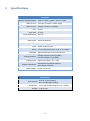
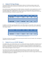
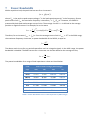
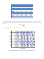
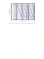
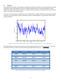
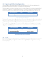
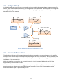
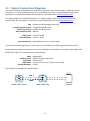
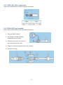
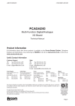
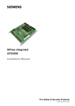
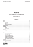
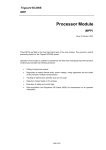
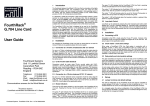
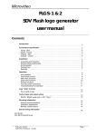
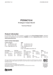
PX200 - 140 Watt Piezo Driver Manual and Specifications PiezoDrive Pty. Ltd. www.piezodrive.com 1 Contents 1 Introduction ............................................................................................................................................... 3 2 Warnings / Notes ....................................................................................................................................... 3 3 Specifications ............................................................................................................................................. 4 4 Output Voltage Range................................................................................................................................ 5 5 Output Current (200V Range) .................................................................................................................... 5 6 Output Current (100V Range) .................................................................................................................... 6 7 Power Bandwidth....................................................................................................................................... 7 8 Small Signal Bandwidth ............................................................................................................................ 10 9 Noise ........................................................................................................................................................ 11 10 Input and Offset Configuration ................................................................................................................ 12 11 Gain .......................................................................................................................................................... 12 12 Bridged Mode .......................................................................................................................................... 13 13 Overload Protection ................................................................................................................................. 13 14 Output Connection Diagram .................................................................................................................... 14 14.1 LEMO OB Cable Preparation .......................................................................................................... 15 14.2 LEMO OB Plug Assembly................................................................................................................ 15 15 Enclosure .................................................................................................................................................. 16 16 Warranty .................................................................................................................................................. 16 2 1 Introduction The PX200 is a high-power low-noise amplifier designed to drive unlimited capacitive loads from DC to 100 kHz. The output voltage range is user-selectable from ±50V to +200V which provides a high degree of application flexibility. In particular, two amplifiers can be connected in bridge-mode to provide ±200V with 280 Watts of power. The amplifier will deliver up to 4 Amps peak for sinusoidal operation, or up to 8 Amps for pulse applications The amplifier is compact, light-weight, and can be powered from any mains supply. The output connectors include LEMO 00, LEMO 0B, and 4mm Banana Jacks so many commercially available piezoelectric actuators can be directly connected. The PX200 is suited to a wide range of applications including: electro-optics, ultrasonics, vibration control, nanopositioning systems, and piezoelectric motors. 2 Warnings / Notes This device produces hazardous potentials and should be used by suitably qualified personnel under the supervision of an observer with appropriate first-aid training. Do not operate the device when there are exposed conductors. High-Voltage 3 3 Specifications Electrical Output Voltage Ranges +50V to +200V, ±100V, -50V to +150V RMS Current 1.5 Amps (3 Amps in 100V range) Peak Current 2 Amps, 4 Amps, or 8 Amps Gain 20 V/V Slew Rate 35 V/us Signal Bandwidth 390 kHz Power Bandwidth 55 kHz (200 Vp-p sine-wave) Max Power 140 W Dissipation Offset 0V to Full Range with front panel adjustment Load Stable with any load Noise 270 uV RMS (10uF Load, 0.03 Hz to 1 MHz) Overload Thermal and over-current protection Analog Outputs Voltage monitor 1/20 V/V (BNC) Current monitor 1 V/A (BNC) Analog Input Signal input (BNC, 𝑍𝑖𝑛 = 27k) Output Connectors LEMO 0B and LEMO 00 Sockets 4mm Banana Sockets Power Supply 90 Vac to 250 Vac Mechanical Environment 0 to 40C (32 to 104F) Non-condensing humidity Dimensions 212 x 304.8 x 88 mm (8.35 x 12 x 3.46 in) Weight 2 kg (4.4 lb) 4 4 Output Voltage Range The desired voltage range should be identified when ordering. The following voltage ranges can be obtained with the correct combination of installed jumpers. Note that incorrect jumper settings may damage the amplifier. The standard output voltage range is 0V to 200V. However, the amplifier can be supplied with any of the following voltage ranges by appending the order code with the voltage range code; for example, the standard configuration is PX200-V200. The voltage range jumper locations are labelled LK1 to LK8 on the PCB. Only three jumpers should be installed at any time. Voltage Range 0V to +200 0V to +150 -50 to +100 -50 to +150 -100 to +100 RMS Current 1.5 A 1.5 A 1.5 A 1.5 A 1.5 A Code -V200 -V150 -V50,100 -V50,150 -V100,100 +Supply GND -Supply LK1 LK2 LK1 LK1 LK1 LK8 LK8 LK3 LK5 LK3 LK7 LK7 LK6 LK7 LK7 Table 1. 200 Volt Range Configurations In addition to the 200V ranges described above, three 100V ranges are also possible. These ranges have the benefit of twice the peak and RMS current, which enables higher frequency operation when driving low-voltage actuators. Voltage Range 0V to +100 0V to +50 -50 to +50 RMS Current 3.0 A 3.0 A 3.0 A Code -V100 -V50 -V50,50 +Supply GND -Supply LK1 LK2 LK2 LK3 LK3 LK3 LK4 LK4 LK6 Table 2. 100 Volt Range Configurations The jumper settings can be modified by disconnecting the amplifier from mains power then removing the top panel to access the PCB board. 5 Output Current (200V Range) In the 200V ranges, the standard output current is ±2 Amps peak and 1.5 Amps RMS. This peak current is matched to the average current limit so that a sine-wave can be reproduced continuously at full current. However, for applications that require fast step changes in voltage, the amplifier can be configured in a pulse mode with 4 Amps or 8 Amps peak current limit. The maximum pulse time for each mode is listed in Table 3 and plotted against current in Figure 1. The output current range can be configured by disconnecting the amplifier from mains power then removing the top panel. The following modes can them be obtained. The amplifier can be supplied preconfigured to any current range by appending the order code with the current range code, for example, the standard configuration is PX200-C2. 5 Peak Current Code Peak Limit LK17 Overload Timer Max Pulse Time 2A 4A 8A -C2 -C4 -C8 LK11 LK12 LK13 “B” Position “B” Position ”B” Position LK16 and LK18 Out LK16 and LK18 In LK16 and LK18 In 1 ms 200 us 100 us Table 3. Current limit configuration in 200V range (Standard) 3.5 Pulse Mode 2A Limit Max Pulse Duration (ms) 3 2.5 2 1.5 1 0.5 0 0 1 2 3 4 5 Peak Current (A) 6 7 8 Figure 1. Maximum pulse time versus current 6 Output Current (100V Range) In the 100V ranges, the output current can be doubled to ±4 Amps peak and 3 Amps RMS. For applications that require fast step changes in voltage, the amplifier can also be configured in a pulse mode with 8 Amps peak. The maximum pulse time is identical to the 200V range discussed above. The output current range can be configured by disconnecting the amplifier from mains power then removing the top panel. The following modes can them be obtained. The amplifier can be supplied preconfigured to any current range by appending the order code with the current range code, for example, the 100V range and 4A current limit is PX200-V100-C4B. Peak Current Code Peak Limit LK17 Overload Timer Max Pulse Time 4A 8A -C4B -C8B LK12 LK13 “A” Position ”A” Position LK16 and LK18 Out LK16 and LK18 In 1 ms 100 us Table 4. Current limit configuration in 100V range 6 7 Power Bandwidth With a capacitive load, the peak load current for a sine-wave is 𝐼𝑝𝑘 = ±𝑉𝑝𝑝 𝜋𝐶𝑓 where 𝑉𝑝𝑝 is the peak-to-peak output voltage, 𝐶 is the load capacitance and 𝑓 is the frequency. Given a peak current limit 𝐼𝑝𝑘 , the maximum frequency is therefore 𝑓 = 𝐼𝑝𝑘 /𝑉𝑝𝑝 𝜋𝐶. However, the PX200 is protected by both peak and average current limits. The average current 𝐼𝑎𝑣+ is defined as the average positive or negative current. For example, for a sine-wave 𝐼𝑎𝑣+ = 𝐼𝑝𝑘 𝐼𝑝𝑘 1 𝜋 [−𝑐𝑜𝑠]𝜋0 = ∫ 𝐼𝑝𝑘 sin(𝜃) 𝑑𝜃 = . 2𝜋 0 2𝜋 𝜋 Therefore, for a sine-wave 𝐼𝑎𝑣+ = 𝐼𝑝𝑘 /𝜋. Since the average current limit is 𝐼𝑎𝑣+ = 0.7 in the 200V range, the maximum frequency sine-wave, or power bandwidth of the PX200, is equal to 𝑓= 0.7 , 𝑉𝑝𝑝 𝐶 The above result is true for any periodic waveform such as triangular signals. In the 100V range, the power bandwidth is doubled. The RMS current for a sine-wave can also be related to the average current, 𝐼𝑎𝑣 = √2 𝐼 . 𝜋 𝑟𝑚𝑠 The power bandwidths for a range of load capacitance values are listed below. Load Peak to Peak Voltage (200V Range) Cap. 10 nF 200 55 kHz 150 74 kHz 100 100 kHz 50 100 kHz 30 nF 55 kHz 74 kHz 100 kHz 100 kHz 100 nF 35 kHz 46 kHz 70 kHz 100 kHz 300 nF 11 kHz 15 kHz 23 kHz 46 kHz 1 uF 3.5 kHz 4.6 kHz 7.0 kHz 14 kHz 3 uF 1.1 kHz 1.5 kHz 2.3 kHz 4.6 kHz 10 uF 350 Hz 466 Hz 700 Hz 1.4 kHz 30 uF 116 Hz 155 Hz 233 Hz 466 Hz Table 5. Power Bandwidth versus Load Capacitance (200V Range) 7 Load Peak to Peak Voltage (100V Range) Cap. 10 nF 100 100 kHz 75 100 kHz 50 100 kHz 25 100 kHz 30 nF 100 kHz 100 kHz 100 kHz 100 kHz 100 nF 100 kHz 100 kHz 100 kHz 100 kHz 300 nF 46 kHz 62 kHz 93 kHz 100 kHz 1 uF 14 kHz 18 kHz 28 kHz 56 kHz 3 uF 4.6 kHz 6.2 kHz 9.3 kHz 18 kHz 10 uF 1.4 kHz 1.8 kHz 2.8 kHz 5.6 kHz 30 uF 466 Hz 622 Hz 933 Hz 1.8 kHz Table 6. Power Bandwidth versus Load Capacitance (100V Range) In the above tables, the frequencies limited by slew-rate are marked in green while the frequencies limited by signal bandwidth are marked in blue. The slew-rate is approximately 35 V/uS which implies a maximum frequency of 𝑓 𝑚𝑎𝑥 = 35 × 106 𝜋𝑉𝑝𝑝 In the following figures, the maximum frequency periodic signal in the 200V and 100V range is plotted against the peak-to-peak voltage. 220 30 uF 10 uF 3 uF 200 1 uF 300 nF 100 nF 180 Peak to Peak Voltage (V) 160 140 120 100 80 60 40 20 0 1 10 2 10 3 10 Frequency (Hz) 4 10 5 10 Figure 2. Power bandwidth versus voltage and load capacitance (200V Range) 8 110 100 uF 30 uF 10 uF 3 uF 1 uF 300 nF 100 90 Peak to Peak Voltage (V) 80 70 60 50 40 30 20 10 0 1 10 2 10 3 10 Frequency (Hz) 4 10 5 10 Figure 3. Power bandwidth versus voltage and load capacitance (100V Range) 9 Small Signal Bandwidth 3 uF 30 1 uF 300 nF 100 nF Magnitude (dB) 30 nF 20 10 nF 30 uF 10 10 uF 0 -10 -20 3 10 4 5 10 10 6 10 100 50 0 Phase (deg.) 8 -50 -100 -150 -200 -250 3 10 4 10 5 10 Frequency (Hz) 6 10 Figure 4. Small signal frequency response. Load Cap. Bandwidth 10 nF 30 nF 100 nF 300 nF 1 uF 3 uF 10 uF 30 uF 110 uF 393 kHz 431 kHz 367 kHz 208 kHz 88 kHz 30 kHz 9.3 kHz 3.7 kHz 1.3 kHz Figure 5. Small signal bandwidth versus load capacitance (-3dB) 10 9 Noise The output noise contains a low frequency component (0.03 Hz to 20 Hz) that is independent of the load capacitance; and a high frequency (20 Hz to 1 MHz) component that is inversely related to the load capacitance. Many manufacturers quote only the AC noise measured by a multimeter (20 Hz to 100 kHz) which is usually a gross underestimate. The noise is measured with an SR560 low-noise amplifier (Gain = 1000), oscilloscope, and Agilent 34461A Voltmeter. The low-frequency noise is plotted in Figure 6. The RMS value is 173 uV with a peak-to-peak voltage of 960 uV. 600 400 LF Noise (uV) 200 0 -200 -400 -600 0 5 10 15 20 t (s) 25 30 35 Figure 6. Low frequency noise from 0.03 Hz to 20 Hz. The RMS value is 173 uV, or 960 uVp-p. The high frequency noise (20 Hz to 1 MHz) is listed in the table below versus load capacitance. The total 2 2 noise from 0.03 Hz to 1 MHz is found by summing the RMS values, that is 𝜎 = √𝜎𝐿𝐹 + 𝜎𝐻𝐹 . Load Cap. Bandwidth HF Noise RMS Total Noise RMS 10 nF 30 nF 100 nF 300 nF 1 uF 3 uF 10 uF 30 uF 393 kHz 431 kHz 367 kHz 208 kHz 88 kHz 30 kHz 9.3 kHz 3.7 kHz 379 uV 382 uV 382 uV 326 uV 234 uV 214 uV 198 uV 187 uV 417 uV 419 uV 419 uV 369 uV 291 uV 275 uV 263 uV 255 uV 110 uF 1.3 kHz 183 uV 252 uV Table 7. RMS noise versus load capacitance (0.03 Hz to 1 MHz) 11 10 Input and Offset Configuration The input stage is a differential amplifier with an input impedance of 27k. The input signal ground is permitted to float by up to 0.6V before it is clamped to the system ground. The input stage is normally non-inverting; however, it can be configured as inverting by changing LK9 and LK10 to their “B” position. The default jumper position is “A” which is marked with a white bar on PCB overlay. The amplifier can be supplied with an inverting input by appending the order code with –INV. Input Configuration Non-inverting (default) Inverting Code Link Positions -INV LK9 and LK10 Both “A” LK9 and LK10 Both “B” Table 8. Input polarity configuration The input offset source is also configurable. When LK21 is in the “A” position, the offset is derived from the on-board trim-pot R15, which is adjustable from zero to full-scale. The default configuration for LK21 is in “B” position where the offset voltage is derived from the front-panel potentiometer. The standard offset voltage range is from zero volts to full-scale; however, for applications that require negative offset voltages, LK20 can be moved from the “A” to “B” position. In the “B” position, the offset range is from -100V to full-scale. Offset Configuration 0V to +200V Range (def.) -100V to +200V Range Front panel source (def.) PCB trim-pot source Code -OR2 -OS2 Link Positions LK20 “A” Position LK20 “B” Position LK21 “B” Position LK21 “A” Position Table 9. Offset voltage source configuration 11 Gain The standard voltage gain is 20 V/V. However, in the 100 Volt range, a gain of 10 may be more convenient. This can be achieved by removing LK14 and LK15. In this configuration, the voltage monitor sensitivity becomes 1/10 V/V. 12 12 Bridged Mode In bridged mode, two amplifiers are connected in series to double the output voltage range and power. To obtain ±200V at the load, the amplifiers are configured as illustrated below. Both amplifiers are configured in the ±100V range and the lower amplifier is also inverting. A ±5V signal applied to both inputs will develop ±200V at the output. ±100V ±5V Non-inverting Signal Generator 20 Voltage across load ±200V + PX200-V100,100 -20 PX200-V100,100-INV Inverting ±100V Figure 7. Bridged configuration for obtaining +/-200 V 13 Overload Protection The Shutdown indicator will illuminate during a shutdown caused by a current overload or if the amplifier overheats as a result of excessive ambient temperature, poor air-flow, or fan failure. During shutdown, the amplifier output current is limited to a few mA and may float to the high or low voltage rail if the load impedance is high or capacitive. When the amplifier is turned on, the overload protection circuit is engaged by default and will take approximately three seconds to reset. In addition to the internal shutdown triggers, the output stage of the amplifier can also be disabled by applying a positive voltage to the external shutdown connector (2V to +12V). The impedance of the external shutdown input is approximately 2.5 kΩ. 13 14 Output Connection Diagram The actuator can be connected to the amplifier by either two 4mm banana plugs, a LEMO 00 coaxial connector, or a 2-way LEMO 0B connector. The LEMO 0B connector is recommended in high power applications. Preassembled LEMO cable assemblies are available from www.PiezoDrive.com The mating plug for the LEMO 0B connector is a 2-Way straight cable plug. Ordering details and specifications are listed below. These parts can be obtained directly from www.mouser.com. Plug Crimp Terminal Version Solder Tag Version Max Conductor Size LEMO 0B 2-Way Straight Cable Plug *LEMO FGG.0B.302.CYCZ LEMO FGG.0B.302.CLAZ AWG22 Cable Collet FGG.0B.742.DN Cable Diameter 3.1mm – 4mm Strain Relief Boot GMA.0B.035.DN (3.5–3.9mm Cable) *The crimp terminal plug requires a tool, if this is not available, the solder tag plug should be used. A two conductor cable is required to connect the amplifier to a transducer. A recommended cable is the Belden 8451 cable. The specifications are listed below. Cable Conductor Size Resistance Capacitance Outside Diameter Belden 8451 AWG22 (0.64mm diameter) 53 mOhms/m 115 pF/m core–core, 220 pF/m core-shield 3.5mm The actuator wiring diagram is shown below. HV + + - GND Female Panel Socket Male Cable Plug 14 Actuator 14.1 LEMO OB Cable Preparation (Taken from LEMO 0B Series Cable Assembly Instructions) 14.2 LEMO OB Plug Assembly (Taken from LEMO 0B Series Cable Assembly Instructions) 1. Strip the cable as above 2. If the cable is shielded, fold the shield back over the cable 3. Slide the strain relief, collet nut (1) and collet (3) onto the cable. 4. Solder or crimp the conductors onto the contacts. 5. Assemble the plug, 15 15 Enclosure The PX200 enclosure has a side air intake and rear exhaust. These vents should not be obstructed. If sufficient air-flow is not available, the amplifier will enter a thermal overload state as discussed in “Overload Protection”. The PX200 amplifiers can be bolted together in a side-by-side two-channel arrangement. With the addition of rack-mount handles, this configuration can be mounted into a standard 19-inch rack. A 19-inch rackmount kit is also available for a single amplifier. 16 Warranty PiezoDrive amplifiers are guaranteed for a period of 3 months. The warranty does not cover damage due to misuse or incorrect user configuration of the amplifier. 16