1
1
Introduction
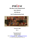
The Fourthtrack Systems FourthRack G.704 Line Card is a derivative of the highly
successful MicroMux G.704. The FourthRack G.704 Line Card has been
engineered to reduce cost and increase functionality in this expanding sector of
the market, and thus enhance Fourthtrack’s position as the market leading
provider of G.703 / G.704 Data Service Units (DSUs).
FourthRack©
G.704 Line Card
User Guide
It is designed to enable the connection of data communication systems to carrier
services, or private services, such as microwave links, that are presented as
G.703 / G.704 at 2.048Mbps. The standard model supports an X.21 DTE with 75ohm un-balanced G.703 termination. The enhanced version can support both
X.21 and V.35 DTE with 75-ohm un-balanced termination. Both versions are also
available with 120-ohm balanced termination of the G.703 network connection.
The FourthRack G.704 Line Card is designed to be used in the FourthRack
Chassis. The FourthRack chassis is a next generation rack-mount system that
supersedes the MegaChassis, with the FourthRack G.704 superseding the
MicroMux G.704 RM line card. The FourthRack Chassis has fourteen line card
slots and two power supply slots, one at each end of the chassis. The FourthRack
Chassis can be used with either a single power supply or dual power supplies for
resilience. Auto-ranging, self sensing AC power supplies, and DC power supplies
(-48VDC), are available. Please refer to the FourthRack Chassis documentation
for further information.
2
Installation
On unpacking the FourthRack G.704 Line Card you should find the unit and this
manual. If there are any questions please refer to your supplier.
2.1 Connection to a 75-ohm un-balanced G.703 / E1 network
For use on a 75-ohm un-balanced service connection should be made using the
two B.N.C. connectors on the front panel of the FourthRack G.704 Line Card.
These are labelled as "Rx" and "Tx". Your G.703 carrier service equipment may
be labelled with transmit and receive. The FourthRack G.704 LC "RX" port should
be connected to the receive side of the carrier equipment. The FourthRack G.704
"TX" port transmits carrier and this should be connected to the out-bound port of
the carrier service.
Fourthtrack Systems
Unit 11 Lowfield Green
Caversham Park
Reading – RG4 6NZ
England
Telephone: 0118-946-3061
Fax:
0118-946-3091
Web: www.fourthtrack.co.uk
Email: [email protected]
Communications answers for the World Market
©
Fourthtrack Systems
FourthRack and MicroMux are trademarks of R J Barrett
—————————————————
Fourthtrack Systems - FourthRack G.704 Rev 1.1.2 Ref: 502/634/002
2.2 G.703 75-ohm Cable Schedule
Connections should be made using 75-ohm co-axial cables with B.N.C.
connectors. The co-ax cables required are two off, 75-ohm co-ax cables, of 5mm
diameter, which must be terminated, in male BNC connectors. The maximum
cable attenuation must be 6db at 1024kHz. The attenuation characteristics should
follow the "root f" law. Cable type RG59, or 2002, or equivalent, should meet this
specification.
2.3 Connection to a 120-ohm balanced G.703 / E1 network
For use on a 120-ohm balanced service connection should be made using the
RJ45 connector on the front panel of the 120-ohm version of the FourthRack
G.704 LC. This is labelled as RJ45. The pin out for the RJ-45 is as defined for
ONP/CTR-12 and is given in the specification section.
2.4 Status Indicators
There are five LED status indicators on the front panel of the FourthRack G.704
Line Card. Reading from the top of the front panel these are labelled P, N, C, T
and L.
The green ‘P’ LED indicates that the FourthRack G.704 LC is receiving power
from the FourthRack back plane. The FourthRack Chassis and the FourthRack
G.704 support ‘hot-swap’. The FourthRack G.704 has a built-in power-up control
system. The ‘P’ LED will illuminate a few seconds after the FourthRack G.704
Line Card is inserted into the rack and the back plane connection has been made.
The green ‘N’ LED indicates that the FourthRack G.704 Line Card is receiving
correctly encoded data from the line interface equipment.
The amber ‘C’ LED indicates that the FourthRack G.704 Line Card is set to clock
master mode. See set-up section for setting the clock master mode.
The amber ‘T’ LED will illuminate when the use of the Terminal Timing option is
selected. See set-up section for setting the terminal timing mode.
The amber ‘L’ LED will illuminate when the loop-back condition is selected. (See
below for Loop Back operation)
2.5 Loop back Control
Loop Back can be selected by pressing the small recessed push button switch
between the T and the L indicators labelled LB. Loop back mode is cancelled by
pressing the LB switch again. If the Loop Back mode is not deselected using the
switch the Line Card will automatically revert to its normal operating mode after 2
minutes.
3
Installation
3.1 Connecting to DTE
Connection to the DTE is made using the 15 way "D" socket. Versions of the
FourthRack G.704 Line Card are available that support X21 or X21 and V35. The
pinout is given in the specification section
3.2 Clock master / clock slave settings
When using a FourthRack G.704 Line Card system in conjunction with a
MicroMux G.703/4, or when using a FourthRack G.704 LC at either end of a
2048kbit/s circuit in clear channel operation, one of the units should be set to
clock master. The Fourthtrack Systems recommendation is to set the system that
is closest to the network core to clock master and the unit that is closest to the
subscriber / customer site to clock slave.
3.3 Data polarity and clock polarity settings
The data transmitted and received on the G.703 side of the FourthRack G.704
could have originated on another piece of equipment. It is not uncommon for the
data to be inverted by G.703 terminating equipment. The FourthRack G.704 has
the option to invert or not invert the data transmitted and received on the G.703
port. See the set-up section for the default setting and changing the data polarity.
In some cases, when using an X.21 interface, the data received from the DTE
may be mis-aligned with the X.21 timing signal, and this can cause errors. This
situation can usually be overcome by changing the polarity of the clock used to
clock in the received data, with respect to the X.21 timing signal. The FourthRack
G.704 has the option to change the polarity of the clock used to clock in received
data. See the set-up section for the default setting and changing the clock polarity.
4
Set-up
4.1 Jumper functions and default settings
The start-up configuration of the FourthRack G.704 Line Card is controlled by
jumpers grouped in link fields. The primary link field is identified as LK11. It is
located toward the rear of the Line Card adjacent to the back plane connector.
In a managed system the start-up configuration of the FourthRack G.704 Line
Card is read from NV-RAM or up-loaded from the FourthRack Management Card,
as defined by the management settings.
Configuration Jumper Table
Ident
Note (1)
Open
Note (2)
Note (3)
Closed
21-22
(by R18)
Read/Write - Managed use
only
Read Only - for Managed &
Unmanaged use (default)
19-20
(by R51)
TS0 Disabled (default)
TS0 Enabled
17-18
(by R50)
LIU
LIU CRC4 Enabled
15-16
(by R48)
DTE RXD Clock Inverted
(default)
DTE RXD Clock Not
Inverted
13-14
(by R47)
DTE RXD clocked from
recovered G.703 timing
(default)
DTE RXD clocked from DTE
TTC. (see note(1) on timing
skew below)
11-12
(by R46)
AIS disable
AIS enable (default)
9-10
(by R45)
G.703 Data Inverted
(default- see note (2) below)
G.703 Data Not Inverted
CRC4
Disabled
1-2
Data Rate / Timeslot allocation".
(Default is 2048 Kbps - clear channel)
G.703 Clock Slave (default)
(by R41)
For full details on the management functionality refer to the User Guide supplied
with the rack.
G.703 Clock Master (see
MTTC for source)
Ident
Note (1) - used to cancel skew in loop timing due to buffers and cable propagation
delays. Recovered G.703 clock is presented on DTE CLK to be looped back at
the far end on DTE TTC.
Note (2) - the normal or default operation is with the data inverted. (NB Fitting the
link inverts the data from this 'normal' state. This is consistent with the 'DINV ON'
state displayed by the managed unit user interface and the switch being in the
'ON' position for standalone units.)
Links 3-4, 5-6 and 7-8 are used to set the data rates manually. Please refer to the
table below.
Data rate
Timeslot allocation
3-4
5-6
7-8
(1)
1 → 31
Open
Open
Open
1920(1) Kbps
1 → 15 & 17 → 31
Closed
Open
Open
1024(2) Kbps
1 → 16
Open
Closed
Open
1024(2) Kbps
1 → 15 & 17
Closed
Closed
Open
512(2) Kbps
1→8
Open
Open
Closed
256(2) Kbps
1→4
Closed
Open
Closed
128(2) Kbps
1→2
Open
Closed
Closed
2048(2&3) Kbps
0 → 31
Closed
Closed
Closed
Kbps
120 Ohm Balanced
Rx
1
G.703
Tx
V.35
Ident
V.35
X.21
LK8
V
X
LK15
V
X
LK13
V
X
LK16
V
X
LK14
5
X.21
V
X
Specifications
RJ45 Pin
Function
1&2
Rx pair from network
3
Shield reference point
4&5
Transmit pair to network
5.4 Shield reference point
Note that the Receive Shield reference point is taken to ground via a link field.
Fitting the jumper LK17 connects Receive Shield to ground.
5.5 DTE Connector
Chassis
1
TXD A
2
nc
3
RXD A
4
IND A
5
CLK A
6
TTC A
7
Ground
8
9
TXD B
10
nc
11
RXD B
12
IND B
13
CLK B
14
TTC B
15
nc
5.1 On Board Master Clock
4.2 Data rate / timeslot allocation
1984
75 Ohm Unbalanced
Configuration parameters selected using LK11 may be overridden via FourthRack
management. Management selected configuration options are maintained in nonvolatile memory when the card is removed or when power is lost. If set to ‘read
only’ the FourthRack G.704 will power-up with the configuration defined by its LK4
settings. If set to ‘read / write’ the FourthRack G.703 will power-up with the
configuration defined by management and saved in its non-volatile memory.
The enhanced version of the FourthRack G.704 Line Card can support both X.21
and V.35 DTE. The DTE interface function is selected using a link field identified
as ‘V X’. It is located toward the front of the Line Card adjacent to the DTE
connector. Links in the ‘V X’ link field are three position. One or other option must
be selected for the DTE interface to function. DTE interface status is readable by
management, however, as the links in this field control signal termination and
drivers they cannot be overridden by management.
See below:
3-4
(by R42)
Two versions of the FourthRack G.704 Line Cards are available
4.4 Interface selection on dual function X.21 / V.35 version
7-8
(by R44)
"4.2
5.3 Network Connectors
4.3 Management capability
The FourthRack is available with management. The management is supported by
using a different power supply module that includes the management function.
The FourthRack may be used with either one or two of the management
enhanced power supplies providing resilience for both power and the
management function.
(default)
5-6
(by R43)
Gapped clocking is used to accommodate this data rate. Clock speed
is 2048 Kbps.
Continuous clock
Clear channel (unstructured G.703) operation
Fourthtrack Systems - FourthRack G.704 Rev 1.1.2 Ref: 502/634/002
Operating Frequency: 2.048 MHz + 50 PPM @ 25 deg. C
15 way D type Socket
5.2 Network Interface Signals Specification
The Network Interface conforms to CCITT specification G.703 and ETSI Open
Network Provision for digital unstructured leased line (D2048U).
5.6 Environmental
Transmit.
The FourthRack G.704 Line Card is designed to operate under the following
conditions.
Output Pulse amplitude
Return Loss
2.37 V into 75R + 10%
3.00 V into 120R + 10 %
Min 8 dB - Max 14 dB
Receive.
Sensitivity Below (0dB = 2.4 V)
Loss of Signal Threshold
Return Loss
Allowable consecutive Zeros
before LOS
- 10dB
0.3V
18 dB
190 bits.
Ambient temperature:
Relative humidity:
Atmospheric pressure:
Power requirement:
5 to 45 degrees Celsius.
10 to 90 percent (non-condensing).
86kPa to 106kPa.
Powered via the FourthRack chassis