1
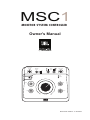
MSC1
MONITOR SYSTEM CONTROLLER
Owner's Manual
MSC1
by
HARMAN
MONITOR SYSTEM CONTROLLER
HEADPHONE
VOLUME
A
SPEAKER
SELECT
B
A
INPUT
SELECT
A/B
INPUT TRIM
C
RMC
B
POWER
CLIP
SIGNAL
MSC1
RMC
EQ
SUB
MUTE
MONITOR SYSTEM CONTROLLER
-∞
MAX
VOLUME
MSC1
Document Version: 11.23.2010
Table of Contents
Section 1: Important Safety Instructions . . . . . . . . . . . . . . . . . . . 3
Section 2: Introduction . . . . . . . . . . . . . . . . . . . . . . . . . . . . . . . 4
Section 3: Quick Start. . . . . . . . . . . . . . . . . . . . . . . . . . . . . . . . . 6
Section 4: Setting Up Your MSC1 . . . . . . . . . . . . . . . . . . . . . . . 7
Power Connections . . . . . . . . . . . . . . . . . . . . . . . . . . 7
Audio Connections . . . . . . . . . . . . . . . . . . . . . . . . . . 7
Getting Sound . . . . . . . . . . . . . . . . . . . . . . . . . . . . . . 8
MSC1 System Example . . . . . . . . . . . . . . . . . . . . . . 9
Section 5: Features and Operation . . . . . . . . . . . . . . . . . . . . . 10
MSC1 front panel controls . . . . . . . . . . . . . . . . . . . . 10
MSC1 rear panel connectors . . . . . . . . . . . . . . . . . 14
Section 6: Installing MSC1 Control Center Software
- Windows Operating System . . . . . . . . . . . . . . . . . 16
To Uninstall the MSC1 Control Center Software . . 18
Launching the MSC1 Control Center Software
- Windows Operating System . . . . . . . . . . . . . . . . . 19
Section 7: Installing MSC1 Control Center Software
- Macintosh Operating System. . . . . . . . . . . . . . . . . 20
To Uninstall the MSC1 Control Center Software . . . 22
Launching the MSC1 Control Center Software
- Macintosh Operating System. . . . . . . . . . . . . . . . . 23
Section 8: Reference . . . . . . . . . . . . . . . . . . . . . . . . . . . . . . . . 24
Section 9: Troubleshooting . . . . . . . . . . . . . . . . . . . . . . . . . . . . 26
Section 10: Specifications . . . . . . . . . . . . . . . . . . . . . . . . . . . . 30
Section 11: JBL Service Contact Information . . . . . . . . . . . . . . 32
Section 12: Product Warranty Information . . . . . . . . . . . . . . . . 33
2
Section 1: Important Safety Instructions
1. Read these instructions.
2. Keep these instructions.
3. Heed all warnings.
4. Follow all instructions.
5. Do not use this apparatus near water.
6. Clean only with dry cloth.
7. Do not block any ventilation openings. Install in accordance with
manufacturer’s instructions.
8. Do not install near any heat sources such as radiators, heat registers, stoves
or other apparatus that produce heat.
9. Protect the power cord from being walked on or pinched particularly at plugs,
convenience receptacle and the point where the power cord connects
to the apparatus.
10. Only use attachments/accessories specified by the manufacturer.
11. Unplug this apparatus during lightning storms or when unused for long
periods of time.
12. Refer all servicing to qualified service personnel. Servicing is required when
the apparatus has been damaged in any way, including: power-supply cord
or plug is damaged, liquid has been spilled or objects have fallen into the
apparatus, the apparatus has been exposed to rain or moisture, does not
operate normally, or has been dropped.
13. The appliance coupler of the power supply cord is used as the ultimate
disconnect device from the mains. The appliance coupler shall remain readily
operable.
14. The apparatus shall be connected to mains socket outlet with a protective
earthing connection.
15. POWER ON/OFF SWITCH: The power switch DOES NOT interrupt connection
to the mains. To disconnect the product from the mains, remove the power
cord connector from the power input on the rear panel of the product.
16. Caution: This product is used to control loudspeaker volume. Very loud
playback volume can damage hearing. Never adjust speaker volume to
produce an output level that is audibly painful.
WARNING: To reduce the risk of fire or electrical shock, do not expose the apparatus to rain or
moisture. The apparatus shall not be exposed to dripping or splashing and no objects filled with
liquids, such as vases, shall be placed on the apparatus. As with any electronic product, use care
not to spill liquids into any part of the system. Liquids can cause a failure and/or a fire hazard.
CAUTION! TO REDUCE THE RISK OF ELECTRONIC SHOCK - DO NOT REMOVE
COVER. NO USER SERVICEABLE PARTS INSIDE. REFER SERVICING TO QUALIFIED
PERSONNEL. DO NOT EXPOSE THIS APPARATUS TO RAIN
OR MOISTURE.
3
Section 2: Introduction
Congratulations on your purchase of the JBL MSC1 Monitor System Controller,
a unique product that combines the essential "Monitor Strip" functions found in
large mixing consoles with JBL’s highly acclaimed RMCTM Room Mode Correction
technology, that allows any connected speaker system to be automatically tuned
to your room. The end result is a calibrated reference environment in which your
speakers work in harmony with your room to take the guesswork out of mixing. As
the hub of your system, the MSC1 provides these powerful capabilities:
Mixing Console "Monitor Strip" Functions
• Monitor using two sets of stereo speakers.
• Monitor with and without a connected subwoofer* – The MSC1 automatically
balances the subwoofer and gives you a choice of cross-over settings for proper
integration of your subwoofer into your speaker system.
• Connect up to three 2-channel signal sources, and select the source to be
monitored.
• Send a headphone feed to a performer, or use headphones in the control room
to monitor program material.
• Tailor the frequency response of your speakers using flexible high and low
frequency EQ.*
JBL RMC Room Mode Correction
With the supplied MSC1 Control Center Software and MSC1 calibration microphone,
the MSC1 tunes the low frequency response of the speaker system* to compensate
for inaccuracies measured at the listening position caused by room modes (standing
waves) and the speakers proximity to walls, and the work surface.
Supplied MSC1 Control Center Software
Install the supplied MSC1 Control Center software on your computer to perform
RMC Calibration, adjust equalizer settings, speaker level and delay, and fine tune
a connected subwoofer.*
*Note: the processing functions of the MSC1 Room Mode Correction, EQ, subwoofer
settings, speaker level and delay are available on "A" SPEAKER OUTPUTS. Flat,
unprocessed signal is routed to "B" SPEAKER OUTPUTS. The subwoofer output is muted
when "B" SPEAKER OUTPUTS are selected.
We know that very few people read owner’s manuals from cover to cover, so we’ve
organized this one to make it easy to find the information you need.
4
Section 2: Introduction
The section Setting Up Your MSC1 will get you up and running in a matter of minutes.
This is followed by a 1 page Quick Start section guide that provides a very basic
set of instructions for use of all the MSC1 features. The Quick Start is followed
by a section that describes every feature and function of the MSC1 in detail. Next
are directions for installing the supplied MSC1 Control Center software, which
allows advanced functions such as calibration of the RMC Room Mode Correction
system, adjustment of equalization, subwoofer settings and fine speaker alignment
including delay and level trim controls. Finally, we’ve included troubleshooting tips
and specifications at the end of this manual, along with service contact and warranty
information.
TM
Note: Throughout this manual, important tips and cautions will be presented like this.
Registration
Please take a moment to register your MSC1. Registration can be accomplished
on-line by going to www.jblpro.com/MSC1. Click on "Register your product" and
complete the on-line form. Thank you.
5
Section 3: Quick Start
1. Install the MSC1 Control Center Software following the procedure on
pages 16.
2. Connect the MSC1 power supply to an available wall outlet and then
connect the MSC1 to your computer using the supplied USB cable.
3. Launch The MSC1 Control Center Via the Desktop Icon.
4. To power the MSC1 on or off, press the MSC1’s Power button or click
on the Power Button image in the Software.
5. To change subwoofer level, crossover frequency or polarity settings,
click the SUB button in the software or press the MSC1 front panel SUB
control. Make adjustments using the on-screen Sub controls. To view
Subwoofer settings at any time, click on the SUB GRAPH Tab.
6. To apply high frequency and low frequency monitor EQ, click the EQ
button in the software or press the MSC1 front panel EQ control. Make
adjustments using the on screen EQ controls. To view EQ settings at
any time, click on the EQ Graph tab.
7. To enable MUTE click on the MUTE button in the software or press the
front panel MSC1 MUTE control.
8. To activate Room Mode Correction (RMC) settings, click the RMC
button in the software or press the front panel MSC1 RMC control.
9. To perform RMC Calibration, click RMC Menu, RMC Calibration, and
follow the on-screen instructions.
10. To change the level of an individual speaker, click RMC Menu, RMC
Alignment, and use your mouse to adjust the level slider, to the left of
each speaker image. Note: Speakers levels are automatically adjusted
during the RMC Calibration procedure.
11. To apply delay to an individual speaker click RMC Menu, RMC
Alignment, and use your mouse to move the Delay level slider, to the
right of each speaker image.
6
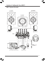
Section 4: Setting Up Your MSC1
Power Connections
Connect the MSC1 power adaptor to the POWER Connector on the
rear of the MSC1. Plug the power adaptor into a suitable available
power source. To minimize the potential for "ground-related" noise, we
recommend connecting MSC1 to the same power source as the audio
equipment and computers connected to the MSC1.
12VDC 500mA
Audio Connections
The MSC1 Monitor System Controller is equipped with balanced 6.5mm
(1/4 inch) TRS (Tip-Ring-Sleeve) output connectors for the connection of two
stereo speaker systems (labeled "A" and "B"), plus a dedicated balanced 6.5mm
(1/4 inch) TRS connector for the connection of a subwoofer to system A.
In addition, three pairs of input connectors are provided: two pairs of balanced
6.5mm (1/4 inch) TRS connectors, labeled A and B, and one unbalanced pair
of PHONO (RCA) connectors, labeled C, allowing the MSC1 to be used with
a wide variety of professional computer audio interfaces, soundcards, mixing
consoles and audio production equipment, as well as consumer audio products
with unbalanced outputs such as personal music players, receivers and audio
visual equipment. Finally, a stereo 6.5mm (1/4 inch) stereo headphone output
with dedicated front-panel volume control allows you to send a headphone feed
to a performer or monitor audio using headphones in the control room.
. Note: Two additional rear-panel stereo 3.5mm (1/8 inch) audio connectors, labeled
"RMC MIC IN" and "RMC MIC OUT," are used only during RMC calibration.
See page 14 in this manual for more information.
Note: To avoid audible noise, make audio connections with speakers and MSC1
powered off.
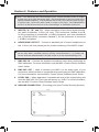
The following illustration shows various suggested MSC1 audio interconnections.
The use of balanced cabling is recommended when connecting the MSC1 to
equipment with balanced inputs and outputs as it ensures the best possible
signal-to-noise performance. Additionally, use of unbalanced cable in systems
with balanced inputs and outputs can reduce system gain by as much as 6 dB.
Confirm the settings of controls on connected speakers and subwoofer:
• Speaker and subwoofer volume controls should be set to maximum setting.
• If the Subwoofer includes a crossover control, it should be set to the highest
available frequency.
• Speaker tone controls may be used, but we recommend these are bypassed
prior to RMC calibration and restored according to taste, after RMC calibration
(See MSC1 Control Center Software User’s Guide).
7
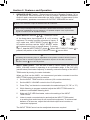
Section 4: Setting Up Your MSC1
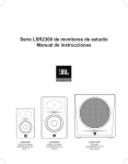
Getting Sound
Make all audio connections with
the power to all devices off. Once
all connections are made, set the
MSC1 front panel VOLUME control
to minimum (fully counterclockwise),
then power on all connected devices,
and power on the MSC1 itself, by
pressing the MSC1 front-panel
POWER switch. Finally, power on the
speaker system.
HEADPHONE
VOLUME
A
SPEAKER
SELECT
1
2
A/B
INPUT
SELECT
B
A
INPUT TRIM
C
B
RMC
B
POWER
CLIP
SIGNAL
RMC
EQ
SUB
MUTE
-∞
Minimum
Control
Not Illuminated
MAX
VOLUME
Next, make sure the front panel
MUTE button is not illuminated and then use the front panel SPEAKER SELECT
switch to choose the desired speaker system ("A" or "B") you wish to hear. Use the
front panel INPUT SELECT switches 1 and 2 to choose the input signal ("A", "B",
or "C") you wish to monitor.
Note: If INPUT SELECT switch 2 is depressed (set to the C position), the MSC1 will
always be monitoring Input C, regardless of the position of INPUT SELECT 1 , even if
nothing is physically connected to Input C.
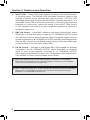
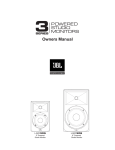
Finally, send audio signal from the
device connected to the selected
input and slowly advance the
MSC1 VOLUME control until you
achieve a suitable listening level.
If necessary, adjust the MSC1 INPUT
TRIM control for maximum signal
strength. It is OK if the MSC1 CLIP
LED illuminates occasionally.
HEADPHONE
VOLUME
A
SPEAKER
SELECT
B
A
1
2
INPUT
SELECT
A/B
INPUT TRIM
C
B
RMC
B
POWER
Occasional
Illumination
OK
CLIP
SIGNAL
RMC
EQ
SUB
MUTE
-∞
Control
Not Illuminated
MAX
VOLUME
Note: Although any audio source may be connected to any input "A", "B", or "C", we
recommend connecting professional equipment with high level +4 dBu outputs (mixing
consoles, professional audio interfaces and playback equipment) to input connectors
A or B, and consumer equipment with low-level -10 dBV outputs (receivers, personal
music players, electronic keyboards and rhythm machines) to the C input connectors.
For more information, and details about setting the INPUT TRIM control, refer to the
"Front Panel" and "Rear Panel" sections on pages 9 - 14 of this manual, and to the
"Troubleshooting" section on page 20.
8
Section 4: Setting Up Your MSC1
MSC1 System Example
"A" Speaker
Right Channel
"A" Speaker
Left Channel
"A" Speaker
Subwoofer
115
115
"B" Speaker
Right Channel
"B" Speaker
Left Channel
MSC1
Headphones
RMC
Calibration Mic
(included)
MP3
Player
Digital audio workstation
with computer audio interface
Mixing console
9
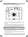
Section 5: Features and Operation
Front Panel Controls, Indicators, and Functions:
4
5
HEADPHONE
VOLUME
6
A
SPEAKER
SELECT
B
A
1
7
2
INPUT
SELECT
A/B
INPUT TRIM
C
RMC
B
1
POWER
CLIP
2
8
SIGNAL
9
RMC
EQ
SUB
10
MUTE
-∞
MAX
VOLUME
11
3
12
1. POWER LED – This LED (Light Emitting Diode) flashes twice when the MSC1
is first connected to a power source and remains illuminated when the MSC1 is
powered ON.
2. POWER SWITCH - When the MSC1 is connected to an AC power source, press
this button to power-on the MSC1 (The front panel buttons will illuminate in a pattern).
To power off the MSC1, press the power button again. Once power down begins,
the sound is muted while a different light pattern is displayed. Do not disconnect the
power adaptor until all MSC1 front panel indicators are no longer illuminated.
Note: The power switch and all MSC1 features are disabled for 4 seconds immediately
following connection of MSC1 to a power source.
3. MSC1 VOLUME – Sets the output level for the selected input signal (see #6),
from -∞ (full attenuation) to MAX (0 dB, or no attenuation). Note that this control
does NOT affect headphone output level (see #4).
4. HEADPHONE VOLUME Control – A dedicated volume control for connected
headphones. Other than this, the only MSC1 control that effects the headphone
signal is MUTE control (see #12).
10
Section 5: Features and Operation
5. SPEAKER SELECT switch – Determines which set of Speaker Outputs ("A" or
"B") are active. When the button is in the up position, speakers connected to
Output A and a connected subwoofer are active. When it is depressed (in the
down position), speakers connected to B OUTPUT SPEAKER are active.
Note: The subwoofer output is disabled when B is selected
Note: The processing functions of the MSC1 (Room Mode Correction, EQ, and
subwoofer capabilities) are only applied to "A" Speaker Outputs. Flat, unprocessed
signal is routed to the "B" Speaker Outputs.
6. INPUT SELECT switches 1 & 2 – Determine which
1
2
A
A/B
of the three stereo input signals (A, B, or C) is being
INPUT
SELECT
C
B
B
monitored. To monitor sources connected to inputs A
or B, make sure INPUT SELECT switch 2 is in the
UP position and then use the INPUT SELECT switch
1 to choose Input A (up) or Input B (down). To monitor
Input C, depress INPUT SELECT switch 2 . When INPUT SELECT Switch 2 is
pressed, the position of the INPUT SELECT Switch 1 has no effect.
Note: If the INPUT SELECT Switch 2 is depressed (set to the C position), the MSC1
will always be monitoring Input C, regardless of the position of INPUT SELECT Switch
1 . If you wish to monitor equipment connected to Inputs A or B make sure INPUT
SELECT Switch 2 is in the UP position.
7. INPUT TRIM Control – Can be used to add or reduce system gain once the
MSC1 VOLUME control is operating in a comfortable range. If the CLIP LED
(see #8 below) illuminates frequently or steadily, reduce the setting of the INPUT
TRIM control by turning it counter-clockwise.
When you first use the MSC1, we recommend you take a moment to set the
INPUT TRIM control using this procedure.
1. Set the INPUT TRIM control to minimum (full counter-clockwise)
2. Set the MSC1 VOLUME control to the 12:00 position.
3. Press "Play" on the device connected to the selected input ("A", "B", or "C")
4. While listening to program material, adjust the INPUT TRIM control to achieve a comfortable listening level.
5.
6.
If the red CLIP LED illuminates, reduce the setting of the INPUT
TRIM control.
Listen to each connected device and adjust the INPUT TRIM control
to a setting that works best for all connected equipment. To achieve best
balance of all sources, adjust the individual output level controls on connected equipment.
The INPUT TRIM Control can be readjusted whenever required.
11
Section 5: Features and Operation
8. INPUT LEDs – These LEDs (Light Emitting Diodes) provide visual indication
of incoming signal. The SIGNAL LED illuminates whenever signal of any
strength is present at the selected input (see #6 above). The CLIP LED
illuminates when signal is within 3 dB of the MSC1 maximum level output. It is
acceptable for this LED to illuminate occasionally. If the CLIP LED illuminates
frequently or continuously, reduce the setting of the INPUT TRIM Control
or use available level controls on the connected equipment to reduce the
equipment output level.
9. RMC ON Control – Once RMC calibration has been performed this button
allows you to quickly and easily compare the "A" SPEAKER OUTPUT signal
with and without Room Mode Correction. When illuminated, signal is sent to
speakers connected to "B" SPEAKER OUTPUTS with RMC processing applied.
(See the MSC1 Control Center Software User's Guide.) Press this button again
(no illumination) to hear the signal without RMC.
10. EQ ON Control – Activates or deactivates MSC1 EQ available for speakers
connected to the "A" SPEAKER OUTPUT. When illuminated, an equalized
signal is sent to the speakers connected to "A" SPEAKER OUTPUT.
Press again (no illumination) to listen to the "A" speakers without equalization.
(See the MSC1 Control Center Software User's Guide.)
Note: EQ is applied to the Left and Right speakers connected to "A" SPEAKER
OUTPUTS only. Equalization does not affect Speakers connected to "B" SPEAKER
OUTPUTS nor the Subwoofer or headphones.
Note: If enabled, the RMC and / or EQ Controls flash repeatedly instead of illuminating
steadily when "B" SPEAKER OUTPUTS are selected because EQ processing is
available on "A" SPEAKER OUTPUTS only.
12
Section 5: Features and Operation
11. SUB ON control – If a subwoofer is connected to the SUB Output "A", and
the "A" speakers are being monitored, this control allows you to quickly
and easily listen to "A" speakers with and without a subwoofer. When the
subwoofer is included in the system, Bass Management Crossover filters
are applied that route low frequency signals below the crossover frequency
to the subwoofer and signals above the crossover frequency to the Left
and Right speakers. When the SUB control is illuminated, the subwoofer
is heard. When the control is not illuminated, the subwoofer is muted and
the Left and Right speakers play a full range signal. Subwoofer Level and
Bass Management crossover are set using MSC1 Control Center software.
Three Bass Management crossover frequencies are provided and the MSC1
ships with an 80 Hz Bass Management crossover selected and subwoofer
gain set to 0 dB (no additional boost or attenuation). (See the MSC1 Control
Center Software User's Guide.)
Note: If your subwoofer has a crossover frequency control, the control should be set to
the highest available frequency.
Note: The SUB control will flash repeatedly instead of illuminating steadily when
Speaker Output B is selected because a connected subwoofer can be heard only when
Speaker Output A is selected
12. MUTE control – When illuminated, mutes all output signal from the MSC1,
including the headphone output.
13
Section 5: Features and Operation
Reference: Rear Panel
3
1
2
5
4
8
9
7
6
1. POWER CONNECTOR – Connect the supplied 12VDC 500mA power supply
here. Note that when the MSC1 is first plugged in, the front panel POWER LED
will flash twice, after which the MSC1 enters stand by mode. When in stand by
mode, no indicators are illuminated and audio output is not available.
2. USB CONNECTOR – Universal Serial Bus connector for computer
connection when using the provided MSC1 Control Center software.
3. SPEAKER OUTPUTS (A, B) – Two pairs of balanced 6.5mm (1/4 inch) TRS
connectors labeled A and B for connection of two stereo speaker systems.
Note: The processing functions of the MSC1 (Room Mode Correction, EQ, and
subwoofer capabilities) are only applied to the "A" SPEAKER OUTPUTS. Flat,
unprocessed signal is routed to "B" SPEAKER OUTPUTS.
4. SUB A OUTPUT – A dedicated balanced 6.5 mm (1/4 inch) TRS connector
for the addition of a subwoofer to System A.
14
Section 5: Features and Operation
Note: If the Subwoofer has Left and Right inputs, connect the MSC1 SUB "A" Output
to either the Left or Right Subwoofer input. Set the Subwoofer crossover control to the
highest available frequency. If the Subwoofer has a LFE (Low-Frequency Effects) input
or a direct input, connect the MSC1 SUB "A" output to this input. The SUBWOOFER
OUTPUT is derived from the sum of the Left and Right "A" SPEAKER OUTPUTS.
5. INPUTS ("A", "B", and "C") – Allow connection of up to three signal sources:
two pairs of balanced 6.5mm (1/4 inch) TRS connectors, labeled A and B,
for the connection of professional (+4 dBu) equipment, plus one unbalanced
pair of PHONO (RCA) connectors, labeled C, for the connection of consumer
(-10 dBV) equipment.
6. HEADPHONE OUTPUT – Connect a standard pair of stereo headphones to
this 6.5mm (1/4 inch) stereo jack for private monitoring of the MSC1 output.
Note: For private monitoring of the MSC1 signal over headphones with all speakers off,
turn the main MSC1 VOLUME control to its fully counterclockwise ("-∞") position and
use the dedicated HEADPHONE VOLUME control to set the desired listening level.
7. RMC MIC IN – Connect the supplied microphone here when performing an
RMC calibration. For more information, see the MSC1 Control Center Software
User's Guide.
8. RMC MIC OUT – Used to connect your MSC1 to the audio input of your
computer’s audio interface or soundcard when performing an RMC calibration.
For more information, see the MSC1 Control Center Software User's Guide.
9. LEVEL PAD – When depressed, increases the level of the signal being sent
from the RMC MIC OUT jack (see #8 above) by 8 dB. For more information,
see the MSC1 Control Center Software User's Guide.
10. GROUND CONNECTION – Grounding point (See Trouble Shooting Section)
Rear
Ground Screw
Front
15
Section 6: Installing the MSC1 Control Center Software
Windows Operating System
Minimum System Requirements
Hard Drive: 200 MB available space
RAM: 1 GB minimum
CPU: Pentium(4) 1.6 GHZ or better (Duo core recommended)
Netbook and ATOM processor not supported
Operating System: Windows XP (SP2), Vista, Windows7 32-bit / 64-bit
Audio: Accessible analog audio IN/OUT connectors of an internal
soundcard or optional external audio interface, Directx9 compatible.
USB Port
Minimum Screen Resolution:1024 x 768.
Uses MS .NET 2.0
Uses Directx 9.0c
Uses Adobe ® Flash 9 or later
Uses Adobe Acrobat ® Reader 7 or later
Microsoft, Adobe are registered trademarks of their respective owners.
Harman Professional claims no ownership or goodwill in the use of these trademarks.
Note: Use on a Macintosh Computer requires Macintosh version
MSC1 Control Center Software and Macintosh Operating System.
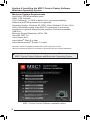
MSC1 Control Center Software Installation Menu
16
Section 6: Installing the MSC1 Control Center Software
Windows Operating System
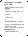
INSTALLATION - WINDOWS
From CD-ROM:
1. Insert the supplied CD-ROM in an available CD-ROM drive.
The installation application should launch automatically.
2. In the event that the installation doesn’t auto-launch, from the Start
Menu, click RUN
3. Click BROWSE
4. Locate the drive containing the MSC1 Control Center Software CD-ROM.
5. Click on the file named MSC1_Application_Installer.EXE and the
MSC1CC Installation Application will open.
If the Installer will not open after attempting to launch it:
A. From the Start Menu Click RUN.
B. Click BROWSE.
C. Locate the drive containing the MSC1 Control Center Software CD-ROM.
D. Navigate to the MSC1 Installer Folder.
F. When the installation is complete, attempt to launch the MSC1
Installation software again.
6. There are several software components, listed in the MSC1CC
Software Installation Screen, required to successfully run the MSC1
Control Center.
The MSC1 Installation Software checks your system and determines
the current availability of each component. A checkmark appears in
the check box adjacent to a given component’s launch button if it is
determined the component is already installed. Therefore a component
that has a check mark in its check box does not require installation.
7. If you attempt to load an application previously installed on your
computer, the instructions will ask you if you would like to repair,
uninstall, or cancel the installation. At this point you should cancel the
installation of that particular application.
8. Going down the list, for each component without a checkmark, press
the corresponding launch button to begin installation.
To install from a downloaded .ZIP file:
1. Copy the file to the desktop
2. Extract the contents using an archive application.
NOTE: To maintain the correct file structure, you must use the "Extract"
function of the archive application. Proceed to step #5 above.
17
Section 6: Installing the MSC1 Control Center Software
Windows Operating System
9. During the MSC1 Control Center Software installation, a launch icon is
placed on the desk top.
10. The Directx 9.0c installation will ask you to choose a directory for the
installation. Select any location on your C: Drive. For example, create a
directory called C:\directx-9c on your hard drive and select this location
for the install.
11. The ATMEL FLIP installation will ask you if you want to restart your
machine. If you select NO, then as you exit the MSC1CC Installation
you will be reminded that you must restart your computer before using
the MSC1CC Software.
12. After you restart your computer, you can launch the MSC1 Control Center.
To Uninstall the MSC1 Control Center:
Launch Control Panel >Add or Remove Programs. From the “Currently
Installed Programs” List, Find and highlight “MSC1 Control Center.”
Then Click “Remove.”
18
Note: From time to time, JBL will issue software updates that
enhance MSC1 Control Center functionality. If your computer is
connected to the internet, software updates can be downloaded
at www.jblproservice.com; otherwise you can obtain the update by
contacting JBL Professional Customer Service at (800) 8JBLPRO
(800-852-5776), Monday-Friday, 8am-5pm P.S.T.
Section 6: Installing the MSC1 Control Center Software
Windows Operating System
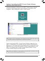
Following installation, a shortcut to the MSC1 Control Center Software
is placed on your desktop and in your computer’s Start Menu under
Programs > JBL Professional > MSC1 Control Center.
Start Menu Launch Icon
Start Menu Launch Icon
Your MSC1 must be connected to your computer with the supplied USB cable and
powered on before launching the MSC1 Control Center Software.
Prior to launching the MSC1 Control Center Software, make sure your
MSC1 is connected to your computer with the supplied USB cable and
powered on. Then double-click on the desktop icon (or single-click on the
Start menu icon) to launch the software. See the Features section in the
MSC1 CC Software User’s Guide for details about all MSC1 Control
Center Software display and menu options.
To protect your speakers, it is good practice to complete audio connections with the
MSC1 and all connected equipment powered off.
19
Section 7: Installing the MSC1 Control Center Software
Mac Operating System
Minimum System Requirements
Hard Drive: 200 MB available
RAM: 1 GB minimum
CPU: Power PC / Intel 2.0 GHZ or better (Duo core recommended)
Operating System: Tiger 10.4.1.1 through Snow Leopard 10.6,
Power PC/Intel.
Audio: Accessible analog audio IN/OUT connectors of an internal
soundcard or optional external audio interface.
USB port.
Minimum Screen Resolution: 1024 x 768.
Uses: Adobe ® Flash 9 or later, Adobe ® Acrobat Reader 9 or later.
Apple, Adobe, Intel are registered trademarks of their respective owners.
Harman Professional claims no ownership or goodwill in the use of these trademarks.
Note: Use on an Intel Macintosh Computer requires Macintosh version
MSC1 Control Center Software and Macintosh Operating System.
MSC1 Control Center Software Installation Menu
20
Section 7: Installing the MSC1 Control Center Software
Mac Operating System
INSTALLATION - MACINTOSH OS
From CD-ROM:
1. Insert the included MSC1 Control Center CD-ROM in an available CDROM drive.
2. Double Click the CD icon to BROWSE.
FOR INTEL MACINTOSH Computers
3. Locate the file named MSC1CCSW_MAC_INTEL_(version number)__
(release date).mpkg and drag it to your desktop. Proceed to step #4
below
FOR POWER PC MACINTOSH Computers
3. Locate the file named MSC1CCSW_MAC_PPC_(version number)__
(release date).mpkg and drag it to your desktop.
Proceed to step #4 below
4. Once copied double-Click on the file to open the MSC1CC Installation
Application. Proceed to step 5.
5. Each stage of the installation is completed by pressing the “Continue”
button.
6. Read the Introduction and then Continue.
7. Review the "Read me" file for important information.
8. Select a destination drive for the MSC1 Control Center, Continue.
9. Click the CUSTOMIZE button at the bottom of the window. After
clicking CUSTOMIZE, all available software components for
installation are listed on this screen. All listed components are
required. Unless a more recent version of a component is already
installed, ensure that the check box is checked for all components.
If you are installing an updated version of the MSC1 Control Center,
you must UNINSTALL the previous version before proceeding with the
current installation.
10. Press “Install” to begin installation. During the MSC1 Control Center
Software Installation, a MSC1 Control Center icon is placed in the
“Applications/MSC1” folder.
11. After pressing “Close”, launch the MSC1 Control Center program by
clicking the icon in the “Applications/MSC1” folder.
21
Section 7: Installing the MSC1 Control Center Software
Mac Operating System
To install from downloaded .ZIP file:
1. Download the correct file for INTEL or POWER PC Macintosh
2. Copy the file to to the desktop.
3. Extract the contents using an archive application.
NOTE: To maintain the correct file structure, you must use the "Extract"
function of the archive application. Proceed to step #4 above.
To Uninstall the MSC1 Control Center:
Locate the MSC1 folder in the Applications folder and move it to
the trash.
22
Note: From time to time, JBL will issue software updates that
enhance MSC1 Control Center functionality. If your computer is
connected to the internet, software updates can be downloaded
at www.jblproservice.com; otherwise you can obtain the update by
contacting JBL Professional Customer Service at (800) 8JBLPRO
(800-852-5776), Monday-Friday, 8am-5pm P.S.T.
Section 7: Installing the MSC1 Control Center Software
Mac Operating System
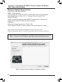
Following installation, Double-click the MSC1 icon placed in the
“Applications/MSC1” Folder.
Desktop
Your MSC1 must be connected to your computer with the supplied USB cable and
powered on before launching the MSC1 Control Center Software.
Prior to launching the MSC1 Control Center Software, make sure your
MSC1 is connected to your computer with the supplied USB cable and
powered on. Then double-click on the MSC1 icon to launch the
software. See the Features section in the MSC1 CC Software User’s
Guide for details about all MSC1 Control Center Software display and
menu options.
To protect your speakers, it is good practice to complete audio connections with the
MSC1 and all connected equipment powered off.
23
Section 8: Reference
JBL RMC™ Room Mode Correction:
About RMC
The biggest challenge for anyone producing audio is creating a mix that sounds
great on all playback systems. If you think of a monitoring system as a kind of "lens"
through which you hear sound, the object is to have the lens be crystal-clear and
transparent so that it imparts no coloration whatsoever to the signal being played
back. However, every loudspeaker system, no matter how well designed, interacts
with the room in which it is installed. Lack of correct acoustic treatment (or, worse
yet, lack of any treatment at all) can result in anomalies such as low-frequency
"standing waves"—the aural equivalent to the lens being "smeared." Trying to
create a mix in such an environment can be as frustrating and difficult as trying to
paint a masterpiece while blindfolded.
JBL’s exclusive RMC Room Mode Correction technology is designed to solve the
problem. It uses the power of your computer to analyze the acoustic conditions of your
room RMC then compensates for low frequency inaccuracies in the listening space
by having the MSC1 precisely insert filters so that signals arrive at the mix position
with the intended frequency response. By making precise corrections, RMC allows
you to create reliable mixes that translate to any environment. Space limitations in
the work environment may prevent ideal positioning of the Left and Right speakers
and subwoofer. The MSC1 allows you to precisely trim the level of each connected
speaker, and apply delay to compensate for differences in placement relative to the
mix position, ensuring balanced mixes regardless of speaker placement.
Performing an RMC Calibration
The supplied MSC1 Control Center software, MSC1 Calibration Microphone, and
accessory cables are required to perform an RMC calibration. Refer to the supplied
MSC1 Control Center Software Users Guide for full instructions.
Subwoofer Bass Management Crossover
Adding a subwoofer to your system will extend the frequency response of
the main speakers. "Bass management" is a term that refers to the practice of
removing bass signals from the Left and Right speakers and sending them to the
subwoofer. Because of the physiology of the human ear, low frequencies are largely
non-directional: given an adequate listening distance, we can’t easily tell where
bass signals are coming from. Thus, it makes little or no difference to the listening
experience whether the bass component of a sound comes from the Left or Right
channel speaker or from a dedicated subwoofer which is better equipped, and better
positioned in the room, to reproduce low frequencies than even a full range monitor.
Beyond the fact that a subwoofer is designed for the optimal reproduction of low
frequencies, bass management can also be used to solve acoustic problems in a
room: having all the low frequency signals come from a single source can eliminate
low frequency phase cancellation that occurs when the same low frequency signal
is reproduced by multiple speakers. The MSC1 SUB Control allows you to easily
enable or disable the Subwoofer and Bass Management system.
24
Section 8: Reference
In addition to allowing connection of a subwoofer, the MSC1 includes sophisticated
Bass Management Crossover with a choice of three crossover frequencies, to precisely
integrate the subwoofer into your system. When the SUB Control is Illuminated, the
SUB output is enabled and the MSC1 Bass Management Crossover is engaged. When
the control is not illuminated, the subwoofer output is muted and the Left and Right
speakers return to full-range operation. Three crossover settings are provided and can
be set using the MSC1 Control Center software: 60 Hz, 80 Hz and 120 Hz. Also, using
the software, the subwoofer level can be increased or decreased by 10 dB. Finally,
during RMC calibration, the sub is automatically balanced to the speaker system.
Equalization
Equalization can be applied to speakers connected to the Left and Right "A"
SPEAKER OUTPUTS to tailor response to preference, or acoustic conditions
in the room.
The MSC1 offers two bands of equalization (high and low frequency
shelving type), with up to 3 dB of attenuation or boost in each band. Using the
supplied MSC1 Control Center software, the corner frequency for each band is
adjustable from 34 Hz to 1.1 kHz (LF) and 2.5 kHz and 17 kHz (HF).
To turn equalization on, press the EQ button so that it is illuminated. Equalization
settings are accomplished, and presets can be created using the supplied
MSC1 Control Center software.
Delay and Level Trim
Left and Right Speakers and a subwoofer connected to the "A" SPEAKER OUTPUTS
can be level-matched and independently delayed to compensate for differences in
placement relative to the listening position. These adjustments can be made using
a computer and supplied MSC1 Control Center software.
Left and Right speaker levels can be independently attenuated up to 12 dB in .25
dB increments. The subwoofer level can be adjusted +/- 10 dB in .25 dB increments,
allowing it to be finely balanced in the system.
Left and Right speakers and the subwoofer can also be independently delayed
which can be useful if, out of necessity, the left and right speakers differ in distance
from the listening position. The application of delay to the closer of the two speakers
will restore strongest possible stereo image by allowing sound from both speakers
to arrive at the ears at precisely the same time, regardless of physical positioning.
Delaying the subwoofer, or the Left and Right speakers relative to the subwoofer,
can enhance the low frequency performance of the system by virtually aligning
the subwoofer with the main speakers. Delay units are expressed in values of
distance, from 0 feet (0 cm) to a distance of 3.75 ft. (114 cm) in 1 inch (2.54 cm)
increments. The subwoofer can be delayed from 0 ft. (0 cm) to 3.17 ft (96.6 cm).
For example, applying a delay value of 1 ft. (30.45 cm) to a speaker will cause the
audio from that speaker to sound as if it originates 1 foot farther away relative to
the other speakers.
25
Section 9: Troubleshooting
No sound
• Confirm that the power cable is connected and that the MSC1 is powered on
(POWER LED is illuminated).
• Confirm that a signal source is connected and producing sound and the INPUT
SELECT switches are set correctly. (Note that if the INPUT SELECT switch
2 is depressed [set to the C position], you will always be monitoring Input C,
regardless of the position of the INPUT SELECT 1 , even if no signal is physically
connected to INPUT C.)
• Confirm connected speaker system is powered on and the SPEAKER SELECT
switch is set correctly.
• Confirm that the MUTE button is not illuminated.
• Make sure the MSC1 VOLUME control is not set to the fully counter clockwise
("-∞") position.
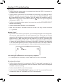
System "hum"
• If you hear "hum" noise in your system, try connecting all signal source equipment,
the computer and speakers to the same electrical power outlet. (Do not connect
equipment with total power requirements that exceed the capabilities the provided
power source). If after doing this you still hear hum, you can try "grounding" the
MSC1 to an available ground source. To do this, use a Philips head screw driver
to loosen the ground screw on the bottom of the MSC1. Attach an insulated wire
to the screw and tighten the screw. Connect the other end of the wire to different
ground points of your audio system to find and achieve the best performance.
Rear
Ground Screw
Left and Right Speakers lack low frequency response
• If no subwoofer is connected, confirm SUB Control is not illuminated.
No subwoofer signal
• Confirm that a subwoofer is connected to Sub "A" output and is powered on, it’s
Front
volume control is set to maximum,
and it’s crossover control is set to the highest
available crossover setting.
• Confirm that the SUB control is illuminated.
• Confirm that the SPEAKER SELECT switch is set to "A". (A connected Subwoofer
is heard only when "A" SPEAKER OUTPUTS are selected)
26
Section 9: Troubleshooting
Subwoofer is not loud enough
• Use MSC1 Control Center software to adjust subwoofer level and Bass
Management Crossover settings.
• If your system incorporates different models or brands of speakers and subwoofer
it may be necessary to adjust the subwoofer level or Left and Right Speaker
levels to balance the Sub in the system.
No difference in sound when the RMC control is activated or deactivated
• Using the supplied MSC1 Control Center software, confirm that RMC calibration
has been performed.
• Confirm that the SPEAKER SELECT switch is set to "A". (RMC processing is
available when the "A" SPEAKER OUTPUTS are selected.)
No difference in sound when the EQ control is activated or deactivated
• Using the supplied MSC1 Control Center software, confirm that an EQ setting
has been made. (See MSC Control Center Software User’s Guide.)
• Confirm that the SPEAKER SELECT switch is set to "A". (EQ affects only signal
sent to "A" SPEAKER OUTPUTS.)
RMC, EQ, and SUB buttons flash when pressed instead of illuminating steadily
• The SPEAKER SELECT switch is set to "B". (Processed signal (RMC
and/or EQ) and subwoofer signal is heard only when routing signal to
"A" SPEAKER OUTPUTS. Only flat, unprocessed signal is routed to
"B" SPEAKER OUTPUTS.)
The CLIP LED is illuminated consistently and/or distorted sound is heard
• Output level of the equipment connected to the selected input is too high.
To remedy this do one of the following:
1. Reduce the setting of the INPUT TRIM control.
2. Reduce the output level of the connected equipment using available output
level control on the equipment.
3. If the CLIP LED illuminates with input "C" selected, disconnect the equipment
from Input C and reconnect the equipment to Input "A" or "B", which are
designed to accept greater signal levels.
If the above measures do not correct the problem, please contact JBL Professional
Customer Service (see page 26 in this manual for more information).
27
Section 9: Troubleshooting
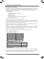
Restoring Factory Settings
Some MSC1 features are set using MSC1 Control Center software. The Factory
Reset procedure restores the features to original default settings. Using the Factory
Reset procedure, the following features, available for speakers connected to "A"
SPEAKER OUTPUTS, are reset:
• Equalization
• Sub Bass Management Crossover
• Subwoofer Level
• Subwoofer Polarity
• Individual level trim for Left and Right Speakers
• Speaker Delay settings
To perform Factory Reset, follow this procedure:
Press and hold the MSC1 front panel RMC control for 6 seconds, until the MUTE and
RMC controls begin to flash. Continue to press the RMC control, and simultaneously
press the MUTE control. Then release both buttons.
Completion of the process is confirmed when LEDs on the MSC1 illuminate in a
pattern for 15 seconds, and the power LED illuminates.
If after performing Factory Reset, the MSC1 is interfaced to a computer and MSC1
Control Center Software is launched, the software will offer the option of returning
the MSC1 to the settings last stored in software.
Note: The Factory Reset procedure erases all user settings, in the MSC1.
MSC1 Factory Settings
"A" Left and Right Speaker
Feature
LF EQ Boost/ Cut
HF EQ Boost/Cut
LF EQ Frequency
HF EQ Frequency
Level Trim
Factory Setting
0 dB
0 dB
580 Hz
7.75 kHz
0 dB
Delay
0 inches / mm
Subwoofer Output
Sub Level
0 dB
Bass Management Crossover
80 Hz
Sub Polarity
0 degrees
Delay
0 Inches / mm
Firmware Update
From time to time, JBL may release a firmware update to correct a problem or
enhance the feature set. If a firmware update is released, the update and installation
instructions will be posted on the JBL website at www.jblproservice.com.
28
Section 10: Specifications
S/N, Dynamic Range:
110 dB typical, A-weighted, 20 Hz - 20 kHz
Frequency Response:
+0/-0.5dB, 20 Hz - 20 kHz
THD+N:
< 0.04% A/D/A, 20 Hz - 20 kH
A/D Converters:
24 Bit 64-times Oversampling Delta-Sigma
D/A Converters:
24 Bit, 8-times Oversampling Delta-Sigma
Internal Processing:
48 Bit, 48 kHz
Maximum Input Level:
+24 dBu, 6.5mm (1/4-inch) TRS Inputs;
+12 dBu, PHONO (RCA) Inputs
Maximum Output Before Clipping:
+17 dBu, 0.025% THD
Input Impedance:
20k ohms 6.5mm (1/4 inch) TRS Inputs;
10k ohms PHONO (RCA) Inputs
Output Impedance:
100 ohms
Power Requirements:
12 VDC, 0.5A
Dimensions (w x d x h):
198 x 165 x 83 mm (7.8 x 6.5 x 3.25 in)
Shipping Weight Including Accessories: 1.96 kg (4.3 lbs.)
"A" Left and Right Speaker
Feature
LF EQ Boost/ Cut:
HF EQ Boost/Cut:
LF EQ Frequency:
HF EQ Frequency:
Level Trim:
Available Delay:
Subwoofer "A" Output
Feature
Sub Level:
Bass Management Crossover:
Sub Polarity:
Available Delay:
RMC Parameters Filters
Left and Right Speakers:
Subwoofer:
Range
+/- 3 dB in 0.25 dB increments
+/- 3 dB in 0.25 dB increments
34 Hz to 1.1 Hz
2.5 kHz to 17 kHz
+0/-12 dB in 0.25 dB increments
0 to 114 cm (3 feet 9 inches) in 2.54 cm
(1 inch) increments
Range
+/-10 dB in 0.25 dB increments
60 Hz, 80 Hz, 120 Hz
0 degrees, 180 degrees
96.5 cm (3 feet 2 inches) in 2.54 cm (1 inch) increments
5 filters. Range: 32 Hz to 350 Hz. Gain: +0/-18 dB
2 filters. Range: 28 Hz to 150 Hz. Gain: +0/-18 dB
MSC1 Control Center Software Requirements:
Use on a Macintosh Computer requires Macintosh version MSC1 Control Center Software and
Macintosh Operating System.
Windows OS Specs:
Hard Drive: 200 MB available space • RAM: 1 GB minimum • CPU: Pentium (4) 1.6 GHZ or
better ( Core™ 2 Duo recommended) • Operating System: Windows XP or Vista, 32-bit and
64-bit • Internal Soundcard or External Audio Interface, compatible with Directx 9 • Minimum
Screen Resolution: 1024 x 768
Macintosh OS Specs:
Hard Drive: 200 MB available • RAM: 1 GB minimum • CPU: Power PC / Intel 2.6 GHZ or
better (Duo core recommended) • Operating System: Tiger 10.4.11; Leopard 10.5 or later:
Snow Leopard 10.6 Or later • Internal Soundcard or External Audio Interface • Minimum
Screen Resolution: 1024 x 768
29
Section 10: Specifications
Electromagnetic Compatibility:
This unit conforms to the Product Specifications noted on the Declaration of Conformity.
Operation is subject to the following two conditions: 1) this device may not cause harmful
interference, and 2) this device must accept any interference received, including interference
that may cause undesired operation.
Operation of this unit within significant electromagnetic fields should be avoided.
Use only shielded interconnecting cables.
Regulatory Information:
An example of this equipment has been tested and found to comply with the following
European and international Standards for Electromagnetic Compatibility and Electrical Safety:
Conforms to:
• FCC Part 15, Subpart B, Class B
• EN55022 Class B
• EN55024
30
• EN61000-3-2
• EN61000-3-3
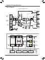
Section 10: Specifications
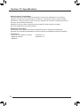
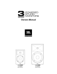
Block Diagram
Controller Signal Flow
Output
Amplifiers
L/R
L
Speaker Select
A/B
Input Select
Select A/B or C
R
A
Limiter
A/B
L
L/R
L/R
B
L
A/D
L/R
C
DSP D/A
Input B
L/R
R
Filter
parameters
-36dB
R
B
L
L
L/R
Mute
Balanced
Out B
R
R
0dB
A/D
L/R
Input C
R
INPUT TRIM
L
Phono
(RCA)
Inputs
12dBu Max
L/R
R
A
S
+6dB
Balanced 6.5mm
( -inch)
TRS Inputs
24dBu Max
L
Balanced
Out A
L/R
L/R
Input A
Headphones
Mute
LEDs
Enable
L
Balanced 6.5mm
( -inch)
TRS Inputs
24dBu Max
-∞ dB
Clip
LED
Signal
LED
L/R
0 dB
Headphone
Volume
Sub
Micro-Controller
-∞ dB
Balanced
Out Sub A
VOLUME
R
RMC
EQ
Power
Mic Out
Sub
Mic In
12V
Phantom
Power
USB
Mute
Front Panel Controls with LEDs
+8dB
0dB
LEVEL PAD
DSP Signal Flow
RMC Filters
nd
Left Channel
Five 2 order
Adaptive Filters
Low Freq
Shelving
Filter
Five 2ndorder
Adaptive Filters
High Freq
Shelving
Filter
+3dB
+3dB
-3dB
-3dB
Fl
Right Channel
Crossover Filters
EQ Filters
Low Freq
Shelving
Filter
Fh
High Freq
Shelving
Filter
Left Speaker A
3rd order HP
Left Mixer In
1st, 2nd
order
filters
3rd order LP
Subwoofer A
Sub Level
+10dB / -10dB
Right Mixer In
3rd order HP
Right Speaker A
VOLUME
-∞ dB to 0dB
RMC
Function
Software
EQ Controls
Software
Sub Controls
Speaker
Configuration
Function
VOLUME
Micro-controller
31
Section 11: JBL Service Contact Information
by
HARMAN
Mailing Address:
JBL Professional
8500 Balboa Blvd.
Northridge, CA 91329
Shipping Address:
JBL Professional Customer Service
JBL Professional
8500 Balboa Boulevard, Dock #15
Northridge, CA 91329 USA
(Do not return product to this address without first obtaining prior
authorization from JBL)
On The World Wide Web:
www.jblpro.com/LSR
Product Registration:
Register your product online at www.jblpro.com/registration
Customer Service:
Monday through Friday
8:00am - 5:00pm
Pacific Coast Time in the U.S.A.
(800) 8JBLPRO (800.852.5776)
www.jblproservice.com
Professional Contacts, Outside the USA:
Contact the JBL Professional Distributor in your area. A complete list
of JBL Professional international distributors is provided at our U.S.A.
website: www.jblpro.com
En Dehors des Etats-Unis:
Contacter votre Distributeur JBL Professional. Une liste complète de
nos distributeurs internationaux est disponible sur le site web www.jblpro.com
International:
Wenden Sie sich an Ihre örtliche JBL Professional Vertretung. Eine
vollständige Liste der internationalen JBLVertretungen finden
Sie auf userem Website unter www.jblpro.com
Fuera de los Estados Unidos:
Comuníquese con el distribuidor de JBL Profesional de su zona.
En nuestro sitio web, www.jblpro.com, encontrará una lista completa
de distribuidores JBL.
32
Section 12: Product Warranty Information
The JBL Limited Warranty on the MSC1 Monitor System Controller remains
in effect for one year from the date of the first consumer purchase.
Who Is Protected By This Warranty?
Your JBL Warranty protects the original owner and all subsequent owners so long as:
A.) Your JBL product has been purchased in the Continental United States, Hawaii
or Alaska. (This Warranty does not apply to JBL products purchased elsewhere
except for purchases by military outlets. Other purchasers should contact the local
JBL distributor for warranty information.); and B.) The original dated bill of sale is
presented whenever warranty service is required.
What Does The JBL Warranty Cover?
Except as specified below, your JBL Warranty covers all defects in material and
workmanship. The following are not covered: Damage caused by accident, misuse,
abuse, product modification or neglect; damage occurring during shipment; damage
resulting from failure to follow instructions contained in your Owners Manual;
damage resulting from the performance of repairs by someone not authorized by
JBL; claims based upon any misrepresentations by the seller; any JBL product on
which the serial number has been defaced, modified or removed.
Who Pays For What?
JBL will pay all labor and material expenses for all repairs covered by this warranty.
Please be sure to save the original shipping cartons because a charge will be made
if replacement cartons are requested. Payment of shipping charges is discussed in
the next section of this warranty.
How To Obtain Warranty Performance
If your JBL product ever needs service, write or telephone us at JBL Incorporated
(Attn: Customer Service Department), 8500 Balboa Boulevard, PO. Box 2200,
Northridge, California 91329 (818/893-8411). We may direct you to an authorized
JBL Service Agency or ask you to send your unit to the factory for repair. Either
way, you’ll need to present the original bill of sale to establish the date of purchase.
Please do not ship your JBL product to the factory without prior authorization.
If transportation of your JBL product presents any unusual difficulties,
please advise us and we may make special arrangements with you. Otherwise,
you are responsible for transporting your product for repair or arranging for its
transportation and for payment of any initial shipping charges. However, we will pay
the return shipping charges if repairs are covered by the warranty.
33
Section 12: Product Warranty Information
Limitation of Implied Warranties
ALL
IMPLIED
WARRANTIES,
INCLUDING
WARRANTIES
OF
|MERCHANTABILITY AND FITNESS FOR PARTICULAR PURPOSE, ARE
LIMITED IN DURATION TO THE LENGTH OF THIS WARRANTY.
EXCLUSION OF CERTAIN DAMAGES
JBL’S LIABILITY IS LIMITED TO THE REPAIR OR REPLACEMENT, AT OUR
OPTION, OF ANY DEFECTIVE PRODUCT AND SHALL NOT INCLUDE
INCIDENTAL OR CONSEQUENTIAL DAMAGES OF ANY KIND. SOME STATES
DO NOT ALLOW LIMITATIONS ON HOW LONG AN IMPLIED WARRANTY
LASTS AND/OR DO NOT ALLOW THE EXCLUSION OF INCIDENTAL OR
CONSEQUENTIAL DAMAGES, SO THE ABOVE LIMITATIONS AND EXCLUSIONS
MAY NOT APPLY TO YOU. THIS WARRANTY GIVES YOU SPECIFIC LEGAL
RIGHTS, AND YOU MAY ALSO HAVE OTHER RIGHTS, WHICH VARY, FROM
STATE TO STATE.
34
by
HARMAN
JBL Professional
8500 Balboa Boulevard
Northridge, CA 91329 USA
www.jblpro.com
Part Number: 444307-001
Rev 11.22.10