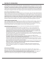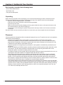
1
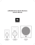
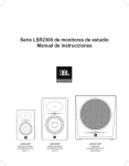
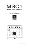
Owners Manual
LSR305
5" Powered
Studio Monitor
LSR308
8" Powered
Studio Monitor
2
Section 1: Important Safety Instructions
1. Read these instructions.
Explanation of Graphic Symbols
2. Keep these instructions.
The exclaimation point within an equilateral
triangle is intended to alert the users to the
presence of important operating and maintenance (servicing) instructions in the literature
accompanying the product.
3. Heed all warnings.
4. Follow all instructions.
5. Do not use this apparatus near water.
6. Clean only with dry cloth.
7. Do not block any ventilation openings. Install in
accordance with manufacturer’s instructions.
8. Do not install near any heat sources such as
radiators, heat registers, stoves or other apparatus
that produce heat.
9. Do not defeat the safety purpose of the grounding type
plug. A polarized plug has two blades with one wider
than the other. A grounding type plug with two blades
and a third grounding prong. The wide blade or the third
prong is provided for your safety. If the provided plug
does not fit into your outlet, consult an electrician for
replacement of the obsolete outlet.
The lightning flash with the arrowhead
symbol, within an equilateral triangle, is to
alert the user to the presence of insulated
“dangerous voltage” within the products enclosure that may be of sufficient magnatude
to constitute a risk of electric shock
to humans.
CAUTION: TO REDUCE THE RISK
OF ELECTRONIC SHOCK - DO NOT
REMOVE COVER. NO USER
SERVICEABLE PARTS INSIDE. REFER
SERVICING TO QUALIFIED PERSONNEL.
DO NOT EXPOSE THIS APPARATUS TO
RAIN OR MOISTURE.
10. Protect the power cord from being walked on or pinched
particularly at plugs, convenience recepticle and the
point where the power cord connects to the apparatus.
Any changes or modifications not expressly approved
by the party responsible for compliance could void the
user's authority to operate the equipment.
11. Only use attachments/accessories specified by the
manufacturer.
This equipment has been tested and found to comply
with the limits for a class B digital device, pursuant to
part 15 of the FCC Rules.These limits are designed to
provide reasonable protection against harmful interference in a residential installation. This equipment
generates, uses and can radiate radio frequency energy
and, if not installed and used in accordance with the
instructions, may cause harmful interference to radio
communications. However, there is no guarantee that
interference will not occur in a particular installation. If
this equipment does cause harmful interference to radio
or television reception, which can be determined by
turning the equipment off and on, the user is encouraged
to try to correct the interference by one or more of the
following measures:
12. Unplug this apparatus during lightning storms or when
unused for long periods of time.
13. Refer all servicing to qualified service personnel.
Servicing is required when the apparatus has been
damaged in any way, including: power-supply cord or
plug is damaged, liquid has been spilled or objects
have fallen into the apparatus, the apparatus has been
exposed to rain or moisture, does not operate normally,
or has been dropped.
14. The appliance coupler of the power supply cord is used
as the ultimate disconnect device from the mains. The
appliance coupler shall remain readily operable.
15. The apparatus shall be connected to mains socket outlet
with a protective earthing connection.
WARNING:
To reduce the risk of fire or electrical shock, do not expose
• the
apparatus to rain or moisture.
•
The apparatus shall not be exposed to dripping or
splashing and no objects filled with liquids, such as vases,
shall be placed on the apparatus. As with any electronic
product, use care not to spill liquids into any part of the
system. Liquids can cause a failure and/or a fire hazard.
• Reorient or relocate the receiving antenna.
Increase the separation between the equipment
• and
receiver.
Connect the equipment into an outlet on a circuit
• different
from that to which the receiver is connected.
Consult the dealer or an experienced radio/ TV
• technician
for help.
3
Contents
Important Safety Instructions......................................................................................... 3
Introduction ................................................................................................................... 5
Setting Up Your System................................................................................................. 6
What's Included?..................................................................................................... 6
Unpacking............................................................................................................... 6
Placement............................................................................................................... 6
Audio Connections.................................................................................................. 7
Power Connections................................................................................................. 7
Making Sound......................................................................................................... 7
4
LSR305 and LSR308 Powered Studio Monitors
Front and Rear Views............................................................................................. 8
Input Panel.............................................................................................................. 9
Audio Connections.................................................................................................. 9
Systems Connections ................................................................................................. 10
Appendix – Trouble Shooting.......................................................................................11
Appendix - Specifications............................................................................................ 12
JBL Service Contact Information................................................................................. 13
Product Warranty Information ..................................................................................... 14
Section 2: Introduction
Congratulations on your purchase of JBL Professional 3 Series Studio Monitors. These studio monitors meet JBL’s
high standards for accuracy and long-term reliability in demanding professional applications. All 3 Series models
incorporate JBL Professional transducer and network technologies to provide accurate frequency response,
exceptional low frequency extension and high SPL capability. JBL LSR Linear Spatial Reference design ensures
greater accuracy at the mix position in acoustically varied work spaces and production environments. Additionally,
each speaker is equipped to interface with a range of signal sources including high-output professional equipment.
JBL LSR Linear Spatial Reference Design
Because listening environments vary, JBL designed the 3 Series system using LSR Linear Spatial Reference
design criteria that improve accuracy at the listening position in a broad range of rooms. The key to accuracy is
ensuring not just the on-axis sound, but also the reflected sound reaching the mix position is neutral. While most
manufacturers take only a single on-axis measurement of the speaker’s performance, Linear Spatial Reference
design criteria requires 72 measurements, 360 degrees around the speaker, yielding more than 1,200 times more
data. This data is used in the design of critical system components, enabling JBL to engineer complete systems
that deliver smooth off-axis response. The result: clear accurate sound at the listening position in any room.
3-Series Image Control Wave Guide
JBL’s revolutionary Image Control Waveguide gives the LSR305 and LSR308 remarkable imaging, a wide soundstage, and a solid “phantom center.” Subtle details can be heard, even in a dense mix. As an added benefit,
incorporating this wave guide, 3-Series models give you a broad “sweet-spot” in your work space, so you don’t
have to be seated directly in front of the speakers to hear accurate, natural and open sound.
3 Series Models include a range of features to meet the needs of demanding audio production applications.
LSE305 and LSR308 Models include:
• Low frequency magnetically-shielded transducers, equipped with 1.5" voice coils and robust motor
structures to provide excellent low frequency performance. By reducing thermal-related effects, the 3
Series Studio Monitors sound the same at low, medium and high levels. The woofers are magnetically
shielded to prevent interference with magnetically sensitive displays and equipment. The woofer’s selfrepairing dust dome is resistant to dents caused by fingers or external objects.
• JBL’s Patented Slip Stream™ low frequency port design that works in concert with the woofer to produce
deep bass response at all playback levels. The double-flared shape of the port is precisely engineered for
greater low-frequency extension and reduced turbulence.
• Bi-amplified Design with individual power amplifiers for the Low Frequency and High Frequency
Transducers. The design utilizes efficient high-output Class D integrated power amplifiers to provide high
SPL (Sound Pressure Level) for demanding production applications.
• Soft dome magnetically-shielded high-frequency transducers with optimally damped materials to improve
transient response and minimize distortion. By reducing distortion in the lower operating range, where the
ear is most sensitive, these transducers reduce ear fatigue.
• Balanced XLR and 1/4" connectors, a dented level attenuator to allow interface to a broad range of signal
sources. The +4 dB / -10 dB input sensitivity switch allows connection of the speakers to high-output
professional equipment without danger of input overload.
• High Frequency and Low Frequency Trim controls in the LSR308 and LSR305 allow adjustment of
frequency response to preference, or to compensate for acoustically reflective or absorptive listening
environments.
JBL Professional Reliability
Prior to becoming a production-ready design, each 3 Series model is subjected to JBL’s tough 100 hour
power test, in which the speaker is required to play continually at full output for 100 hours without failure. This
demanding test ensures your 3 Series speakers will deliver years of reliable performance.
To get the most out of your JBL 3 Series Studio Monitors, please review this owner’s manual and keep it on
hand for future reference. Also, please register your new speakers at www.jblpro.com/registration.
5
Section 3: Setting Up Your System
Each speaker includes the following items:
• One 3 Series Studio Monitor
• One Power Cord
• Four peel-off rubber pads
Unpacking
When removing a speaker from its packaging, we recommend the following procedure, which will prevent
damage of the high frequency transducer located near the top of the cabinet on the front of the speaker:
• Remove the outer shipping carton, if one exists.
• Place the inner carton on the floor with the top facing upwards.
• Open the top of the box.
• Without removing the internal packaging end-cap, gently rotate the carton so the open end rests on the
floor and the bottom of the carton is facing you.
• Gently lift the carton allowing the speaker and protective end-cap to slide out of the carton and remain
on the floor.
Save the cartons and use the above procedure in reverse when you want to repack the units for shipment.
Placement
3 Series speakers are designed to deliver exceptional imaging in any room, To get the most out of your speakers,
follow these recommendations
• Attach the four supplied pads to each speaker to protect the finish on the bottom of the speaker.
• Position each speaker in a vertical orientation with the tweeter on the top. Vertical orientation eliminates
phase shift and cancellation of frequency response that occurs when the distance of the woofer to the ear
is different from the distance of the tweeter to the ear.
• Angle the speakers so the high-frequency transducer in each speaker is aimed directly towards the ear of
the listener.
• Ideally, the LSR308 and LSR305 speakers should be placed on suitable speaker stands, rather than on the
work surface. This will reduce resonance and deterioration of low frequency performance that occurs
through the speaker’s mechanical coupling with the work surface.
• For optimum imaging, the left speaker and the right speaker should be placed symmetrically in the room, so
each speaker is the same distance from adjacent walls and reflective surfaces.
• The speakers should be placed so the position of the listener and the two speakers form an equilateral
triangle. Adjusting the distance between the speakers will affect the quality of bass heard at the listening position. You can experiment with speaker placement to find the placement that produces the preferred
bass response, imaging and when listening to stereo material, produces a strong “phantom” center in which
vocals and some instruments seem to originate from a point between speakers.
• The listening distance can be determined according to your preference, the acoustics of your room and the
maximum SPL (Sound Pressure Level) you want to hear at the listening position. You can find the speaker’s
maximum SPL at 1 Meter in the Specifications Section at the end of this manual. Each doubling of listening
distance will reduce the SPL at the listening position by 6 dB in an acoustically absorptive room, but only
3 or 4 dB in an acoustically reflective room.
6
D
30º
D
D
30º
Place the speakers so the distance "D" between
the speakers is the same as the distance to the
listening position.
Audio Connections
The 3 Series Speakers are equipped with balanced XLR and 6 mm (¼") TRS inputs for connection to professional
computer audio interfaces, mixing consoles and audio production equipment as well as unbalanced consumer
audio products including personal music players, consumer audio receivers and audio visual equipment. Connect
professional equipment with balanced outputs to the XLR or 6 mm (¼") TRS input of the speaker using balanced
signal cables.
3-Series speakers are equipped with an INPUT SENSITIVITY SWITCH. The switch is set to the -10dB setting
when it ships from our factory. This setting will be best for many applications. However, you can set the switch to
the +4 dB setting:
• When connecting 3 Series speakers to professional equipment with +4 dB nominal output level, set
the INPUT SENSITIVITY SWITCH to the +4 dB setting. To determine the nominal output level of the
connected equipment, consult the documentation supplied with the connected equipment.
• If you notice the sound is distorted, or you find it is too loud, set this switch to the +4 dB setting.
Power Connections
The 3 Series speakers incorporate a universal power supply allowing these to be used domestically and
internationally. The ground terminal of the IEC plug is required by wiring codes and regulations and must always
be connected to the electrical installation safety ground.
Making Sound
After connections are made, reduce the output level of the audio source (mixing console, computer recording
system, or preamp) to minimum. Set the 3 Series POWER SWITCH to the “ON position.” After a short delay the
POWER INDICATOR on the front of each speaker will illuminate and the speakers will be ready to reproduce
audio signals. Power on connected audio equipment. Slowly advance the volume control of connected audio
equipment to achieve a suitable listening level, and enjoy.
7
Section 4: LSR305 and LSR308 Powered Studio Monitors
Front View
1
Back View
2
6
3
4
7
5
8
9
Features
1. HIGH FREQUENCY TRANSDUCER (Tweeter) – Reproduces high frequency signals.
2. WAVEGUIDE – The specially designed Image Control Waveguide enhances imaging and optimizes the blend
of direct and reflected sound in the room, ensuring neutral sound at the mix position.
3. POWER INDICATOR - Illuminates when power is connected and the POWER SWITCH is set to ON.
Note after setting the power switch to ON, there is a short delay prior to illumination of the LED.
4. LOW FREQUENCY TRANSDUCER (Woofer) – Reproduces low frequency content of the input signal.
5. DUST DOME - Protects the inner circuit of the woofer. This self-repairing dust dome is resistant to dents
caused by fingers or external objects.
6. LOW FREQUENCY PORT – The patented Slip Stream Port Works in conjunction with the low
frequency transducer to provide accurate low frequency performance.
7. INPUT PANEL – Includes input connectors, power connector and user controls.
8. ENCLOSURE
9. PADS - Pads supplied with each speaker are user-installed.
8
Input Panel
10. XLR INPUT – Connect professional equipment using an XLR connector.
11. 6 mm (¼") INPUT - Connect equipment using a 6 mm (¼") balanced or unbalanced connector.
12. INPUT SENSITIVITY SWITCH – Set this switch to +4 dBu to protect from overload when connecting to professional equipment and sources with very high output.
13. LOW FREQUENCY TRIM – Allows boost or attenuation of low frequency output by 2 dB.
14. HIGH FREQUENCY TRIM – Allows boost or attenuation of high frequency output by 2 dB
15. VOLUME CONTROL – Use this control to set the maximum listening level.
16. POWER RECEPTACLE – Connection for the power cord
17. POWER SWITCH – Activates power for the system.
12
10
11
13
15
14
16
17
Audio Connections
Connect signal sources to either the XLR or 6 mm (¼") INPUT CONNECTORS. Connect only a single signal source
to the speaker using either XLR INPUT CONNECTOR, OR the 6 mm (¼") TRS INPUT CONNECTOR. Do not
connect multiple signal sources to multiple sources of the same speaker simultaneously.
9
Section 5: System Connections
LEFT CHANNEL
SPEAKER
RIGHT CHANNEL
SPEAKER
Disc Player
Computer Audio Interface
MP3 Player
Mixer
Electronic Musical Instrument
Computer Audio System
3 Series Studio Monitors can be connected to a wide range of
audio sources such as those shown above. Stereo reproduction
these audio sources is accomplished by connecting the left output
of the source to one INPUT of the LEFT 3 Series Studio Monitor.
Connect the right ouput of the source to the INPUT of the RIGHT 3
Series Studio Monitor.
10
Section 6: Appendix
Trouble Shooting
If there is no sound from your speakers, check these settings:
• Make sure a signal source is connected and producing sound.
• Make sure the power POWER INDICATOR is illuminated on the front of the speaker.
• Make sure the VOLUME CONTROL is not set to the full counter-clockwise position.
• Confirm the power cable is connected and the POWER SWITCH is set to the ON position.
If the above measures do not correct the problem, please contact JBL Professional Customer Service
11
Section 7: Appendix
Specifications
LSR305
Frequency Range: 43 Hz – 24 kHz
Crossover: 1675 Hz 4th order acoustic
Linkwitz-Riley
Maximum Peak SPL: 108 dB SPL C-Weighted
Maximum Peak Input Level: +9 / +23 dBu
-10 dBV / +4 dBu
Input Connectors: 1 x XLR, 1 x TRS Balanced
37 Hz - 24 kHz
1800 Hz 4th order acoustic
Linkwitz-Riley
112 dB SPL C-Weighted
+9 / +23 dBu
1 x XLR, 1 x TRS Balanced
Input Sensitivity: 92 dB / 1m
(-10 dBV input)
92 dB / 1m
HF Driver Size: 25 mm (1")
25 mm (1")
LF Driver Size: 127 mm (5")
203 mm (8")
HF Driver Power Amp: 41 W Class D
56W Class D
LF Driver Power Amp: 41 W Class D
56W Class D
HF Trim Control: +2 dB, 0, -2 dB @ 4.4 kHz
+2 dB, 0, -2 dB @ 4.4 kHz
LF Trim Control: +2 dB, 0, -2 dB @ 115 Hz
+2 dB, 0, -2 dB @ 115 Hz
AC Input Voltage: 100-240 VAC +/- 10% 50/60 Hz
Enclosure Contruction: 15 mm (5/8 in) MDF
Enclosure Finish: Matte Black PVC
Baffle Construction: Injection-molded structural ABS
Baffle Finish: Metallic Black Acrylic Paint
Dimensions (H x W x D): 298 mm x 238 mm x 251 mm
(11.75 in x 9.37 in x 9.88 in)
Weight: 4.6 kg (10.12 lbs)
100-240 VAC +/- 10% 50/60 Hz
15 mm (5/8 in) MDF
Matte Black PVC
Injection-molded structural ABS
Metallic Black Acrylic Paint
419 mm x 254 mm x 308 mm
(16.5 in x 10 in x 12.1 in)
8.6 kg (18.9 lbs)
Display Carton (H x D x W): 354 mm x 299 mm x 244 mm
(13.93 in x 11.77 in x 9.6 in)
473 mm x 358 mm x 312 mm
(18.6 in x 14 in x 12.2 in)
Shipping Carton (H x D x W): 373 mm x 315 mm x 260mm
(14.69 in x 12.4 in x 10.22 in)
491mm x 372 mm x 326 mm
(19.3 in x 14.6 in x 12.8 in)
Shipping Weight: 6 kg (13.2 lbs)
12
LSR308
10 kg (22 lbs)
Section 8: Contact Information
Mailing Address:
JBL Professional
8500 Balboa Blvd.
Northridge, CA 91329
Shipping Address:
JBL Professional
8500 Balboa Blvd., Dock 15
Northridge, CA 91329
(Do not return product to this address without first obtaining prior authorization from JBL)
Customer Service:
Monday through Friday
8:00am - 5:00pm
Pacific Coast Time in the U.S.A.
(800) 8JBLPRO (800.852.5776)
www.jblproservice.com
Product Registration:
Register your product online at www.jblpro.com/registration
On The World Wide Web:
www.jblpro.com
Professional Contacts, Outside the USA:
Contact the JBL Professional Distributor in your area. A complete list of JBL Professional international distributors is
provided at our U.S.A. website: www.jblpro.com
En Dehors des Etats-Unis:
Contacter votre Distributeur JBL Professional. Une liste complète de nos distributeurs internationaux est disponible
sur le site web - www.jblpro.com
International:
Wenden Sie sich an Ihre örtliche JBL Professional Vertretung. Eine vollständige Liste der internationalen JBLVertretungen finden Sie auf unserer Website unter www.jblpro.com
Fuera de los Estados Unidos:
Comuníquese con el distribuidor de JBL Professional de su zona. En nuestro sitio web, www.jblpro.com, encontrará
una lista completa de los distribuidores de JBL International.
13
Section 9: Warranty Information
The JBL Limited Warranty on professional loudspeaker products (except for enclosures) remains in effect for
five years from the date of the first consumer purchase. JBL amplifiers are warranted for three years from the date of
original purchase. Enclosures and all other JBL products are warranted for two years from the date of original purchase.
Who Is Protected By This Warranty?
Your JBL Warranty protects the original owner and all subsequent owners so long as: A.) Your JBL product has
been purchased in the Continental United States, Hawaii or Alaska. (This Warranty does not apply to JBL products
purchased elsewhere except for purchases by military outlets. Other purchasers should contact the local JBL distributor
for warranty information.); and B.) The original dated bill of sale is presented whenever warranty service is required.
What Does The JBL Warranty Cover?
Except as specified below, your JBL Warranty covers all defects in material and workmanship. The following
are not covered: Damage caused by accident, misuse, abuse, product modification or neglect; damage occurring
during shipment; damage resulting from failure to follow instructions contained in your Instruction Manual;
damage resulting from the performance of repairs by someone not authorized by JBL; claims based upon any
misrepresentations by the seller; any JBL product on which the serial number has been defaced, modified or removed.
Who Pays For What?
JBL will pay all labor and material expenses for all repairs covered by this warranty. Please be sure to save the original
shipping cartons because a charge will be made if replacement cartons are requested. Payment of shipping charges
is discussed in the next section of this warranty.
How To Obtain Warranty Performance
If your JBL product ever needs service, write or telephone us at JBL Incorporated (Attn: Customer Service
Department), 8500 Balboa Boulevard, PO. Box 2200, Northridge, California 91329 (818/893-8411). We may direct
you to an authorized JBL Service Agency or ask you to send your unit to the factory for repair. Either way, you’ll need
to present the original bill of sale to establish the date of purchase. Please do not ship your JBL product to the factory
without prior authorization. If transportation of your JBL product presents any unusual difficulties, please advise us
and we may make special arrangements with you. Otherwise, you are responsible for transporting your product for
repair or arranging for its transportation and for payment of any initial shipping charges. However, we will pay the return
shipping charges if repairs are covered by the warranty.
Limitation of Implied Warranties
ALL IMPLIED WARRANTIES, INCLUDING WARRANTIES OF MERCHANTABILITY AND FITNESS FOR PARTICULAR
PURPOSE, ARE LIMITED IN DURATION TO THE LENGTH OF THIS WARRANTY.
EXCLUSION OF CERTAIN DAMAGES
JBL’S LIABILITY IS LIMITED TO THE REPAIR OR REPLACEMENT, AT OUR OPTION, OF ANY DEFECTIVE
PRODUCT AND SHALL NOT INCLUDE INCIDENTAL OR CONSEQUENTIAL DAMAGES OF ANY KIND. SOME
STATES DO NOT ALLOW LIMITATIONS ON HOW LONG AN IMPLIED WARRANTY LASTS AND/OR DO NOT
ALLOW THE EXCLUSION OF INCIDENTAL OR CONSEQUENTIAL DAMAGES, SO THE ABOVE LIMITATIONS
AND EXCLUSIONS MAY NOT APPLY TO YOU. THIS WARRANTY GIVES YOU SPECIFIC LEGAL RIGHTS, AND
YOU MAY ALSO HAVE OTHER RIGHTS, WHICH VARY, FROM STATE TO STATE.
JBL Professional
8500 Balboa Boulevard
Northridge, CA 91329 USA
Visit us online at www.jblpro.com
14
Part Number: 365438-001
Rev B 081313