1
US 20070109300Al
(19) United States
(12) Patent Application Publication (10) Pub. No.: US 2007/0109300 A1
Li
(54)
(43) Pub. Date:
VIRTUAL VIEW SPECIFICATION AND
May 17, 2007
Related US. Application Data
SYNTHESIS IN FREE VIEWPOINT
(60)
Provisional application No. 60/737,076, ?led on Nov.
15, 2005.
(75) Inventor: BaoXin Li, Chandler, AZ (US)
Publication Classi?cation
Correspondence Address:
(51) Int. Cl.
KEVIN L. RUSSELL
G06T 15/20
CHERNOFF, VILHAUER, MCCLUNG &
(52)
(2006.01)
US. Cl. .......................................... .. 345/427; 345/419
STENZEL LLP
1600 ODSTOWER
(57)
ABSTRACT
601 SW SECOND AVENUE
.
PORTLAND, OR 97204 (Us)
.
a ?rst viewpoint and a second v1deo stream having a second
(73) Assigneez sharp Laboratories of America, Inc”
Camels, WA (Us)
(21) App1_ NO;
.
A system that'receives a ?rst v1deo stream of a scene having
11/462,327
viewpoint wherein camera calibration between the ?rst
viewpoint and the second viewpoint is unknown. A viewer
selects a viewer viewpoint generally between the ?rst view
point and the second viewpoint, and the system synthesizes
the viewer viewpoint based upon the ?rst video stream and
(22)
Filed;
Aug, 3, 2006
the second video stream.
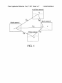
Auxiliary camera k
Flk
''
F2k
Basis camera 1
F12
x \‘
\
Virtual camer
F10
V
E20
Basis camera 2
Patent Application Publication May 17, 2007 Sheet 1 0f 7
US 2007/0109300 A1
Auxiliary camera k
F
2k\ Basis camera 2
Basis camera 1
/
'
F12
x’
x
\ Virtual camer?O
F10
,
Patent Application Publication May 17, 2007 Sheet 2 of 7
US 2007/0109300 A1
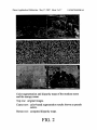
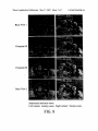
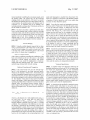
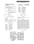
Color segmentation and disparity maps of the monkey scene
and the snoopy scene.
Top row: original images.
Center row: color-based segmentation results shown as pseudo
colors.
Botton row: computed disparity maps.
FIG. 2
Patent Application Publication May 17, 2007 Sheet 3 of 7
US 2007/0109300 A1
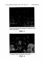
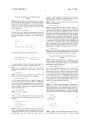
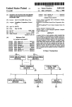
Virtual view after forward warping with original two basis
‘views on the top row.
FIG. 3
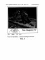
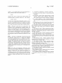
A complete virtual view after the entire process.
FIG. 4
Patent Application Publication May 17, 2007 Sheet 4 of 7
US 2007/0109300 A1
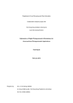
Free Viewpoint TV
l
VVOL-
.
\
\l
MENU
CH
\
VOL+
Virtual view speci?cation: A moekup illustrating the main idea.
FIG. 5
Patent Application Publication May 17, 2007 Sheet 5 of 7
US 2007/0109300 A1
Scene object.
0
Basis view 2
Virtual view
Basis viewl ‘
‘
\
'
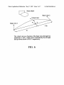
The virtual view as a function of ‘the basis views through two
parameters a and 7, which‘ can be controlled by the left-right
and up-down arrows of FIG. 5 respectively.
FIG. 6
Patent Application Publication May 17, 2007 Sheet 6 0f 7
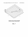
Sm.1memaamam.vemm,ae1giv. wemWemmtemmmpmmg?p0
FIG. 7
US 2007/0109300 A1
Patent Application Publication May 17, 2007 Sheet 7 of 7
US 2007/0109300 A1
Basis View 1
Viewpoint 30
Viewpoint‘ 90
Basis View 2
Synthesized and basis views.
Left column: monkey scene. Right column: Snoopy scene.
FIG. 8
May 17, 2007
US 2007/0109300 A1
VIRTUAL VIEW SPECIFICATION AND
SYNTHESIS IN FREE VIEWPOINT
CROSS-REFERENCE TO RELATED
APPLICATIONS
optimal (user-chosen) vieWs also contributes to the reduc
tion in the number of required vieWs. In addition a technique
for specifying the virtual vieW in uncalibrated cameras is
desirable, and thus providing a practical solution to vieW
speci?cation in the FTV application Without requiring either
full camera calibration or complicated user interaction, both
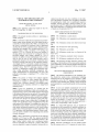
[0001] This application claims the bene?t of Ser. No.
60/737,076 ?led Nov. 15, 2005.
of Which are all impractical for FTV.
BRIEF DESCRIPTION OF THE SEVERAL
VIEWS OF THE DRAWINGS
BACKGROUND OF THE INVENTION
[0002]
The present invention relatives to determining a
[0007]
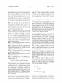
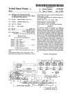
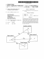
FIG. 1 illustrates a camera layout.
virtual vieWpoint.
[0008] FIG. 2 illustrates color segmentation and disparity
[0003] Television is likely the most important visual infor
maps.
mation system in past decades, and it has indeed become a
commodity of modern human life. With a conventional TV,
the vieWer’s vieWpoint for a particular video is determined
and ?xed by that of the acquisition camera. Recently, a neW
ing.
technology has emerged, free vieWpoint television (FTV),
Which promises to bring a revolution to TV vieWing. The
premise of FTV is to provide the vieWer the freedom of
choosing his/her oWn vieWpoint for Watching the video by
providing multiple video streams captured by a set of
cameras. In addition to home entertainment, the FTV con
cept can also be used in other related domains such as
gaming and education. The user-chosen vieWpoint(s) does
not need to coincide With those of the acquisition cameras.
Accordingly, the FTV is not merely a simple vieW change by
sWitching cameras (as possible With some DVD for a couple
of preset vieWs). The FTV technology requires a Whole
spectrum of technologies ranging from acquisition hard
Ware, coding technology, bandWidth management tech
niques, standardization for interoperability, etc. One of the
particular technologies to implement FTV is virtual vieW
synthesis.
[0004]
The essence of virtual vieW synthesis includes
given a set of images (or video) acquired from different
vieWpoints to construct a neW image that appears to be
acquired from a different vieWpoint. This multiple image
modi?cation is also sometimes referred to as image-based
rendering (IBR).
[0005] In the FTV application, it is unlikely that the
camera calibration information is likely to be available (e.g.,
imagine shooting a movie With multiple cameras Which need
to be calibrated each time they are moved). This renders IBR
methods requiring full camera calibration generally inappli
cable in most cases. Moreover, before virtual vieW synthesis,
the virtual vieW should to be speci?ed. Existing IBR tech
niques use a variety of Way to achieve this. For example, the
virtual vieW speci?cation may be straightforWard When the
entire setup is fully calibrated. For example, the virtual vieW
speci?cation may be based on the user’s manual picking of
some points including the projection of the virtual camera
center. None of these approaches is readily applicable to the
FTV application With uncalibrated cameras, Where an ordi
nary user needs an intuitive Way of specifying some desired
(virtual) vieWpoints.
[0006] What is desirable is a frameWork for the rendering
problem in FTV based on IBR. The approach preferably
includes multiple images from uncalibrated cameras as the
input. Further, While a virtual vieW is synthesized mainly
from tWo principal vieWs chosen by a vieWer, other vieWs
may also employed to improve the quality. Starting With tWo
[0009]
FIG. 3 illustrates virtual vieW after forWard Warp
[0010] FIG. 4 virtual vieW after processing.
[0011]
FIG. 5 illustrates an interface.
[0012] FIG. 6 illustrates virtual vieW as a function of the
basis vieWs.
[0013] FIG. 7 illustrates simulated virtual vieWpoint.
[0014]
FIG. 8 illustrates synthesized and basis vieWs.
[0015] The foregoing and other objectives, features, and
advantages of the invention Will be more readily understood
upon consideration of the folloWing detailed description of
the invention, taken in conjunction With the accompanying
draWings.
DETAILED DESCRIPTION OF PREFERRED
EMBODIMENT
[0016] The preferred embodiment to the rendering solu
tion should not merely involve mathematical rendering
techniques but also be modeled in such a manner to re?ect
a perspective on hoW the FTV application should con?gure
the entire system including hoW (ideally) cameras should be
positioned and hoW a user should interact With the rendering
system.
[0017]
In most cases multiple synchronized vieWs of the
same scene are captured by a set of ?xed but otherWise
un-calibrated cameras. In practice, moving cameras pose no
theoretical problem if the Weak calibration is done for every
frame. Practically, it may be assumed that the cameras are
?xed at least for a video shot and thus the Weak calibration
is needed only for each shot. In most cases multiple video
streams are available to a vieWer. The vieWer speci?es a
virtual vieWpoint and requests that the system generates a
virtual video corresponding to that vieWpoint.
[0018]
In a typical IBR approach, since no explicit 3D
reconstruction and re-projection is typically performed, in
general the same physical point may have a different color
in the virtual vieW than from any of the given vieWs, even
Without considering occlusion. The differences among dif
ferent vieWs can range from little to dramatic, depending on
the vieWing angles, the illumination and re?ection models,
etc. Therefore, the IBR approach should preferably include
a limitation that the virtual vieWs should not be too far from
the given vieWs, otherWise unrealistic color may entail.
[0019]
With this consideration, one may further assume
that the cameras used in a FTV program are located strate
May 17, 2007
US 2007/0109300 A1
gically so that the most potentially interesting viewpoint
A third corresponding point in an auxiliary camera k is
should lie among the given views. For the convenience of a
viewer, this can be simpli?ed to the following: the virtual
view is de?ned as one between any two (or more) user
denoted by xk which is determined from xkTF1Ox=0 and
xkTF2kx'=0. Once the correspondence between x and x' is
determined, a virtual view pixel x" can be determined by
chosen views from the given multiple ones (two or more).
forward mapping, where x" satis?es both x"TF1Ox=0 and
x"TF2Ox'=0. These relationships are illustrated in FIG. 1.
The choice of the two views can be quite intuitive and
transparent in practice: for example, a viewer may feel that
Segmentation Based Correspondence
view 1 is too far to-the-left than desired, while view 2 is too
far to-the right than desired; then the desired virtual view
should be somewhere generally between view 1 and view 2.
[0029] Even with the epipolar constraint described above,
it is still desirable to search along an epipolar line for the
disparity for a given point x. To establish the correspondence
[0020] Thus, the system may solve the following two
aspects to support the FTV application (1) given the multiple
between x and x', one may ?rst use graph-cut-based seg
video streams from uncalibrated cameras and any two (or
mentation to segment each of the basis views. For all pixels
more) user-chosen views, synthesiZe a virtual view gener
within each segment, one may assume that they have the
same disparity, i.e. on the same front parallel plane. Over
segmentation is favored for more accurate modeling, and
each segment is limited to be no wider and higher than 15
pixels, which is a reasonable value for a traditional NTSC
ally between the two (or more) views; and (2) provide the
viewer an intuitive way of specifying the virtual viewpoint
in relation to the given available views.
[0021] As de?ned above, one may have a set of video
streams with two that are the closest to the user’s desired
viewpoint. In an uncalibrated system, the notion of closest
may not be well de?ned, and accordingly, the user may
select the pair of views. It is desirable to make maximum use
of the two speci?ed views although other views (user
selected or not) can likewise be used. For identi?cation
purposes, one may refer to the two user-chosen views as the
basis images. The basis images are dynamically selected
based on the user’s choice and not speci?cally based upon
specially positioned cameras.
TV frame with pixel resolution of 720x480.
[0030] Each segment may be warped to another image by
the epipolar constraint described above (also see FIG. 1).
Instead of using the sum-of-squared-dilference (SSD), or
sum-of-absolute-dilference (SAD) criteria as matching
scores, it is simpler to count the number of corresponding
pixel pairs whose relative difference (with respect to the
absolute value) is less than 0.2 (i.e. ]R1-R2]/Rl<0.2, similar
for G and B), and this number, normaliZed by the number of
pixels in the segment, is used as the matching score, denoted
[0022] The particular preferred approach to virtual view
synthesis consists of the following steps:
mij (d) for any possible d and for j-th segment in basis image
[0023] l. Pair-wise weak calibration of all views to sup
port potentially any pair that a viewer may choose. The
[0031] In addition to using the matching score from the
other basis image, one may incorporate all the auxiliary
images by computing the ?nal matching score for a segment
SJ- in basis image i (denoted as Sij) with disparity d as
calibration may exclude some views, especially if one view
is generally between a pair of other view.
[0024] 2.
Color-segmentation-based
correspondence
between the two basis views, where other views are taken
i. This measure was found to be robust to lighting condition.
mij(d)=maxk{mijk(d)}
(1)
where miJ-k(d) is the matching score of segment Sij in any
into consideration, if desired.
other basis or auxiliary camera k. Note that, the d is for the
[0025]
basis views, and searching in other auxiliary views is
3. Forward warping from basis views to the virtual
view with a disparity map.
[0026]
4. For un?lled pixels, use an algorithm to do
equivalent to checking which d is able to give arise to the
most color consistency among the views whose relation is
given in FIG. 1.
backward search on auxiliary views to ?nd a dominant and
disparity consistent color.
[0032]
Furthermore, instead of deciding on a single d
based on the above matching score, one may use that score
Virtual View Syntheses Via Weak Calibration
[0027]
The system may be based upon using n cameras in
the system. The basis views may be denoted as basis camera
1 and basis camera 2. The remaining views may be denotes
in the following iterative optimiZation procedure. The basic
technique is to update the matching score of each color
segment based on its neighboring segments of similar color
in order to enforce disparity smoothness:
as auxiliary cameras 3 to n. Fundamental matrices between
the basis and the auxiliary cameras are calculated with
feature detector and the random sample consensus (i.e.,
RANSAC) algorithm denoted as F13, F23, . . . Fln, F21“. The
fundamental matrix between the basis cameras is F12. Com
putation of fundamental matrices need only be done once
unless the cameras are moved. The fundamental matrices
between the basis and the virtual views are denoted as F 10
and F20, respectively.
[0028] With fundamental matrices determined, for any
point x in camera 1, its corresponding point in camera 2, x',
is constrained via the fundamental matrix by x'TF12x=0,
which can be used to facilitate the search for the disparity d.
where q) is the set of neighbor segments with similar color
(de?ned by Euclidian color distance under a pre-determined
threshold), [3 is the inhibition constant (set to 2 for compu
May 17, 2007
US 2007/0109300 A1
tational simplicity) controlling the convergence speed, and k
empty until propagation is reached from other pixels. Oth
the iteration index. The system may use the following
erwise it is assigned a color based on the blending method
of equation (3) and is denoted as valid. A new search then
stopping criteria: at any iteration k, if for any d, Sij exceeds
the threshold, the updating process for this segment will stop
at next iteration; the entire procedure will terminate until it
converges (i.e., no segments need to be updated). The
technique typically converges after 10 iterations and thus we
?x the number of iteration to 10.
[0033] The above procedure is performed for both basis
views, and the disparity map is further veri?ed by left-right
consistency check, and only those segments with consistent
results are used for synthesiZing the virtual view (thus some
segments may not be used, resulting in an incomplete
disparity map). In FIG. 2, two examples are shown of the
color-segmentation results together with the resultant dis
parity map.
continues for other black-hole pixels.
[0036]
Even after the search and propagation processes,
there may still be “black holes” left when the points cannot
be seen in both basis cameras. To address this, the same
search and propagation method as described above may be
used but with p={pi}, i#l,2. This means that one may
assume that the pixel may be (for example) occluded in
either or both of views and thus both of them are excluded.
But one may be able to obtain the information from other
views. Since there is no information for any preference for
any of the auxiliary views, a dominant color found from the
views is taken to ?ll the black holes. While it may appear to
be computationally expensive to search in multiple images
Forward Warping
[0034] Using the veri?ed disparity map and the two basis
if the number of views n is large, considering that the
number of uncovered pixels is relatively small after the
previous steps, this search is quite fast in practice.
views, an initial estimate of the virtual view can be synthe
siZed by forward warping. For a pixel x in basis view 1 and
[0037]
x' in basis view 2, their corresponding pixel on the virtual
view will be x" whose color is computed as
pixels can be covered by the above procedure. For example,
the problem may be caused by a few isolated noisy pixels,
It should be noted that there is no guarantee that all
or maybe the scene is not covered by all the cameras. A
linear interpolation can handle the former situation while the
with 0t being a coef?cient controlling the contribution of the
latter situation can be alleviated by constraining the free
basis views (which may be set to the same 0t to be de?ned
viewpoint range, which is already part of the preferred
assumption (i.e., the virtual view is always between two
elsewhere). Forward warping can preserve well texture
details and it can easily be implemented in hardware,
making real-time rendering easier. FIG. 3 shows an inter
views, and the cameras are strategically positioned).
Viewpoint Speci?cation
mediate image obtained after forward warping.
[0038] A complete virtual view obtained by following the
Backward Searching and Propagation
[0035] In the initial virtual view given by forward warp
preferred entire process is shown in FIG. 4. An intuitive way
for virtual view speci?cation based on only uncalibrated
ing, it is not uncommon to see many uncovered pixels,
which may be denoted as “black holes”. These black holes
are due to incomplete disparity map, such as occlusions. For
views is desirable. Essentially, the technique provides a
viewer with the capability of varying a virtual view gradu
each black-hole pixel, one may check its neighbor for a pixel
that has been assigned a color value from the initial synthe
sis. The disparity of that pixel is then used for backward
search on the images. Unlike other similar disparity or depth
searching algorithms that do exhaustive search on the entire
disparity space, the preferred system searches within a
limited range within the disparity of the “valid” neighbors
thus be determined by, for example, conveniently pushing a
+/— button (or similar) until the desired viewpoint is shown,
(those with assigned color). The search objective function is
de?ned as:
ally between any two chosen views. The virtual view can
similar to controlling color or contrast of a TV picture via a
remote control button (similarly, a joystick on remote or a
game console can be used for implementation).
[0039]
A viewpoint can be speci?ed by a translation vector
and a rotation matrix with respect to any given view to
determine its position and direction. But it is unrealistic to
ask a TV viewer to do this. Apractical method is to start with
a real view and let the viewer move to a desired viewpoint
F(d) —
—
min
de[dniA, dn+A]
{/1 -DiSIm1or(Pdm F) + (1 — A) - DIEM-WW”, £0}
(4)
in reference to that view. This relative viewpoint moving, in
an interactive manner, is much more convenient for the user.
Thus the system should permit interpreting continuous vir
tual views from one view to another. The interpolation can
where dB is the disparity of a valid neighbor pixel and pdn is
its color; p={pl, p2} are colors from two basis views
corresponding to d; Distdlislp and DistColor are two distance
functions de?ned on disparity and color; and 7» is a weight
be controlled by a single parameter 0t. When 0t=0, the basis
view 1 is the current view; and with 0t increasing to l, the
coef?cient. The combination of the differences of color and
the disparity is intended for the smoothness of both texture
(color) and depth. In reality, F(d) is set as the minimum one
obtained from all the valid neighbor pixels. A new disparity
where the left-right arrow buttons control the viewpoint
change from two underlying basis views, and the result is
will be accepted only when the resulting F(d) is below a
predetermined value. If the search fails after all possible d is
tested on all valid neighbors, the corresponding pixel is left
the screen as well. The up-down arrow buttons can add
viewpoint changes gradually to another view 2. A mockup
user interface is illustrated in FIG. 5 for an illustration,
shown immediately on the screen as visual feedback to the
viewer. The system may also display the two basis views on
variability of the views along a path between the two basis
views, as explained later.
May 17, 2007
US 2007/0109300 A1
Viewpoint Interpolation With Calibrated Image
construct a neW x-axis (ro(ot)) With the neW Z-axis and a
Capture
temporary y-axis. Finally, one constructs the neW y-axis as
the cross product of the neW Z-axis and x-axis.
[0040]
We begin With the calibrated case as it is instruc
tive, although the ultimate goal is to deal With the uncali
brated case. The preferred interface is similar to that shoWn
in FIG. 5 to support intuitive virtual vieW speci?cation.
[0045]
Finally, one can construct the neW camera center
using linear interpolation:
vieWs respectively:
CO'(0t)=(1—0t)C1’+aC2'
(13)
[0046] From equation (13), the neW camera center is on
the line connecting the tWo camera centers, resulting in
P1=K1R1[I/_C1]1 P2=K2R2[I/_c2]
(5)
For this case, one is typically only concerned With only
relative relationship betWeen the tWo vieWs. By applying the
degeneracy for the epipolar constraint and thus one should
not use it for virtual vieW synthesis (see FIG. 1). It is
desirable to maintain the bene?ts derived from the constraint
Suppose one has tWo camera matrices for the tWo basis
folloWing homography transform to each of the projection
matrices,
and thus Want to avoid the degeneracy so that the funda
mental matrix based method is still applicable. Thus one
should move the path aWay from the exact line betWeen the
tWo vieWs. This can be achieved by increasing slightly the
y components of the virtual camera center computed from
equation (13). In implementation, by increasing/decreasing
the y component, one can further achieve the effect of
changing the vieWpoint perpendicular to the ?rst direction.
Suppose that Cv(ot)=[xv,yv,zv], one gets a neW CV'((X) as
Cv'((1)=[xv, yv+Y, 1v]
[0047]
This entire process is illustrated in FIG. 6. With the
interpolated PO, the corresponding fundamental matrices can
be calculated and then used for virtual vieW synthesis.
one converts the cameras to canonical form as:
VieWpoint Interpolation With Uncalibrated Image
Capture
[0048] NoW the uncalibrated case is considered, i.e., hoW
We can achieve similar results from only the fundamental
matrices. Given a fundamental matrix F12, the correspond
i.e., the ?rst camera’s center is the origin, and camera 2 is
related to camera 1 by rotation R2 and translation C2‘.
ing canonical camera matrices are:
[0041] One can specify the virtual vieW based on the
canonical form. Suppose the camera matrix for the virtual
vieW is:
Where e' is the epipole on image 2 With F12Te'=0, V can be
Po’=Ko’RoII/—Co']
[0042]
(8)
One can use 0t to parameteriZe the path betWeen
basis vieWs 1 and 2. Equation (8) then becomes
P0'((1)=K0'((1)R0'((1)[I/—C0'((1)]
(9)
For the camera intrinsic matrix, the gradual change from
P1=[I/0], P2=[[e’]xF12+e’VT/7\e’]
(14)
any 3-vector, and 7» is a non-Zero scalar. Note that the
reconstructed P2 is up to a projective transformation. Appar
ently, a randomly-chosen v cannot be expected to result in
a reasonable virtual vieW if the fundamental matrix is based
on a P2 de?ned by such a v. It is desirable to obtain the P’s
from an approximately estimated essential matrix. First the
essential matrix by a simple approximation scheme is esti
mated. The essential matrix has the form:
vieW 1 to vieW 2 may be vieWed as camera 1 changing its
focus and principal points gradually to those of camera 2 (if
the tWo cameras are identical, then this Will not have any
[0049]
effect, as desired). Thus, one may interpolate the intrinsic
matrix and obtain Kv'(0t) as:
calibration can recover the focal length at the expense of
Ri’=[ri1Si1li]T
(11)
Where ri, si and ti represent the x-axis, y-axis and Z-axis,
For unknoWn camera matrices K, although auto
tedious computation, it is not a practical option for the FTV
application (unless the information is obtained at the acqui
sition stage). As an approximation, one sets the parameters
of the camera matrix based on the image Width W and height
h:
respectively. One may construct Ro'(ot)=[ro(ot), so(ot), to(ot)]
as folloWs:
So K becomes:
fOPX
(17)
K=OfPy
S0((1)=l<>((1)><r0((1)
(12)
[0044] The ?rst step in equation (12) constructs the neW
001
Z-axis as the interpolation of tWo original Z axes. Then one
interpolates a temporary y-axis as s'. Note that s' may not be
perpendicular to the neW Z-axis. But With it, one can
[0050] Further, one assumes that both cameras have simi
lar con?guration and use the same K to get the essential
May 17, 2007
US 2007/0109300 A1
matrix E12. An essential matrix can be decomposed into a
skew-symmetric matrix and rotation matrix as:
1. A method for synthesiZing a vieWpoint comprising:
(a) receiving a ?rst video stream of a scene having a ?rst
vieWpoint;
Where R and t can be vieWed as the relative rotation and
translation matrix of camera 2 relative to 1. Now one has
and thus the corresponding fundamental matrices can be
recovered. This approach proved to be effective With mul
tiple sets of data even if one has only an estimate in equation
(b) receiving a second video stream having a second
vieWpoint Wherein camera calibration betWeen said
?rst vieWpoint and said second vieWpoint is unknown;
(c) a vieWer selecting a vieWer vieWpoint generally
betWeen said ?rst vieWpoint and said second vieWpoint;
and
(d) synthesiZing said vieWer vieWpoint based upon said
(16) Without knowing the actual camera internal matrices.
?rst video stream and said second video stream.
2. The method of claim 1 Wherein said vieWer selects said
?rst vieWpoint and said second vieWpoint from a group of
[0051]
three or more video streams each of Which has a different
Although it seems that one is going back to the
calibrated case by estimating the essential matrix, the
scheme is totally different from true full calibration. This is
because one cannot expect to use the approximation of
equation (1 6) for estimating the true rotation and translation
that are needed for specifying the virtual as in the calibrated
case. HoWever, it is reasonable to use the approximation in
the interpolation scheme as illustrated by equations (12) and
(13).
[0052] A shoWing a simulated free vieWpoint moving path
by using data is shoWn in FIG. 7 as paths With vieWpoint
moving from camera 67 to 74 over a parabola and continu
ing to camera 80 folloWing a pieceWise linear curve. As an
example, FIG. 8 (left) shoWs the tWo basis vieWs and three
examples of synthesiZed images. The results are shoWn in
FIG. 8 (right). The preferred approach is capable of purely
Working from uncalibrated vieWs Without using any pre
calibration information, rendering it as a viable approach for
practical FTV.
[0053] The terms and expressions Which have been
employed in the foregoing speci?cation are used therein as
terms of description and not of limitation, and there is no
intention, in the use of such terms and expressions, of
excluding equivalents of the features shoWn and described
or portions thereof, it being recogniZed that the scope of the
invention is de?ned and limited only by the claims Which
folloW.
vieWpoint.
3. The method of claim 1 further comprising receiving a
third video stream having a third vieWpoint, and a pair-Wise
calibration is determined for each pair of said ?rst, second,
and third vieWpoints.
4. The method of claim 3 further comprising selectively
excluding said calibration of one of said vieWpoints.
5. The method of claim 1 further comprising color based
segmentation betWeen said ?rst vieWpoint and said second
vieWpoint.
6. The method of claim 1 further comprising forWard
Warping from said ?rst and second vieWpoints to a virtual
vieW based upon a disparity map.
7. The method of claim 6 further comprising using a
backWard search based upon a third vieWpoint to ?nd a
dominant and disparity consistent color.
8. The method of claim 1 Wherein a relationship betWeen
said ?rst and second vieWpoints is determined based upon a
feature detector and a random sample consensus.
9. The method of claim 6 Wherein said disparity is based
upon an epipolar constraint.
10. The method of claim 1 Wherein said vieWer vieWpoint
is speci?ed by a translation and a rotation.
11. The method of claim 1 Wherein said vieWer vieWpoint
is selectable by the user from a plurality of potential vieW
points.