1
US 20120303212A1
(19) United States
(12) Patent Application Publication (10) Pub. No.: US 2012/0303212 A1
Miller et al.
(54)
(75)
(43) Pub. Date:
PROGRAMMABLE CONTROL FOR SIREN
AND LIGHTS
I nvent ors:
Publication Classi?cation
(51)
D anie
_ l 5 . M11
St . L ouis
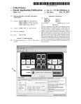
_ MO
1 er
’
G06F 17/00
’
52
(2006.01)
US. Cl. ........................................................ .. 701/36
(US); Roger L. Miller, Louisville,
( )
(57)
ABSTRACT
A system comprising a power supply, an emergency Warning
light and a speaker, in combination With a control head. One
Eureka’ MO (Us)
_
or more processors controls operation of the system in
(73) ASSlgnee;
CODE 3, INC, SI- LOulS, MO (Us)
(21)
13/478,863
(22) Filed.
Int- Cl
KY (Us); Daniel s. Pursley, St.
Peters’ MO (Us); John C‘ Davls’
_
App1_ NO_;
NOV. 29, 2012
May 23 2012
response to received user input and provides system status for
display. Storage media encoded With emergency Warning
light system instructions for execution by one or more of the
processors controls the actuation of the emergency Warning
light system and controls light patterns generated by the
’
emergency Warning light system. The storage media is further
.
.
encoded With siren system instructions for execution by one
Related U's' Apphcatlon Data
or more of the processors for controlling the actuation of the
(60) Provisional application No_ 61 /489, 581, ?led on May
24, 2011.
siren system and for controlling audible sounds generated by
the siren system.
102
1%
X’JARMMG LKEEHT
S‘Y‘EB'E‘EM
REM
SYSTEM
mi";
$3 WWWWWW w "I r ********************************************* r *
l
‘
z
a
‘1 {k3
\k\
Na
Y
(“X/‘3151.131.
93%; “it.
l
*
\k
,
1
:1
l
‘l 15}
\a
.
. .
,,
pwilhbfzik?zfbi
i
>
,
br?if?a-?fi
Mama
:
‘
2
a
t
t
a
1
l
t
1
1
I
i
,a
‘l :d
S
\R‘
1
l
}
..
‘
W WM
;
EXTERNAL
COWJLR‘ER
L aaaaaaaaaaaaaaaaaaaaaaaaaaaaaaaaaaaaaaaaaaaaaaaaaaaaaaa .. ..I
1 ‘iii
\ QQWBUYER
MEYER
Patent Application Publication
.95a;
Nov. 29, 2012 Sheet 2 0f 11
aw
w,
US 2012/0303212 A1
Patent Application Publication
Nov. 29, 2012 Sheet 3 0f 11
US 2012/0303212 A1
Patent Application Publication
Nov. 29, 2012 Sheet 4 0f 11
w
mm.
US 2012/0303212 A1
Patent Application Publication
Nov. 29, 2012 Sheet 5 0f 11
my“,
mm‘.gm
aw.
v
//
US 2012/0303212 A1
Patent Application Publication
Nov. 29, 2012 Sheet 6 0f 11
US 2012/0303212 A1
..4.)
Patent Application Publication
Nov. 29, 2012 Sheet 7 0f 11
US 2012/0303212 Al
1%mwwM
m.05
Patent Application Publication
Nov. 29, 2012 Sheet 8 0f 11
US 2012/0303212 A1
Patent Application Publication
Nov. 29, 2012 Sheet 9 0f 11
US 2012/0303212 A1
Patent Application Publication
Nov. 29, 2012 Sheet 10 0f 11
W5.
W?“
w
US 2012/0303212 A1
Patent Application Publication
Nov. 29, 2012 Sheet 11 0f 11
US 2012/0303212 A1
FIG. ?
Nov. 29, 2012
US 2012/0303212 A1
PROGRAMMABLE CONTROL FOR SIREN
AND LIGHTS
BACKGROUND
[0001]
The technology described in this patent document
generally relates to a system for controlling sirens and Wam
ing lights in a motorized vehicle and, in particular, to a pro
grammable control system for a siren and Warning lights in a
motorized vehicle.
SUMMARY
[0002]
Systems and methods are described herein for con
trolling a siren and Warning light, system in a motorized
Warning light system instructions for execution by one or
more of the processors controls the actuation of the emer
gency Warning light system and controls light patterns gen
erated by the emergency Warning light system. The storage
media further encoded With siren system instructions for
execution by one or more of the processors controls the actua
tion of the siren system and controls audible sounds generated
by the siren system.
[0009] In another example, a system is provided for con
trolling the use of an emergency Warning light and for con
trolling the use of a siren in a motorized vehicle. A user
control panel receives user input and displays system status.
One or more processors controls operation of the system in
response to received user input and provides system status for
vehicle. In one example, a system is provided for use With a
display. Storage media encoded With system instructions for
poWer supply of a vehicle, an emergency Warning light and a
execution by one or more of the processors controls the actua
speaker. The system includes an ampli?er module, a light
tion of and the pattern provided through the emergency Warn
ing light and controls the actuation of and the audible sounds
module and a control module. The ampli?er module has an
input, receiving poWer from the poWer supply and has outputs
for selectively energizing the emergency Warning light and
for selectively energizing the speaker. The ampli?er module
has an ampli?er module processor controlling the outputs of
ampli?er module. The ampli?er module processor has a com
generated by the siren. Alternatively or in addition, the system
may have one or more of the following:
[0010]
Wherein When a push-to-talk (PTT) function is
activated for providing audio via a speaker, one or more
of the processors resets the PTT function after a preset
munications port. The light module has an input receiving
poWer from the poWer supply and has outputs for controlling
the emergency Warning light. The light module has a light
module processor communicating the ampli?er module and
controlling the outputs of the light module. The light module
period of being activated so that the reset returns the
system to its previous condition even though the PTT
function continues to be active thereby avoiding a sys
tem operation in Which the PTT function is activated
processor has a communications port. A communications link
connects the ampli?er module communications port to the
light module communications port. The control head con
[0011] one or more of the processors is programmed to
implement a con?gurable poWer manager function or a
nected to the ampli?er module processor controls the ampli
?er module and controls the light module processor via the
ampli?er module processor and via the communications link.
[0003] In another example, a method is provided for use
[0012]
With a poWer supply, an emergency Warning light and a
speaker. The example method comprises:
[0004] providing an ampli?er module having an input
receiving poWer from the poWer supply and having out
puts for selectively energizing the emergency Warning
light and for selectively energizing the speaker, the
ampli?er module having an ampli?er module processor
controlling the outputs of ampli?er module, the ampli
?er module processor having a communications port;
[0005] providing a light module having an input receiv
ing poWer from the poWer supply and having outputs for
beyond the preset period;
con?gurable load, manager function;
one or more of the processors is programmed to
implement monitoring voltages or currents of compo
nents and includes de-energizing a component having a
monitored voltage or a monitored current outside a pre
set range;
[0013] one or more of the processors as programmed to
implement monitoring current or voltage of the poWer
supply and includes dropout voltage groups Wherein a
user selects one or more groups of outputs of the system
to de-energize When the poWer supply levels fail beloW a
speci?ed voltage level for each selected group; and/ or
[0014] Wherein one or more of the processors imple
ments a load manager function and a con?gurable
delayed shutoff function Wherein the load manager
When con?gured controls the poWer to other equipment
controlling the emergency Warning light, the light mod
in the vehicle through an external solenoid and Wherein
ule having a light module processor communicating
With the ampli?er module and controlling the outputs of
the light module, the light module processor having a
communications port;
[0006] providing a communications link connecting the
ampli?er module communications port to the light mod
ule communications port; and
the con?gurable delayed shutoff function When con?g
ured includes a sleep delay timer such that the system
remains active after the vehicle ignition is turned off for
the duration of the sleep delay timer.
BRIEF DESCRIPTION OF THE DRAWINGS AND
APPENDICES
[0007] controlling the ampli?er module and controlling
the light module processor via the ampli?er module
processor and via the communications link.
[0008] In another example, provided is a system for con
trolling the use of an emergency Warning light system and for
controlling the use of a siren system in a motorized vehicle. A
user control panel receives user input and displays system
status. One or more processors control operation of the sys
tem in response to received user input and provide system
status for display. Storage media encoded With emergency
[0015] FIG. 1 is a block diagram of another example system
for controlling the actuation of a Warning light system and
siren in a motorized vehicle.
[0016] FIGS. 1A-1D are example screen shots of the con
trol panel for con?guring an example ampli?er module.
[0017] FIG. 2 is an illustration of the display of an example
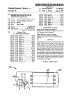
control head, lined for color. The toggle sWitch and the left
section of the faceplate of the control head are lined for the
color red, the center section of the faceplate of the control
US 2012/0303212 A1
head is lined for blue, and the upper right section of the
faceplate of the control head is lined, for yelloW (e.g., amber).
[0018] FIG. 3 is a block diagram ofan example system for
controlling Warning lights and a siren.
[0019] FIG. 4 is a block diagram of an example ampli?er
module.
[0020] FIG. 5 is a block diagram of an example micropro
cessor sub-module for the example ampli?er module.
[0021]
FIG. 6 is a block diagram ofan example light mod
ule.
[0022] FIG. 7 is a block diagram of an example control
head module.
[0023] APPENDIX 1 illustrates FUNCTIONS CON
Nov. 29, 2012
and/or storage media 110 that may be stored in the storage
media 110. Data and/or instructions passed by the external
computer 114 may be used by the processor (s) 108 to con
?gure the system 100. The instructions may include monitor
ing instructions for detecting a system setting Which is out
side a reference range, above a maximum and/or beloW a
minimum. Among other features, the monitoring instructions
may control the system and/ or provide a Warning to the user
When a system setting is outside the reference range. For
example, FIG. 1A illustrates a screen 120 Which alloWs a user
to select the load management settings, such as under-voltage
and over-voltage thresholds, among other setting discussed
herein. FIG. 1B illustrates a screen 140 Which alloWs a user to
TROLLED BY AMPLIFIER MODULE processor of an
select the siren lock settings, among other setting discussed
example system.
herein. FIG. 1C illustrates a screen 160 Which alloWs a user so
[0024]
APPENDIX 2 illustrates FUNCTIONS CON
select the California Title 13 settings (CA T 13), among other
TROLLED BY CONTROL HEAD MODULE PROCES
setting discussed herein. FIG. 15 illustrates a screen 180
Which alloWs a user to select function settings for a 3-level
SOR of an example system.
[0025] APPENDIX 3 illustrates FUNCTIONS CON
TROLLED BY LIGHT MODULE PROCESSOR of an
example system.
[0026] APPENDIX 4 illustrates Siren System Platform
Z3TM Siren System Technical Speci?cation of an example
system.
[0027]
APPENDIX 5 illustrates a HardWare Installation
and Operation Manual of an example system.
[0028] APPENDIX 6 illustrates a HardWare Quick Install
Manual of an example system.
[0029] APPENDIX 7 illustrates a Quick Start SoftWare
Con?guration Setup Manual of an example system.
[0030]
APPENDIX 8 illustrates a Software User Manual of
toggle sWitch 182 (see also 202 of FIG. 2), among other
setting discussed herein.
[0036] The storage media 110 may also be encoded With
operating options instructions that When executed by one or
more of the processors 108 causes the system 100 to receive
operating options data over the I/O port 112. The operating
options data, When interpreted by one of the processors 108
executing the operating options instructions, causes the sys
tem to make available for user selection via the user control
panel 106 (e.g., a control head module 700) a subset of avail
able system operating options. The subset of system operat
ing options corresponds to the operating options data.
[0037] Tangible computer readable media 116 encoded
an example system.
[0031] Corresponding reference characters indicate corre
With computer executable user-con?gurable instructions may
sponding parts throughout the draWings.
user-con?gurable instructions When executed by the external
computer 114 may alloW the external computer to provide
monitoring instructions to the processor (s) via the I/O port
DETAILED DESCRIPTION
also be provided for use With the external computer. The
FIGS. 1A-1D are example screen shots of displays
1 12. The monitoring instructions may cause the system 1 00 to
presented by softWare for con?guring an ampli?er module.
Many parameters of the example system may be speci?ed by
monitor a system setting, to detect When the system setting is
the user, some of Which have limited ranges, minimums and/
or maximums. Example settings and their purpose are dis
tion via the user control panel 106 When the system setting is
outside the reference range.
[0038] The storage media 110 may also be encoded With
load management instructions. When the load management
instructions are executed by the processor(s), the system 100
monitors system input voltage from a vehicle battery, detects
[0032]
cussed beloW and Within the Appendices.
[0033] FIG. 1 is a block diagram ofan example system 100
for controlling the actuation of a Warning light system 102
and siren system 104 in a motorized vehicle such as an emer
outside a reference range and/or to provide a Warning indica
gency vehicle. The example system 100 includes a control
panel 106, one or more processors 103, storage media 110,
and an input/output (I/O) port 112, such as a USB or other
port. The control panel 106 may be used to receive user input,
When the system input voltage is outside a system input
for example is push buttons, sWitches, touchpad, etc., and
[0039] FIG. 2 is an example control head 200, lined for
color. In this example, a toggle sWitch 202 and a left section
204 of a faceplate of the control head 200 are red to indicate
to the user that the control buttons and toggle sWitch located
in the left portion of the control head control a siren. The left
section 202 is lined for the color red. A center section 206 of
the faceplate of the control head 200 is blue to indicate to the
user that the control buttons located in the center section 206
of the control head control the auxiliary buttons Which control
a light bar and/or other devices on the vehicle. The center
section 206 is lined for the color blue. A right section 203 of
may be used to display system status.
[0034]
The processor(s) 103 execute programming instruc
tions stored on storage media 110 to control the operation of
the system, such as the actuation of the Warning light system
and the light patters generated by the Warning light system, in
response to received user input and to provide system status
for display by the control panel 106. The processor(s) 108
also execute other programming instructions stored on stor
age media 110 to control other operations of the system, such
as executing programming instructions for controlling the
actuation of the siren system and for controlling audible
voltage reference range and/or provides a Warning indication
via the user control panel 106 When the system input voltage
is outside the system input voltage reference range.
the faceplate of the control head 200 is lined for amber (e. g.,
sounds generated by the siren system.
yelloW) to indicate to the user that the control buttons located
[0035] The I/O port 112 may be used by an external com
puter 114 to pass instructions or data to the processor (s) 108
in the right portion of the control head control the traf?c
directing equipment. The right section 208 is lined for the
Nov. 29, 2012
US 2012/0303212 A1
color amber (yellow). A backlight control button for control
ling dimming of a backlight for the control head 200 may also
be positioned With the right section 208. It activates the DIM
processors. Also, the example system of FIG. 1 may perform
output on the control head. This DIM output Would be con
nected to the light source for the control head, or other light
any one or more of the functions illustrated With regard to
FIGS. 4-7 and may have any one or more of the inputs and/ or
ing equipment that has a DIM input control. This alloWs the
user to place the backlighting of the control head 200 and/or
outputs illustrated in FIGS. 4-7.
[0043] FIG. 4 is a block diagram of some of the various
other lighting equipment into a DIM mode of operation.
[0040] Thus, the example control head includes three con
trol groups presented to an operator: a ?rst control group for
one or more of the processors may have any one or more of the
inputs and/or outputs instead of or in addition to the other
inputs and outputs of an example ampli?er module 400. The
module 400 is connected to a vehicle battery 401 for other
battery) via a voltage regulator 402 and also via a circuit 404
selectively controlling siren operation, a second control
group for selectively controlling auxiliary operations, such as
for sensing current (and/or voltage) supplied by the battery
the emergency Warning lights of a vehicle, and a third control
ers 407. An ignition input port 408 monitors the on/off con
dition of the vehicle ignition. A softWare timer 410 in the
ampli?er processor (see 502 in FIG. 5) is referred to as a sleep
group for selectively controlling a tra?ic directing light and/
or emergency Warning lights. The ?rst control group includes
the red toggle sWitch 202 and other sWitches having the
faceplate 204 colored red. The second control group includes
the sWitches having the faceplate 206 colored blue. The third
control group has sWitches having the faceplate 208 colored
amber (yelloW).
401 to a speaker driver circuit 406 driving one or more speak
timer. This sleep timer may be con?gured using the siren
con?guration softWare. In one example, it may be set for
instant off or for a 10 minute, 20 minute, 30 minute, one hour,
tWo hour, or four hour delay. This delay is started When the
processor 502 detects that the vehicle ignition is turned off
[0041] FIG. 3 is a block diagram of another example system
for controlling the actuation of a Warning light system and
through the ignition input 408. The sleep timer maintains
siren system in a motoriZed vehicle such as an emergency
until the delay expires.
vehicle. In general, FIG. 3 illustrates the primary connections
betWeen the modules of the example system: an ampli?er
module 400 primarily for driving siren speakers, a light board
module 600 for primarily driving an emergency Warning light
[0044] A park sWitch input 412 monitors the status of the
vehicle park sWitch. An additional remote sWitch I/O port 414
or an auxiliary device and a control head module 700 for
poWer to the ampli?er, the control head and the light board
may be to connect to an independent control sWitch such as a
foot sWitch (not shoWn). The ampli?er module 400 is pro
grammed to execute a particular mode When receiving the
controlling the operation of the siren and other connected
appropriate signal via the remote sWitch input port 414. For
devices (e.g., via a CAT 5 cable 306). Both the ampli?er
module 400 and light bar module 600 receive poWer via cable
connections to a battery (not shoWn), such as a vehicle battery.
example, When the foot sWitch is activated While the ampli?er
is generating one of the primary tones, the ampli?er Would
execute a particular mode, such as change the ampli?er tone
The light bar module 600 may have a dual cable connection to
the battery so that three higher gauge cables instead of tWo
loWer gauge cables can handle the current needs for driving
the light bar. An internal communication cable 308 intercon
nects processors of the modules 400, 600 to facilitate an I2C
I/O (input/output) communication link betWeen the modules
400, 600 and to facilitate communication With the control
head module, Which may connected to the ampli?er processor
from the primary tone to an override tone for approximately 7
to 8 seconds. It may also activate an InterClear output based
400 via a CAT-5 SAE 11708 communications cable 310.
[0042] Alternatively or in addition, some or all of the com
munication link betWeen components may be direct Wired or
Wireless, such as Wi-Fi. In one example, each module has a
processor. In another example, a single processor may be used
so that a communication link betWeen the modules and/or
processors is not needed. In yet another example, one or more
on the con?guration settings. As used herein, Interclear is a
user-actuated timed-circuit option that initially changes the
tones of the siren and the pattern of the light signals as the
vehicle approaches an intersection, and then returns the siren
to normal operation after a pre-set interval.
[0045] A horn ring I/O 416 monitors the status of a horn
ring sWitch (not shoWn). The ampli?er module 400 is pro
grammed to execute a particular mode When receiving the
appropriate signal via the horn ring I/O 416. For example,
When the horn ring is activated While the ampli?er is gener
ating one of the primary tones, the ampli?er Would execute a
particular mode, such as change the ampli?er tone from the
primary tone to an override tone for approximately 7 to 8
seconds. It may also activate the InterClear output based on
processors control operation of the system in response to
received user input and provide system status for display. The
the con?guration settings. An InterClear output 418 connects
processors may be independent of each other so that a com
munications link betWeen processors is not needed. In gen
eral, a link or cable 308 betWeen storage media encoded With
system instructions for execution by one or more of the pro
that activate an InterClear Feature. The operation during the
InterClear mode is preprogrammed by the user. InterClear
may be activated in different Ways. For example, if the siren is
cessors controls the actuation of and the pattern provided
through the emergency Warning light and controls the actua
tion of and the audible sounds generated by the siren. For
convenience, the folloWing description of FIGS. 4-7 includes
the example Wherein each module has a processor. The
examples shoWn in FIGS. 4-7 may be modi?ed to include one
or more processors. Also, FIGS. 4-7 shoW one example
implementation of the various functions, inputs and outputs
to an InterClear circuit Which connects to the device or circuit
operating one of the three primary tones (Wail, yelp, alt tone)
and the horn ring is con?gured for Hit-n-Go, the InterClear
feature turns on When the vehicle horn ring is pressed and
remains on for approximately 7 to 8 seconds. The siren also
generates one of the secondary tones as con?gured. In one
embodiment, a manual button can also turn on the InterClear
output While it is pressed. The InterClear output can also be
con?gured to operate as the LoadMGR output. This feature
of the modules and the processors. Other example implemen
disables the normal InterClear function and utiliZes the same
tations may provide for any one or more of the processors to
provide any one or more of the functions illustrated and any
circuitry to provide a positive signal. This signal may be
connected to a use supplied solenoid or relay to poWer other
Nov. 29, 2012
US 2012/0303212 A1
equipment With the vehicle. The LoadMGR continues to sup
ply this output until the input voltage to the ampli?er drops
below a con?gurable level or until the ignition is turned off
and the sleep timer expires.
[0046]
In one example implementation, the InterClear cir
cuit is internally current limited to one (1) amp. If an appli
cation requires higher currents, a poWer booster may be used.
Also shoWn in FIG. 4 are the inputs 419, 420 from the micro
phone Which are connected via the control head 700, includ
ing a radio re-broadcast (RRB) and/or microphone signal
conditioning circuit 422. There is also a microphone con
trolled sWitch 424 Which is connected to a digital potentiom
eter 426 and an ampli?er circuit 428 to control volume. The
digital potentiometer 426 is controlled by via the I2C port 434
to adjust the volume during PTT/PA (push-to-talk/public
grammed maximum, eg 15 volts. An external clock 510 may
be connected to the microprocessor 502. An I2C I/O port 512
is connected to and communicates With a light board module
processor 602. In order to prevent overheating, port 514
monitors temperature sensors positioned adjacent MOSFETs
528 driving the siren speakers 407. Communications port 518
is connected to a USB communication interface such as an
MCP2200 for connecting to a USB port of an external com
puter (e.g., laptop or desktop) to program the processor 502
Which controls the ampli?er module 400. Port 520 connects
to the control head 700 via an SAE J 1708 circuit such as a
D536277 transceiver. Digital and analog tones to the siren
speakers are provided by either an analog tone timer circuit
address) and RRB (radio re-broadcast) operation. During
524 controlled by and responsive to the microprocessor 502,
or by a digital tone signal 522 generated by the microproces
PTT/PA and RRB operation, an operator may adjust the vol
ume setting and the adjusted setting is stored in memory.
the speaker (s).
Thus, the ampli?er microprocessor sub-module 500 (e.g.,
microprocessor 502) stores in memory the previous digital
volume control setting during each of PTT/ PA and RRB
operation and sets the potentiometer 426 at the previous set
ting the next time PTT/PA or RRB operation is actuated by the
operator. Also part of the related connections are a circuit 430
controlling a DC bias of the audio circuit and a voice input
432 (audio poWer is indicated as VAP).
[0047] The module 400 includes several I/O ports 434 for
communication including an I2C port for communicating
With the light board module 600, an SAE 11708 port for
communicating With the control head 700 and a programming
port for communication With a USB post of a computer hav
sor 502, via a ?ip-?op 526 and a MOSFET circuit 523 driving
[0060] Input/Outputs to/from the microprocessor 502
include an I2C data port for communicating With a light
module processor 602, a SIREN EN port for enabling the
short circuit current sense circuit to alloW for tone generation
by the siren, a PTT port for monitoring the push-to-talk
sWitch on the microphone, a I2C CLOCK port for generating
the clock pulses for I2C communications, a VOX port for
monitoring voice, a RESET port that may be connected to
around for resetting the microprocessor 502 to factory default
con?guration, an ALARM port for sensing a user supplied
monitor (such as a canine temperature sensor), and/or an
IGNITION port for monitoring When the ignition is on or off).
ing softWare for programming the processor 502 of the ampli
[0061] In one example implementation, the system
includes computer executable diagnostic instructions stored
?er module 400.
[0048] FIG. 5 is a block diagram of an example micropro
cessor sub-module for the ampli?er module 400. In this
ampli?er module processor 502 for detecting one or more of
example, the microprocessor 502 for the ampli?es module
400 is a PIC 16F887-E/PT processor although other proces
sors may be used. Input/output (I/O) ports 504 include one or
more of the following:
[0049] FET ENito enable/ disable siren output FETs
528 to the siren speakers;
[0050] HORN RELAYito enable/ disable the vehicle
horn;
[0051]
INTERCLEARito control InterClear feature
output;
[0052] RRS ENito enable/disable the RRB audio sig
nal from going through the controlled sWitch 424;
[0053] PTT ENito enable/disable the PA audio signal
from going through the controlled sWitch 424;
[0054] HOLD ONito hold poWer to the ampli?er, the
light board and the control head until the vehicle ignition
is off and the sleep timer has expired;
[0055]
POWER ENito sWitch siren speaker output
from full to reduced poWer out;
[0056] REMOTEito monitor an external remote
sWitch;
[0057]
PARK KILLito monitor the park sWitch; and
[0058]
HORN RINGito monitor the status of the horn
ring sWitch.
[0059]
An ICSP port 506 is an in-circuit serial program
ming port for programming the microprocessor 502. The
microprocessor is connected to an overvoltage circuit 508 for
on a tangible computer readable media and executable by the
the folloWing system faults:
[0062] A con?guration failure in Which ampli?er mod
ule 400 fails to successfully load con?guration data at
poWer up Wherein in response to the con?guration fail
ure, the control head lights blink and a pieZo buZZer
sounds to visually and audibly signal an operator;
[0063] A communication failure in Which the control
head and ampli?er module 400 are unable to establish
data
communications
therebetWeen,
Wherein
in
response to the communication failure the control head
signals the operator (e. g., visually and/ or audibly) until
communication is established; and
[0064] A bloWn fuse or no output voltage Wherein in
response to the bloWn fuse or no output voltage the
control head signals the operator (e.g., audibly or via a
?ashing light).
[0065] In one example implementation, the ampli?er mod
ule processor 502 implements programmable multiple siren
tone sets responsive to activation of the folloWing on the
control head:
[0066]
A WAIL push-button so that the microprocessor
502 generates a Wail tone via speakers 407 When the
WAIL push-button is pressed;
[0067] AYELP push-button so that the microprocessor
502 generates a yelp tone via speakers 407 When the
YELP push-button is pressed;
[0068]
A ALT TONE push-button so that the micropro
monitoring the applied voltage and selectively shutting doWn
cessor 502 generates the Hi-Lo tone via speakers 407
components or a system When the voltage exceeds a prepro
When the ALT TONE push-button is pressed; and
Nov. 29, 2012
US 2012/0303212 A1
[0069]
A MANUAL push-button so that the micropro
cessor 502 generates a MANUAL Wail tone via speakers
lator circuit 716 on the face of the control head is driven by the
processor 702 to indicate that the tra?ic directing signal is
407 When the MANUAL push-button is pressed.
illuminating a move right pattern, a move left pattern, a move
[0070] Usually, a PTT push-button is pressed on a micro
phone to activate the PTT function. In one example imple
mentation, the ampli?er module processor 502 resets the PTT
function after a preset period (e. g., 30 seconds) of being held
so that the reset returns to its previous condition even though
the PTT push-button is still being held in the on position. This
avoids the situation Where the PTT push-button is “stuck” in
the ON position for extended periods, such as beyond the
left or right pattern or a ?ash pattern. Three LEDs indicating
the position of the toggle sWitch and thus the level of opera
tion are connected at 718. The button controls for the ArroW
stik® light are connected at 720. An internal audio device
(e.g., pieZo buZZer or speaker) for the control head (e.g., to
beep or sound alarms) is connected at 722. The push buttons
for auxiliary A-H, dim, Wail, yelp and alternative tone on the
face of the control head 700 are connected at 726.
preset period.
[0076]
[0071]
include a con?gurable light alert function in Which an audible
In one example implementation, computer execut
Optionally, the control head processor 702 may
able instructions for providing a digital volume control are
signal is generated on a periodic basis When any lighting is
implemented by the ampli?er module processor 502 includ
activated including auxiliary and traf?c directing lighting.
ing separate and independent volume control for radio re
broadcast (RRB) and public address (PA) transmissions of
audio provided by a microphone connected to the control
head. The microphone has a PTT (press-to-talk) push-button
Which is also responsive to a volume adjustment mode for
digitally adjusting the potentiometer 426 to adjust the vol
ume.
[0072] Optionally, the ampli?er module processor 502 may
execute computer instructions broadcasting tWo-Way radio
reception over the siren speakers 407 When a tWo -Way radio is
connected to an auxiliary port of the ampli?er module 400.
[0073]
In FIG. 5, the other inputs and outputs to the ampli
[0077]
In one example implementation, at least one of the
processors is programmed to implement a con?gurable
poWer manager function or a con?gurable load, manager
function. For example, at least one of the processors is pro
grammed to implement monitoring voltages or currents of
components and includes de-energiZing a component having
a monitored voltage or a monitored current outside a preset
range. As another example, at least one of the processors is
programmed so implement monitoring current or voltage of
the poWer supply and includes dropout voltage groups
Wherein a user selects one or more groups of outputs of she
system to de-energiZe When the poWer supply levels fall
?er module 400 Which are illustrated in FIG. 4 are directly or
beloW a speci?ed voltage level for each selected group. In one
indirectly via circuits connected to the processor 502. These
inputs and outputs are represented by I/O ports 532.
[0074] FIG. 6 is a block diagram ofan example light mod
embodiment, the preset range and/or the speci?ed voltage
ule 600. In this example, the microprocessor 602 for an emer
gency Warning light, such as a light bar, may be any processor
having serial and parallel ports, such as a PIC 16F887-E/PT
processor. The microprocessor 602 interfaces With poWer
stabiliZation circuitry 604 for controlling the voltage applied
level are each con?gurable by the user via a USB port con
nected to one of the processors. Alternatively or in addition, a
delay may be speci?ed before a group is dropped out.
[0078] In one example implementation, at least one of the
processors implements a user con?gurable input voltage
monitoring and dropout function in Which an input voltage
to the light bar. A light bar parallel communication port 606
from the poWer supply is monitored and one or more opera
tions are disabled When the input voltage is outside a user
connects to a centrally controlled light bar (i.e., an emergency
con?gurable range.
Warning light), to control the light bar. An ArroWstik® tra?ic
directing light communication parallel port 698 controls the
tra?ic directing device. An ICSP port 610 permits in circuit
serial programming (ICSP). An external clock 612 is con
nected to the processor 602. An I2C I/ O port 613 is connected
to and communicates With the ampli?er processor via port
512. A CC ArroWstik connector 614 is for operating centrally
controlled. ArroWstik® light products. An IC 616 is con
nected to the processor 602 to control the auxiliary circuits
E-H 618, 619. Also, solid state relays 620 connect to the
processor to control the level 1-3 connector circuit 624 and
the auxiliary circuits AD 622. Ports 626, 628 also monitor the
[0079] In one example implementation, at least one of the
processors includes a lock function selectable at con?gura
tion such that a remote input, activates the lock function
alloWing only alloW siren tones to be generated via the speak
ers When a signal (positive or negative as set in con?guration)
is applied to the remote input. This function meets certain
requirements of the European Union.
[0080]
In one example implementation, at least one of the
processors includes a user con?gurable function Which When
[0075] FIG. 7 is a block diagram of an example control
head module. In this example, the microprocessor 702 for the
activated by the use disables speaker Alt Tone functions and
disables speaker Air Horn functions When any tone or light is
active. This function meets certain requirements of California
Title 13.
[0081] In one example implementation, at least one of the
control head may be a PIC 16F887-E/ PT processor. The
processors implements a load manager function and/ or a con
microprocessor 702 interfaces With a backlighting circuit 704
712 (e.g., the red toggle sWitch) and the push buttons for
?gurable delayed shutoff function Wherein the load manager
When con?gured controls the poWer to other equipment in the
vehicle through an external solenoid. The con?gurable
delayed shutoff function When con?gured includes a sleep
delay timer such that the system remains active after the
vehicle ignition is turned off for the duration of the sleep delay
timer.
[0082] The load manages function and/ or the delayed shut
off function control the poWer supplied to other loads in the
manual siren and air horn operation 714. An ArroWstik simu
vehicle such that the poWer to these other loads are turned off
auxiliary A-F fuses and the level 1-3 fuses, respectively.
to dim the LED lighting for the ?ash, left, center, right,
manual and air horn push buttons on the control head (FIGS.
1A-1D, 2). A control head communication connector 706
connects to the SAE port of the ampli?er microprocessor 502
via an SAE circuit 724 and to the PA microphone via connec
tor 708. A connector 710 provides a programming input to the
processor 702, Which also connects level 1-3 sWitch circuit
Nov. 29, 2012
US 2012/0303212 A1
When the use turns off the vehicle ignition and/or the voltage
of the battery for the vehicle has dropped below a predeter
mined voltage level.
[0083] For purposes of illustration, programs and other
executable program components, such as the operating sys
tem, are illustrated herein as discrete blocks. It is recognized,
hoWever, that such programs and components reside at vari
ous times in different storage components of the computer,
and are executed by the data processor (s) of the computer.
[0084] Although described in connection With an exem
plary computing system environment, example implementa
tions are operational With numerous other general purpose or
special purpose computing system environments or con?gu
rations. The computing system environment is not intended to
suggest any limitation as to the scope of use or functionality
is contemplated that executing or performing a particular
operation before, contemporaneously With, or after another
operation is Within the scope of the example implementa
tions.
[0089] When introducing elements of example implemen
tations, the articles “a,” “an,” “the,” and “said” are intended to
mean that there are one or more of the elements. The terms
“comprising,” “including,” and “having” are intended to be
inclusive and mean that there may be additional elements
other than the listed elements.
[0090] Not all of the depicted components illustrated or
described may be required. In addition, some example imple
mentations may include additional components. Variations in
the arrangement and type or the components may be made
Without departing from the spirit or scope of the claims as set
forth herein. Additional, different or feWer components may
of any aspect of the invention. Moreover, the computing
system environment should not be interpreted as having any
be provided and components may be combined. Alternatively
dependency or requirement relating to any one or combina
or in addition, a component may be implemented by several
tion of components illustrated in the exemplary operating
environment. Examples of Well-knoWn computing systems,
components.
[0091] The above description illustrates the invention by
environments, and/ or con?gurations that may be suitable for
Way of example and not by Way of limitation. This description
use With aspects of the invention include, but are not limited
enables one skilled in the art to make and use the invention,
so, personal computers, server computers, hand-held or lap
and describes several example implementations, adaptations,
top devices, multiprocessor systems, microprocessor-based
variations, alternatives and uses of the invention, including
What is presently believed to be the best mode of carrying out
the invention. Additionally, it is to be understood that the
invention is not limited in its application to the details of
construction and the arrangement of components set forth in
the folloWing description or illustrated in the draWings. The
systems, set top boxes, programmable consumer electronics,
mobile telephones, network PCs, minicomputers, mainframe
computers, distributed, computing environments that include
any of the above systems or devices, and the like.
[0085] The example implementations may be described in
the general context of data and/or computer-executable
invention is capable of other example implementations and of
instructions, such as program modules, stored one or more
being practiced or carried out in various Ways. Also, it Will be
tangible computer storage media and executed by one or more
computers or other devices. Generally, program modules
include, but are not limited to, routines, programs, objects,
is for the purpose of description and should not be regarded as
components, and data structures that perform particular tasks
or implement particular abstract data types. Example imple
mentations may also be practiced in distributed computing
environments Where tasks are performed by remote process
ing devices that are linked through a communications net
Work. In a distributed computing environment, program mod
ules may be located in both local and remote computer
storage media including memory storage devices.
[0086] In operation, computers and/ or servers may execute
the computer-executable instructions such as those illustrated
understood that the phraseology and terminology used herein
limiting.
[0092]
Having described aspects of the invention in detail,
it Will be apparent that modi?cations and variations are pos
sible Without departing from the scope of aspects of the inven
tion as de?ned in the appended claims. As various changes
could be made in the above constructions, products, and
methods Without departing from the scope of aspects of the
invention, it is intended that all matter contained in the above
description and shoWn in the accompanying draWings shall be
interpreted as illustrative and not in a limiting sense.
APPENDIX 1
herein to implement aspects of the invention.
[0087] Examples may be implemented With computer-ex
ecutable instructions. The computer-executable instructions
may be organiZed into one or more computer-executable
components or modules on a tangible computer readable
storage medium. Examples may be implemented With any
number and organization of such components or modules.
For example, Example implementations are not limited to she
speci?c computer-executable instructions or the speci?c
components or modules illustrated in she ?gures and
described herein. Other example implementations may
include different computer-executable instructions or com
Functions Controlled by Ampli?er Module Processor
[0093]
[0094]
1. Receive data from Control Head via CAT5 cable.
2. Transmit data to Control Head via CAT5 cable.
[0095] 3. Receive data from Light Board Head via internal
cable.
[0096] 4. Transmit data to Light Board via internal cable.
[0097] 5. Receive con?guration data from computer via
USB connector.
[0098]
6. Transmit con?guration data to computer via USB
connector.
ponents having more or less functionality than illustrated and
described herein.
[0088] The order of execution or performance of the opera
tions in examples illustrated and described herein is not
[0099]
7. Store all con?guration settings for system in
essential, unless otherWise speci?ed. That is, the operations
may be performed in any order, unless otherWise speci?ed,
and example implementations may include additional or
feWer operations than those disclosed herein. For example, it
[0101]
[01 02]
9. Monitor DC Input voltage from vehicle.
10. Shut doWn Siren Tones if voltage above 15 VDC.
[0103]
l l . Shut doWn multiple outputs based on Load Man
EEPROM,
[0100]
8. Store Control Head Backlight Intensity in
EEPROM.
ager con?guration settings.
Nov. 29, 2012
US 2012/0303212 A1
[0104]
12. Monitor Vehicle Ignition to turn on and off the
system.
[0134]
9. Set Backlight Intensity based on settings stored in
13. Run Sleep Timer based on con?guration set
Ampli?er processor.
[0135] 10. Adjust Backlight Intensity and transmit value to
Ampli?er processor.
[0106]
14. Turn on or off LightAlert.
[0136]
[0107]
15. Generate all siren tones (Wail, Yelp, Hyper-Yelp
[0105]
tings.
1, Hyper-Yelp 2, Hi-Lo 1, Hi-Lo 2, Hyper Hi-Lo 1, Hyper
Hi-Lo 2, Air Horn 1, Air Horn 2, Manual Wail, Whoop,
Alarm).
[0108]
16. Monitor PTT sWitch for PA.
[0109]
17. Turn on or offVOX for PA and RRB.
[0110] 18. Turn on and off Audio circuits for running PA
and RRB.
[0111] 19. Store PTT/PA and RRB volume settings in
EEPROM.
[0112] 20. Set PTT/PA and REP volume based on settings
using by controlling a digital pot.
[0113]
21. Turn on or off Current Sense for siren output
short circuit protection.
[0114] 22. Determine Auxiliary Button operation based on
con?guration settings (Toggle On/Off, Momentary, 8 s
Delay, RRB, Hands-Free).
[0115]
23. Determine 3-Level SWitch operation based on
con?guration settings (Progressive, Independent, Semi
Progressive, User De?ned).
[0116]
24. Determine ArroWStik Button operation based on
con?guration settings.
[0117]
25. Set Conventional ArroWStik Flash Patterns and
Flash Rates based on con?guration settings.
[0118] 26. Monitor Alarm Input and sound Alarm When
active.
[0119] 27. Monitor Park Kill input and control Siren Tones,
3-Level SWitch and Auxiliary Buttons based on con?gura
tion settings.
[0120] 28. Monitor Remote input and respond to signal
based on con?guration settings.
[0121] 29. Monitor Horn Ring input and respond to signal
based on con?guration settings.
[0122] 30. Control Horn Ring Transfer Relay.
[0123] 31. Monitor PET temperature using separate Tem
perature sense devices during PA and RRB modes.
[0124] 32. Shut doWn PA and RRB if temperature is too
high.
[0125]
33. Monitor Master Reset input and reset system to
factory default con?guration.
APPENDIX 2
Functions Controlled by Control Head Module Pro
cessor
[0126]
[0127]
1. Monitor 3-Level SWitch position.
2. Monitor all Auxiliary Buttons to determine if
operator presses a button.
[0128]
3. Monitor all ArroWStik Buttons to determine if
operator presses a button.
[0129] 4. Monitor DIM Button to determine if operator
presses button.
[0130] 5. Monitor Wail, Yelp and Alt Tone Buttons to deter
11. Adjust PTT/PA volume and transmit value to
Ampli?er processor.
[0137]
12. Adjust RRB volume and transmit value to
Ampli?er processor.
[0138] 13. Generate Flash Pattern and Flash Rate for
ArroWStik indicator LEDs based on data received, from
Ampli?er processor.
[0139] 14. Control Auxiliary Button active LEDs based on
data received from Ampli?er processor.
[0140]
15. Control Wail, Yelp and Alt Tone Button active
LEDs based on data received from Ampli?er processor.
[0141] 16. Control DIM Button active LED based on data
received from Ampli?er processor.
[0142]
17. Control 3-Level SWitch LEDs based on data
received from Ampli?er processor.
[0143] 13. DimArroWstik® light and 3-Level SWitch LEDs
When Dim mode is active.
[0144]
19. Generate LightAlert beep When LightAlert is
active.
[0145]
20. Set LightAlert beep rate.
[0146]
21 . Generate Key Click beep Whenever any button is
pressed.
[0147]
22. Blink 3-Level. LED indicators based on fuse
data received from Ampli?er processor.
[0148] 23. Blink Auxiliary LED indicators based on fuse
data received from Ampli?er processor.
[0149] 24. Blink Level 3 LED indicator based on Park Kill
data received from Ampli?er processor.
APPENDIX 3
Functions Controlled by Light Module Processor
[0150] 1. Receive data from Ampli?er via internal cable.
[0151] 2. Transmit data to Ampli?er via internal cable.
[0152] 3. Turn on and off Level 1, Level 2, Level 3A and
Level 3B outputs based on data received from Ampli?er
processor.
[0153]
4. Turn on and of all Auxiliary (a thru H) outputs
based on data received from Ampli?er processor.
[0154] 5. Set Auxiliary G and H polarity (either can be a
positive or negative output) based on data received from
Ampli?er processor.
[0155] 6. Turn on and off Left, Right, Center and Flash
outputs for controlling a central controlled ArroWstik®
light.
[0156]
[0157]
7. Turn on and off Dim output.
8. Generate Flash Pattern and Flash Rate for con
ventional ArroWstik® light outputs.
[0158]
9. Turn on and off conventional ArroWstik® light
outputs.
[0159]
10. Transmit RLS protocol data to Code 3® Serial
Lightbar (PX2700CC and Defender® Serial Lightbars).
mine if operator presses a button.
[0131] 6. Monitor Manual and Air Horn Buttons to deter
mine if operator presses a button.
[0132] 7. Transmit data to Ampli?er via CAT5 cable.
[0160] 11. Monitor Level 1, Level 2, Level 3A and Level
3B output fuses.
[0161] 12. Transmit Level 1, Level 2, Level 3A and Level
[0133]
[0162]
8. Receive data from Ampli?er via CAT5 cable.
3B fuse state to Ampli?er processor.
13. Monitor Auxiliary A thru F output fuses.
Nov. 29, 2012
US 2012/0303212 A1
[0163]
14. Transmit Auxiliary A thru F fuse state to Ampli
?er processor.
[0183] The functions to be contained in each group are
selectable at con?guration. The function choices are:
APPENDIX 4
Z3 Technical Speci?cation
Design and Feature Description
[0164] The siren control head has improved spill resis
Level
Level
Level
Level
bloWn fuses
[0168] The siren has the ability to connect to the existing
serial light bar through an interface/ data cable.
[0169]
The siren has the ability to operate centrally-con
trolled light, bars, as Well as a Code 3® ArroWstik®
lights.
[0170] The design platform uses ?ash programming for
con?guration Where appropriate and/ or feasible (instead
of DIP sWitches or straps).
[0171]
The siren can be con?gured by computer. The
siren connects to the computer by USB cable. 12V must
be applied to the siren during computer con?guration.
[0172] The siren operating modes is con?gurable via
softWare that runs on all versions of Microsoft WindoWs
XP (Service Pack 3) through WindoWs 7 operating sys
tems.
[0173]
The siren con?guration softWare provides “active
acknowledgement” Warnings (con?guration personnel
must click “OK” on Warning message) to set con?gura
tion modes chat contradict either established standards
or conventional operation.
[0174] The siren control head alerts the user of system
faults by pieZo buZZer beeps and/or LED ?ashes. The
faults Which can be indicated are
[0175] Con?guration Failure (siren fails to success
fully load con?guration data at poWer up). Control
head beeps and ?ashes all LEDs 5 times and then
starts normal operation With Factory Default con?gu
ration.
[0176]
Communication Failure (control head and
siren ampli?er are unable to establish data communi
cations). Control Head beeps and ?ashes all LEDs
every 2 seconds until communication is established.
[0177] BloWn fuse or no output voltage for Levels 1, 2,
3A or 3B. 3 -Level LEDs blinks rapidly to indicate that
function is active, but no output voltage is being sup
plied.
Auxiliary E
Auxiliary F
Auxiliary G
Auxiliary H
LoadMGR (disables InterClear)
[0165] The siren employs quick connect/disconnect
user-replaceable fuses.
[0167] The control head provides Warning indication of
Auxiliary A
Auxiliary B
Auxiliary C
Auxiliary D
ArroWStik controls (selectable as a group)
tance.
technology to alloW faster removal from vehicle.
[0166] The siren provides convenient, easy access to the
1
2
3A
3B
[0184]
Once selected, function assignments to group
are unique. In other Words, a function cannot be
assigned simultaneously to more than one group.
[0185] When the siren supply voltage drops: beloW a
group’s threshold voltage and stays for a preset
amount of time (con?gurable between 1 to 5 minutes
in 1 minute increments), the functions contained in
that group cannot be activated.
[0186]
The group’s functions are disabled until poWer
is cycled no the Ignition input (the system must be
turned off and then turned back on again in order to
reset the disabled functions).
[0187] LoadMGR uses the InterClear output When
con?gured (disables InterClear feature) and can be
used to control the poWer to other equipment in the
vehicle through a customer provided high current
solenoid. The LoadMGR also Works With the Sleep
Timer and remains active after the ignition is turned
off for the duration of the Sleep Timer.
[0188]
The siren tones auto-shutdoWn (no functional
ity) When over-voltage condition (15V or greater) is
sensed. Normal operation resumes When the over
voltage condition is no longer sensed.
[0189]
The siren has the capability to force a reset to
default con?guration. To minimize accidental activa
tion, this capability is not be easily accessible.
[0190] The siren control head buttons’ brightness is con
trolled by the LEFT and RIGHT arroW keys.
[0191]
The siren is compatible With + or — sWitched
vehicles for Park-Kill and Horn Ring inputs.
[0192] The siren provides a “stuck microphone” disable
feature When in PA mode for greater than 30 seconds.
[0193] The siren has a con?gurable Park Kill function
ality.
[0194] The design provides horn-ring and horn-ring
scroll feature With scroll on/off.
[0195]
The 3-Level sWitch output has L1, L2, L3A and
L3B outputs. The user can con?gure Which L3 output (if
any) drops out With Park Kill.
outputs A through F. Auxiliary LEDs blinks rapidly to
indicate that function is active, but no output voltage
[0196] Each of the 8 auxiliary out of the siren is rated as
folloWs: A-D 4-5 A, E-H 4-10 A; 50 A total.
[0197] Each of the L1, L2 and L3 outputs is rated for 15
A, 50 A total.
is being supplied.
[0198]
[0178]
[0179]
BloWn fuse or no output voltage for Auxiliary
The siren provides extensive Load Management
functionality as described beloW
[0180]
The siren is designed for multiple tone sets,
selectable during con?guration.
[0199]
The siren provides the standard basic tones and
The siren’s under-voltage and over-voltage fault
patterns (Wail, yelp, hi-lo, air horn) as per applicable
response is con?gurable as folloWs:
[0181] The siren alloWs for 3 distinct function groups
con?gure the product to perform in a non-standards
(Group 1, Group 2 and Group 3).
[0182] Each group’s under-voltage fault threshold
voltage can be individually set Within the range of
10V to 12V in steps of 0.25V.
standards. Users Will have to make special efforts to
compliant, manner.
[0200] The siren is designed to accept an optional second
ampli?er to provide simultaneous dual tones (including
loW frequency signal). Therefore, simultaneous dual