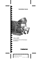
1
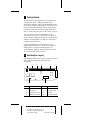
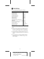
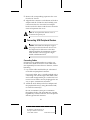
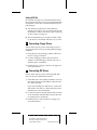
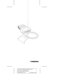
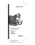
Installation Guide
AVA-2825
VL-to-Fast SCSI and VL-to-IDE Host Adapter
with SCSISelect
R
AA
AAAA
AA
AAAAAAAA
AAAAAAAA
AAAAAAAA
AAAAAAAA
AAAAAAAA
AAAAAAAA
AAAAAAAA
AAAAAAAA
AAAAAAAA
AAAAAAAA
AAAAAAAA
AAAAAAAA
AAAAAA
AA
AA
AA
AVA-2825 Installation Guide
AA
AA
AA
AA
AA
AA
Part
Number:
510612-00,
Rev
A
AA
AA
AA
AA
AA
AA
Print
Spec
Number:
492733-00
AA
AA
AA
AA
AA
AA
Current
Date:
6/8/94
ECN
Date:
6/14/94
AA
AA
AAAAAAAAAAAAAAAAAAAAAAAAAAAAAAAAAAAAAAAAAAAAAAAAAAAAAAA
AA
1 Getting Started
This Installation Guide explains how to install and
configure the AVA™-2825 host adapter. The
AVA-2825 combines support for both IDE and Fast
SCSI on one VL-Bus™ host adapter. This allows you
to benefit from the flexibility of Fast SCSI and the
fast data transfer rate of advanced IDE hard disk
drives, while using only one VL-Bus slot in your PC.
You can connect one or two IDE drives to the
AVA-2825. You can also connect up to seven SCSI
devices and two floppy disk drives. AVA-2825 host
adapters are designed for VL-Bus PCs with a 486™
or higher microprocessor.
To get the fastest data transfer rate from your
enhanced IDE disk drives, you need to install the
FLEXI-Driver™ software included with your
AVA-2825 host adapter. The FLEXI-Driver Installation Guide explains how to do this.
2 Host Adapter Layout
This diagram identifies the major AVA-2825 components. The following table describes each
component.
J1
J2
S1
J3
J4
J7
Location
J5
U12
Description
Location Description
J1
External LED Connector
J5
External SCSI Connector
J2
IDE Connector
J7
SCSI I/O Port Jumper
J3
Floppy Drive Connector
S1
Switch Block
J4
Internal SCSI Connector
U12
Host Adapter BIOS ROM
1
A
AAAA
AAAA
AAAA
A
AAAAAAAA
AAAAAAAA
AAAAAAAA
AAAAAAAA
AAAAAAAA
AAAAAAAA
AAAAAAAA
AAAAAAAA
AAAAAAAA
AAAAAAAA
AAAAAAAA
AAAAAA
AA
A
AA
AVA-2825 Installation Guide
A
AA
A
AA
A
AA
Part
Number:
510612-00,
Rev
A
A
AA
A
AA
A
AA
Print
Spec
Number:
492733-00
A
AA
A
AA
A
AA
Current
Date:
6/8/94
ECN
Date:
6/14/94
A
AA
A
AAAAAAAAAAAAAAAAAAAAAAAAAAAAAAAAAAAAAAAAAAAAAAAAAAAAAA
AA
3 Default Settings
The AVA-2825 default settings are as follows:
Parameter
Host Adapter Interrupt Channel
Host Adapter SCSI ID
SCSI Parity Checking
Host Adapter Termination
Host Adapter BIOS Address
Enable Sync Negotiation
Enable FAST SCSI
Enable Disconnection
System Boot (INT 19h) Controlled by Host
Adapter BIOS
Extended BIOS Translation for Drives >1 GByte
BIOS Support for Floptical Drives
SCSI I/O Port Address
IDE Data Transfer Speed
Floppy Drive Controller
1
Default Setting
IRQ 11
7
Enabled
Enabled
DC000h
Enabled
Enabled
Enabled
Enabled
Disabled
Disabled
340h–35Fh
3.3 MBytes/sec1
Enabled
This is the IDE Mode 0 data transfer rate. You can achieve higher IDE data transfer rates if you have an enhanced IDE disk drive and you install the FLEXI-Driver
software.
■
Many of these settings can be changed with the
SCSISelect configuration utility. See Configuring
the Host Adapter on page 8 for more information.
■
For information on changing the SCSI I/O port
address, see Changing the SCSI I/O Port Address on
page 4.
■
For information on changing the BIOS address
and the floppy drive controller setting, see the
table on page 3.
2
A
AAAA
AAAA
AAAA
A
AAAAAAAA
AAAAAAAA
AAAAAAAA
AAAAAAAA
AAAAAAAA
AAAAAAAA
AAAAAAAA
AAAAAAAA
AAAAAAAA
AAAAAAAA
AAAAAAAA
AAAAAA
AA
A
AA
AVA-2825 Installation Guide
A
AA
A
AA
A
AA
Part
Number:
510612-00,
Rev
A
A
AA
A
AA
A
AA
Print
Spec
Number:
492733-00
A
AA
A
AA
A
AA
Current
Date:
6/8/94
ECN
Date:
6/14/94
A
AA
A
AAAAAAAAAAAAAAAAAAAAAAAAAAAAAAAAAAAAAAAAAAAAAAAAAAAAAA
AA
4 Installing the Host Adapter
Changing Switches and Jumpers
This table shows all the possible settings of the
AVA-2825 switch block (s1). Default settings are
marked with an asterisk (*).
Floppy Drive Controller
sw1
Enabled*
On
Disabled
Off
IDE
sw2
Enabled*
Off
Disabled
On
BIOS Address
sw3
sw4
DC000h*
On
On
C8000h
Off
Off
CC000h
Off
On
D8000h
On
Off
If you need to change switch settings or the setting of
jumper J7, do it now before you install the host
adapter. Here are some possible reasons for changing
the settings:
Disabling the Floppy Controller
Only one floppy controller can be enabled in your
PC. If you leave the floppy drive cable attached to
the PC’s built-in floppy controller, turn sw1 Off to
disable the AVA-2825 floppy controller. If you connect the floppy drive cable to the host adapter, you
must disable the PC’s floppy controller. (The PC’s
floppy controller may be on a separate option card or
on the PC motherboard. See the PC documentation.)
Disabling the IDE Controller
Only one IDE controller can be enabled in your PC. If
you leave the IDE cable attached to the PC’s IDE controller, turn sw2 On to disable the AVA-2825 IDE controller. If you connect the IDE cable to the AVA-2825,
you must disable the PC’s IDE controller. (The IDE
controller may be on a separate option card or on the
PC motherboard. See the PC documentation.)
3
A
AAAA
AAAA
AAAA
A
AAAAAAAA
AAAAAAAA
AAAAAAAA
AAAAAAAA
AAAAAAAA
AAAAAAAA
AAAAAAAA
AAAAAAAA
AAAAAAAA
AAAAAAAA
AAAAAAAA
AAAAAA
AA
A
AA
AVA-2825 Installation Guide
A
AA
A
AA
A
AA
Part
Number:
510612-00,
Rev
A
A
AA
A
AA
A
AA
Print
Spec
Number:
492733-00
A
AA
A
AA
A
AA
Current
Date:
6/8/94
ECN
Date:
6/14/94
A
AA
A
AAAAAAAAAAAAAAAAAAAAAAAAAAAAAAAAAAAAAAAAAAAAAAAAAAAAAA
AA
Changing the SCSI I/O Port Address
The AVA-2825 SCSI I/O port address is set by jumper
block J7. The default port address is 340h-35Fh. You
can change the SCSI I/O port address to its alternate
setting of 140h-15Fh if it conflicts with another
option board in your PC. For example, if you install
two AVA-2825 host adapters in your PC, you must
change one host adapter’s SCSI I/O port to the alternate address.
To change the SCSI I/O port address, locate jumper
block J7 and remove the jumper shunt from pins 1
and 2 (the default setting). Then place the jumper
shunt on pins 2 and 3, as shown in this diagram:
Default I/O Port Address
1
2
Alternate I/O Port Address
3
1
2
3
Inserting the Host Adapter in a Slot
WARNING: Turn OFF and disconnect the
power to your PC and attached devices
before you remove the chassis cover. See the
PC documentation for instructions.
1 Remove the PC’s chassis cover to expose the
expansion slots and expansion slot covers.
2 Locate an unused VESA® local bus (VL-Bus)
expansion slot. VL-Bus slots are longer than ISA
slots, as shown in the diagram below:
Expansion
slot covers
VL-Bus slots
4
A
AAAA
AAAA
AAAA
A
AAAAAAAA
AAAAAAAA
AAAAAAAA
AAAAAAAA
AAAAAAAA
AAAAAAAA
AAAAAAAA
AAAAAAAA
AAAAAAAA
AAAAAAAA
AAAAAAAA
AAAAAA
AA
A
AA
AVA-2825 Installation Guide
A
AA
A
AA
A
AA
Part
Number:
510612-00,
Rev
A
A
AA
A
AA
A
AA
Print
Spec
Number:
492733-00
A
AA
A
AA
A
AA
Current
Date:
6/8/94
ECN
Date:
6/14/94
A
AA
A
AAAAAAAAAAAAAAAAAAAAAAAAAAAAAAAAAAAAAAAAAAAAAAAAAAAAAA
AA
3 Remove the corresponding expansion slot cover
from the PC chassis.
4 Align the bus connector on the bottom of the host
adapter with the VL-Bus slot and carefully press
it down into the slot. Secure the host adapter
bracket to the PC chassis with the screw from the
removed expansion slot cover.
Note: Do not replace the chassis cover or
reconnect the power yet!
5 Connecting SCSI Peripheral Devices
Caution: AVA-2825 host adapters support
only single-ended SCSI devices. Do not connect differential SCSI devices to this host
adapter. Read the documentation to determine whether a device supports singleended or differential SCSI.
Connecting Cables
SCSI devices are cabled together in a single, connected series called the SCSI bus. SCSI cables must
run sequentially from one device to the next, with no
branching.
1 Lay out the cables and find the pin-1 element of
each cable and peripheral connector.
On internal cables, pin 1 is usually marked with a
contrasting color on one edge of the ribbon cable,
and a small triangle marks pin 1 on the SCSI connector. External cables can only be plugged in one
way, so pin-1 orientation is automatic.
2 Attach the SCSI cable(s) to the host adapter and
the peripheral device(s), using the internal and/
or external connector(s).
Be sure to maintain correct pin-1 orientation
throughout the bus. The AVA-2825 uses a 50-pin
high-density external connector, and a 50-pin flat
ribbon-type internal connector.
5
A
AAAA
AAAA
AAAA
A
AAAAAAAA
AAAAAAAA
AAAAAAAA
AAAAAAAA
AAAAAAAA
AAAAAAAA
AAAAAAAA
AAAAAAAA
AAAAAAAA
AAAAAAAA
AAAAAAAA
AAAAAA
AA
A
AA
AVA-2825 Installation Guide
A
AA
A
AA
A
AA
Part
Number:
510612-00,
Rev
A
A
AA
A
AA
A
AA
Print
Spec
Number:
492733-00
A
AA
A
AA
A
AA
Current
Date:
6/8/94
ECN
Date:
6/14/94
A
AA
A
AAAAAAAAAAAAAAAAAAAAAAAAAAAAAAAAAAAAAAAAAAAAAAAAAAAAAA
AA
Terminating SCSI Devices
The last peripheral device at each end of the SCSI bus
must have a set of resistors called terminators
installed or enabled. Terminators must be removed
from, or disabled on, other devices in the middle of
the SCSI bus. The AVA-2825 and most SCSI peripherals have built-in terminators that can be enabled or
disabled.
Terminating the Host Adapter
Termination is enabled by default on AVA-2825 host
adapters. You must disable host adapter termination
if you attach SCSI devices to both the internal and
external SCSI connectors.
The table below lists possible SCSI device/host
adapter configurations.
Devices Connected to Host Adapter
Internal devices only
(host adapter at end of bus)
External devices only
(host adapter at end of bus)
Internal and external devices
(host adapter in middle of bus)
Host Adapter Termination
Enabled
Enabled
Disabled
AVA-2825 SCSI termination is controlled by the
SCSISelect program. If you need to disable host
adapter termination, first complete the physical
installation, then run SCSISelect and follow the directions in Configuring the Host Adapter on page 8.
Terminating Other SCSI Peripherals
1 Install/enable terminators on SCSI devices at the
ends of the SCSI bus (cable).
Check the manufacturer's documentation to
determine how to enable or disable termination
on SCSI disk drives and other SCSI peripheral
devices.
2 Remove/disable terminators on all devices in the
middle of the SCSI bus.
3 Be sure the SCSI cables are connected securely.
They may have been knocked loose if you
changed jumpers or switch settings on the
peripheral devices.
6
A
AAAA
AAAA
AAAA
A
AAAAAAAA
AAAAAAAA
AAAAAAAA
AAAAAAAA
AAAAAAAA
AAAAAAAA
AAAAAAAA
AAAAAAAA
AAAAAAAA
AAAAAAAA
AAAAAAAA
AAAAAA
AA
A
AA
AVA-2825 Installation Guide
A
AA
A
AA
A
AA
Part
Number:
510612-00,
Rev
A
A
AA
A
AA
A
AA
Print
Spec
Number:
492733-00
A
AA
A
AA
A
AA
Current
Date:
6/8/94
ECN
Date:
6/14/94
A
AA
A
AAAAAAAAAAAAAAAAAAAAAAAAAAAAAAAAAAAAAAAAAAAAAAAAAAAAAA
AA
Setting SCSI IDs
Be sure that each device on the AVA-2825 SCSI bus
has a different SCSI ID. See your SCSI peripheral documentation to learn how to determine the SCSI ID
and change it.
■
The default SCSI ID for the AVA-2825 host
adapter is SCSI ID 7. You can change the ID with
the SCSISelect utility, if necessary. (See Configuring
the Host Adapter on page 8.)
■
We recommend that you assign SCSI IDs 0 and 1
to the first two SCSI hard disk drives in your PC.
6 Connecting Floppy Drives
Follow these steps if you are connecting your PC’s
floppy disk drives to the AVA-2825 onboard floppy
controller:
1 Disconnect the 34-pin floppy ribbon cable from
the PC’s floppy controller.
2 Connect the floppy ribbon cable to the host
adapter ’s onboard floppy connector. Be sure to
maintain pin-1 orientation.
3 Disable the PC’s floppy controller. See page 3 for
more information.
7 Connecting IDE Drives
Follow these steps if you are connecting IDE disk
drives to the AVA-2825 IDE controller:
1 If the IDE drives are already installed in your PC,
disconnect the 40-pin IDE ribbon cable from the
PC’s IDE controller.
If you are installing new IDE drives, connect the
IDE cable to the drives, as described in the drive
manufacturer’s documentation.
2 Connect the end of the IDE ribbon cable securely
to the AVA-2825 onboard IDE connector. Be sure
to maintain pin-1 orientation.
3 Disable the PC’s IDE controller. See page 3 for
more information.
7
A
AAAA
AAAA
AAAA
A
AAAAAAAA
AAAAAAAA
AAAAAAAA
AAAAAAAA
AAAAAAAA
AAAAAAAA
AAAAAAAA
AAAAAAAA
AAAAAAAA
AAAAAAAA
AAAAAAAA
AAAAAA
AA
A
AA
AVA-2825 Installation Guide
A
AA
A
AA
A
AA
Part
Number:
510612-00,
Rev
A
A
AA
A
AA
A
AA
Print
Spec
Number:
492733-00
A
AA
A
AA
A
AA
Current
Date:
6/8/94
ECN
Date:
6/14/94
A
AA
A
AAAAAAAAAAAAAAAAAAAAAAAAAAAAAAAAAAAAAAAAAAAAAAAAAAAAAA
AA
Keep these points in mind when installing IDE
drives:
■
Your PC can recognize two physical IDE disk
drives when they are connected to the AVA-2825.
■
The first IDE drive must be set up as the master
drive (drive C) in CMOS setup, and the second
IDE drive (if any) as the slave drive.
■
If your PC has both IDE drives and SCSI drives, it
always boots from the IDE drive designated as
drive C.
■
IDE drives larger than 528 MBytes may require a
disk partitioning utility for use under DOS. The
utility is usually available from the drive manufacturer or the dealer.
■
You need to install FLEXI-Driver to attain the
highest data transfer rate from enhanced IDE
drives. See the FLEXI-Driver Installation Guide.
8 Reassembling and Starting the PC
1 Put the chassis cover back on the PC, following
the instructions in the PC documentation.
2 Be sure all power switches are OFF, then reconnect
power cables to the PC.
3 Turn ON the power for the PC and the peripheral
device(s).
When the PC boots, the host adapter BIOS sign-on
message appears on the screen. This message lists
installed SCSI devices and BIOS information. In
most cases your PC, host adapter, and SCSI peripherals are ready to use, and you do not need to run
the SCSISelect utility or change any switch settings.
9 Configuring the Host Adapter
Your AVA-2825 host adapter includes the SCSISelect
configuration utility. SCSISelect lets you change host
adapter settings such as parity checking and host
adapter SCSI ID without opening your PC or changing host adapter switches.
8
A
AAAA
AAAA
AAAA
A
AAAAAAAA
AAAAAAAA
AAAAAAAA
AAAAAAAA
AAAAAAAA
AAAAAAAA
AAAAAAAA
AAAAAAAA
AAAAAAAA
AAAAAAAA
AAAAAAAA
AAAAAA
AA
A
AA
AVA-2825 Installation Guide
A
AA
A
AA
A
AA
Part
Number:
510612-00,
Rev
A
A
AA
A
AA
A
AA
Print
Spec
Number:
492733-00
A
AA
A
AA
A
AA
Current
Date:
6/8/94
ECN
Date:
6/14/94
A
AA
A
AAAAAAAAAAAAAAAAAAAAAAAAAAAAAAAAAAAAAAAAAAAAAAAAAAAAAA
AA
To run SCSISelect, press Ctrl-A when you boot your
PC and the SCSISelect message appears.
Use the arrow (↑↓) and Enter keys to make selections. Press Esc at any time to return to the previous
menu. Press F6 to restore the original default settings.
To abandon changes made in the Configure/View
Host Adapter Settings menu, press Esc and select No
when asked if you want to save the changes.
Configure/View Host Adapter Settings
The SCSISelect Configuration screen displays these
options: Host Adapter Interrupt (IRQ) Channel, Host
Adapter SCSI ID, SCSI Parity Checking, and Host
Adapter SCSI Termination. Highlight an option and
press Enter to see a list of possible values.
Select SCSI Device Configuration to view a menu of
the following options: Enable Sync Negotiation,
Enable FAST SCSI, and Enable Disconnection. These
settings apply to all devices on the SCSI bus. You
must disable an option if one or more SCSI devices
do not support it.
Select Advanced Configuration Options to view a
menu of the following options: System Boot (Int 19h)
Controlled by Host Adapter BIOS, Extended BIOS
Translation for DOS Drives > 1 GByte, and BIOS
Support for Floptical Drives. Do not change these
options unless absolutely necessary.
SCSI Disk Utilities
When you select SCSI Disk Utilities from the Main
Menu, a list of installed SCSI devices appears. When
you select a device, the Utilities menu appears. Format Disk runs the Adaptec SCSI low-level format
utility. Verify Disk Media scans the selected disk
drive (or other disk device) for defects.
10 I/O Operating Environment Software
You can connect up to two hard disk drives to the
AVA-2825 without additional software. You need
additional software, such as Adaptec’s EZ-SCSI™
Lite, if you want to do the following:
■
Connect more than two hard disk drives
9
A
AAAA
AAAA
AAAA
A
AAAAAAAA
AAAAAAAA
AAAAAAAA
AAAAAAAA
AAAAAAAA
AAAAAAAA
AAAAAAAA
AAAAAAAA
AAAAAAAA
AAAAAAAA
AAAAAAAA
AAAAAA
AA
A
AA
AVA-2825 Installation Guide
A
AA
A
AA
A
AA
Part
Number:
510612-00,
Rev
A
A
AA
A
AA
A
AA
Print
Spec
Number:
492733-00
A
AA
A
AA
A
AA
Current
Date:
6/8/94
ECN
Date:
6/14/94
A
AA
A
AAAAAAAAAAAAAAAAAAAAAAAAAAAAAAAAAAAAAAAAAAAAAAAAAAAAAA
AA
■
Remove and insert magneto-optical and other
kinds of removable media while your PC is
running
■
Connect devices other than disk drives, such as
SCSI tape drives, CD-ROM drives, and scanners.
11 Troubleshooting Checklist
Check the following items first if you have a problem during installation:
■
Are all SCSI peripheral devices powered?
■
Are all SCSI bus cables and power cables properly
connected?
■
Does each SCSI device have a unique SCSI ID?
■
Are all devices on the SCSI bus terminated
properly?
PC Will Not Boot from a SCSI Disk Drive
If your PC has both SCSI and IDE disk drives, the
IDE disk drive is always the boot device. If the PC
has only SCSI disk drives, check the following:
1 Make sure your PC's CMOS setup is set to No
Drives Installed, which is required for SCSI host
adapters.
2 Make sure the SCSI ID of the boot hard disk is 0
and the boot partition is active. (The SCSI ID is
usually set with jumpers or switches on the
drive.)
3 If this does not solve the problem, back up all data
on the SCSI hard disk and perform a low-level
format with the SCSISelect Format Disk option.
4 Partition the disk. See the MS-DOS User’s Guide
for instructions.
12 Adaptec Customer Support
■
For information on software upgrades, new releases, technical
advice, and other topics, call Adaptec’s Electronic Bulletin
Board Service (BBS) 24 hours a day at 408-945-7727;
1200/2400/9600/14400 baud, 8 data bits, 1 stop bit, no parity.
■
For the latest online information about Adaptec products and
services, call the Interactive Fax Service 23 hours a day, 7 days a
week, at 408-957-7150.
10
A
AAAA
AAAA
AAAA
A
AAAAAAAA
AAAAAAAA
AAAAAAAA
AAAAAAAA
AAAAAAAA
AAAAAAAA
AAAAAAAA
AAAAAAAA
AAAAAAAA
AAAAAAAA
AAAAAAAA
AAAAAA
AA
A
AA
AVA-2825 Installation Guide
A
AA
A
AA
A
AA
Part
Number:
510612-00,
Rev
A
A
AA
A
AA
A
AA
Print
Spec
Number:
492733-00
A
AA
A
AA
A
AA
Current
Date:
6/8/94
ECN
Date:
6/14/94
A
AA
A
AAAAAAAAAAAAAAAAAAAAAAAAAAAAAAAAAAAAAAAAAAAAAAAAAAAAAA
AA
■
For technical assistance, call Adaptec’s Technical Support Hot
Line at 800-959-SCSI (7274), or 408-945-2550. M–Th: 6:00 a.m.–
5:00 p.m., F: 6:00 a.m.–3:00 p.m., Pacific Time.
■
To order Adaptec software and SCSI cables, call 800-442-SCSI
(7274), M–F: 6:00 a.m. to 5:00 p.m., Pacific Time. If you are calling from outside the U.S. and Canada, the number is
408-957-SCSI (7274).
■
To request additional documentation for Adaptec products,
call 800-934-2766, M–F: 5:00 a.m. to 6:00 p.m., Pacific Time.
FCC Compliance Statement
NOTE: This equipment has been tested and found to comply with the limits
for a Class B digital device, pursuant to Part 15 of the FCC rules. These limits are designed to provide reasonable protection against harmful interference in residential installations. This equipment generates, uses, and can
radiate radio frequency energy, and if not installed and used in accordance
with the instructions, may cause harmful interference to radio communications. However, there is no guarantee that interference will not occur in a
particular installation.
If this equipment does cause interference to radio or television equipment
reception, which can be determined by turning the equipment off and on,
the user is encouraged to try to correct the interference by one or more of the
following measures:
•
•
•
Reorient or relocate the receiving antenna
Move the equipment away from the receiver
Plug the equipment into an outlet on a circuit different from that to
which the receiver is powered
• If necessary, the user should consult the dealer or an experienced radio/
television technician for additional suggestions
CAUTION: Only equipment certified to comply with Class B (computer
input/output devices, terminals, printers, etc.) should be attached to this
equipment, and must have shielded interface cables.
Finally, any change or modifications to the equipment by the user not
expressly approved by the grantee or manufacturer could void the user's
authority to operate such equipment.
Each host adapter is equipped with an FCC compliance label which shows
only the FCC Identification number. The full text of the associated label
follows:
This device complies with part 15 of the FCC rules. Operation is
subject to the following two conditions: (1) this device may not
cause harmful interference and (2) this device must accept any interference received, including interference that may cause undesired
operation.
Adaptec, Inc.
691 South Milpitas Blvd.
Milpitas, California 95035
Copyright © 1994 Adaptec, Inc. All rights reserved. Adaptec and
the Adaptec logo are registered trademarks of Adaptec, Inc. AVA,
FLEXI-Driver, EZ-SCSI and SCSISelect are trademarks, of
Adaptec, Inc. VL-Bus is a trademark of the Video Electronics Standards Association. 486 is a trademark of Intel Corporation.
Printed in Singapore
Stock No.: 510612-00, Rev A KL 6/94
Information subject to change without notice.
11
A
AAAA
AAAA
AAAA
A
AAAAAAAA
AAAAAAAA
AAAAAAAA
AAAAAAAA
AAAAAAAA
AAAAAAAA
AAAAAAAA
AAAAAAAA
AAAAAAAA
AAAAAAAA
AAAAAAAA
AAAAAA
AA
A
AA
AVA-2825 Installation Guide
A
AA
A
AA
A
AA
Part
Number:
510612-00,
Rev
A
A
AA
A
AA
A
AA
Print
Spec
Number:
492733-00
A
AA
A
AA
A
AA
Current
Date:
6/8/94
ECN
Date:
6/14/94
A
AA
A
AAAAAAAAAAAAAAAAAAAAAAAAAAAAAAAAAAAAAAAAAAAAAAAAAAAAAA
AA