1
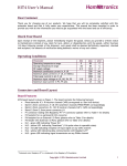
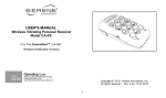
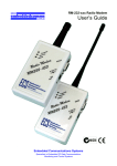
2Qd=_^
Battery Monitor for R/C Models
Introduction
BATMON is a radically different battery monitoring system. It uses a sophisticated battery fuel gauge
technology and performs mAH (milliamp hour) capacity measurements by carefully monitoring the
actual current that goes in and out of your R/C system’s battery pack.
Traditionally, NiCD and NiMH battery capacity levels are merely estimated by measuring their loaded
voltages. Unfortunately, this technique attempts to use a
shallow voltage curve that is very susceptible to
changes in temperature. In addition, the battery’s
unique characteristics, which often change with age,
can affect the voltage measuring technique. Users of
voltage monitoring systems must accept that they will
only be warned when the battery is almost fully
discharged (below 30% remaining capacity), as
indicated by their go/no-go nature.
Figure 1
But, with BATMON you can review your R/C battery’s
remaining capacity as either (1) 0% to 100% capacity or
(2) actual remaining mAH. Both 4.8V and 6.0V (NiCD or NiMH) batteries are supported, with cell
capacities from 400 mAH to 2400 mAH. All features and options are programmed using a single
pushbutton switch.
Besides battery gauging, BATMON also provides battery voltage monitoring. This additional feature
acts as a safeguard against R/C system failures. It issues a warning if your battery pack is defective
(weak/shorted cell) or your airborne equipment has an intermittent cable/switch connection. It
measures two important voltages too -- at the battery pack and any R/C servo connector.
Battery Status Display and LED
Battery status is reported using a single character digital display and a high intensity LED. The
readout shows alphanumeric messages, such as status text or battery capacity values. Multi
character messages and numbers are sequenced in a method that closely resembles spelling out a
word. This method is easy to use.
The digital display can show the actual remaining battery CAPACITY or LEVEL. A pushbutton
switch is used to toggle between the two modes. Battery CAPACITY is shown as a one to four digit
number, which is scaled as mAH. Battery LEVEL is a single digit value and can range from zero to
nine. This corresponds to a 0% to 100% battery level in 10% increments. The preferred display mode
is the latter since it shows the battery’s condition as a single digit (0-9, and F).
(c) 2000-2002 by T. Black. All rights reserved.
Page 1
June-17-2002 Rev A9
During the LEVEL mode, the display’s decimal dot will blink to identify that the display is showing the
battery level. The values have the following meaning (see Table 1):
LEVEL
DESCRIPTION
0
00 - 09% remaining capacity, Empty.
1
10 - 19% remaining capacity.
2
20 - 29% remaining capacity.
3
30 - 39% remaining capacity.
4
40 - 49% remaining capacity.
5
50 - 59% remaining capacity, Half Full.
6
60 - 69% remaining capacity.
7
70 - 79% remaining capacity.
8
80 - 89% remaining capacity.
9
90 - 99% remaining capacity.
F
100% FULL.
TABLE 1
To conserve battery power, the display will blank itself after a few seconds. However, the level mode
value will flash every few seconds. Also, the display can be restored by pressing the pushbutton
switch (each press will turn it on for few seconds). If you wish, you can set it to stay on full time. The
blanking feature will help reduce power consumption and is the recommended setting during normal
use.
If you are in the Fuel Level mode and the display has shut off, it will momentarily flash the level value
every four seconds. So button pressing is usually not necessary.
BATMON’s high intensity blue LED can be seen in daylight and from long distance. It provides the
overall battery status by a solid or blinking pattern. The following table describes the LED operation
(see Table 2):
BLUE LED
OFF
STEADY
DESCRIPTION OF BATTERY CONDITION
Receiver Power is off.
Battery level is OK.
FAST SINGLE
WINK
Battery level is below 30%. Time to recharge.
FAST DOUBLE
WINK
Battery level is dangerously low, intermittent connection, or system error.
A condition exists that requires your immediate attention.
TABLE 2
(c) 2000-2002 by T. Black. All rights reserved.
Page 2
June-17-2002 Rev A9
Installation
You can install BATMON in your R/C model using its three servo style connectors. Mount it in a
location that allows you to see the bright blue LED while you are flying (or driving) your model.
Essentially you will place it between the battery pack and the receiver using two of the cables. A third
cable is connected to any R/C channel on the receiver. Please follow these simple instructions to
connect the cables (refer to Table 3 and Figure 2).
LABEL
CABLE CONNECTION DESCRIPTION
BAT
Connect this cable directly to the battery.
RX
Connect this cable to your receiver’s on/off switch.
AUX
Connect this cable to any receiver channel. For best results, use an empty
channel or one with a lightly loaded servo such as the throttle (just use a servo
“Y” adapter).
TABLE 3
We recommend that you charge the battery pack prior to connecting it to BATMON. This will ensure
that the capacity gauging measurements are automatically synchronized to your battery.
Figure 2
(c) 2000-2002 by T. Black. All rights reserved.
Page 3
June-17-2002 Rev A9
Set-Up Configuration / System Programming
The first time you use BATMON it will default to the factory configured parameters. The defaults are
listed in Table 4:
PARAMETER
DEFAULT SETTING
Cell Count
4 (four cells, 4.8 Volts)
Cell Capacity
6 (600 mAH)
Display Mode
d (on Demand -- pushbutton press)
Battery Level / Remaining Capacity
9 / 596
TABLE 4
You can change the default values using BATMON ’s special PROGRAM mode. This feature is enabled
as follows:
1.
2.
3.
4.
Turn on your R/C receiver’s power switch. Wait for BATMON’s digital display to appear.
Turn off the R/C power switch and then quickly press and hold the pushbutton switch.
Immediately turn the R/C switch back on (within three seconds).
Release the pushbutton switch. Confirm that the display shows a flashing “P.”
Note: At this point you can exit the PROGRAM mode by pressing the pushbutton switch or by turning off
the R/C receiver’s power for more than four seconds.
There are several menu items that you can select during the PROGRAM mode. Navigating them is
performed by toggling R/C power off, then back on again (within three seconds). Each on-off-on
action will move you to the next menu item. The pushbutton switch on BATMON is used to change the
item in the selected menu.
(c) 2000-2002 by T. Black. All rights reserved.
Page 4
June-17-2002 Rev A9
Let us review these two switch operations again:
R/C (RECEIVER) SLIDE SWITCH: Move to the next menu selection.
BATMON ’S PUSHBUTTON SWITCH: Enter/change value.
The seven PROGRAM modes are defined as follows:
Cx, Current Meter
The displayed value is the actual current used by the R/C
equipment. The measured value can be displayed at two
different speeds, which can be toggled by pressing the push
switch. The slow sample times are best suited for static loads.
However, with some effort, you can witness peak servo current
draw if you continuously move the transmitter sticks around.
FUL, Full Battery Level
Pressing the pushbutton will set the battery level to full charge,
despite the pack’s true state.
CLR, Clear Battery Level (Empty)
Pressing the pushbutton will reset the battery level to 0%
(empty), despite the pack’s true state.
BL-x, Display Blanking
Select “D” for on-demand display or “F” for full time display.
CAPx, Cell Capacity
Divide your battery’s labeled or measured mAH capacity by 100
and enter the nearest whole value by pressing the pushbutton
(increments value). For example, enter 650 mAH as “6" and
1400 mAH as “14.” Although the possible values range from 1
to 25 (100 mAH to 2500 mAH), for best accuracy you should
restrict your entries to 4 - 24.
CELx, Cell Count
Select “4" for four cell (4.8V ) packs and “5" for five cell ( 6.0V)
packs.
END, Exit
You can exit the Program mode and store your new settings by
pressing the push switch or turning off R/C power for about five
seconds.
Figure 3
(c) 2000-2002 by T. Black. All rights reserved.
Page 5
June-17-2002 Rev A9
Status and Error Messages
There are several status and error messages that can be displayed. Please consult Table 5 if any
messages appear:
MESSAGE
r
DEFINITION
System RESET due to lost battery voltage.
chg
Battery appears to be CHARGED.
F
Battery at FULL capacity (100%).
U1
Battery voltage is low.
U2
Receiver/Servo voltage is VERY low or has been lost.
U3
Receiver/Servo voltage is low.
oc
Over-Current, load exceeded 2.5 Amps.
E1
System Error: Stored parameters are incorrect.
E2
System Error: Microprocessor can’t communicate with
battery sensor.
E3
System Error: E2Prom based user parameters not found.
Auto-initialization has restored factory default settings.
Note: This message will occur the very first time power is applied
to a newly built board because the E2Prom is blank. It should
NOT occur on subsequent use if operating correctly.
TABLE 5
Generally, pressing the pushbutton switch will cancel the messages. If doing so clears codes U1
through U3, then you may have a (1) weak/bad battery, (2) intermittent connection, or (3) a servo
that draws excessive current. Error OC indicates that the peak charge or discharge levels are
extremely high and should be investigated. If these error codes persist, you can press and hold the
pushbutton switch to review the battery’s CAPACITY or LEVEL.
Please be aware that you can simulate a dangerously low battery or intermittent connection by
turning the R/C power off, then immediately back on. To avoid this error just keep the power switch
off for more than four seconds before turning it back on. You can also press the pushbutton switch to
clear the message.
Error codes E1 through E3 may indicate that you have a problem with your BATMON system. These
errors may occur if the battery voltage is extremely low, so please try recharging your battery pack. If
the “E” messages persists then factory service may be required.
Battery Recharging Instructions
BATMON knows the difference between discharge and charge currents. In fact, during the recharging
period the reported capacity level will actually increase. However, the charge efficiency of your
particular battery can vary with recharge currents, temperature, and cell characteristics. Rather than
burden you with complicated configuration settings, we have taken a more relaxed approach to the
recharge cycle.
To partially accommodate the battery’s recharge efficiency, BATMON approximates it by periodically
applying a 20% mAH reduction (80% charge efficiency). This value is a good compromise for typical
NiCD and NiMH batteries. The reduction occurs automatically every thirty minutes during a
continuous charge cycle.
(c) 2000-2002 by T. Black. All rights reserved.
Page 6
June-17-2002 Rev A9
Generally you will use a C/10 charge rate for fourteen or fifteen hours. Higher charge rates, up to C/1
can be used too, even if they charge the battery before the automatic reduction update period.
BATMON is designed to limit the accumulated charge current -- it stops counting current when the
rated capacity size of the battery is met. This technique ensures that the reported battery capacity
remains synchronized to the charge cycle.
For best results you must continue to follow the recharging instructions provided by your radio system
or after-market battery charger. Do NOT use BATMON’s “Chg” (charged) or “F” messages as an
indication of a completed charge cycle.
NiCD/NiMH Self-Discharge Monitoring
An interesting characteristic of NiCD and NiMH batteries is that they lose their charge while in
storage (sitting idle). This undesirable condition is referred to as self-discharge. It is one of the
reasons that R/C modelers are instructed to recharge their batteries before each use.
The actual amount of self-discharge depends on a number of factors including battery type, age,
chemistry, and temperature. Generally a NiCD cell will lose about 20% of the rated capacity in the
first month and modern NiMH types will lose a similar amount.
To help you monitor for this issue, BATMON automatically reduces the reported battery capacity to
track the self-discharge condition. The reduction occurs once per day while your model’s R/C system
is turned off.
BATMON’s self-discharge calculations attempt to approximate an average cell’s behavior at nominal
temperature. A normalized method is used to keep user interaction and basic operation as simple as
possible. The reduction is a practical estimate and it works quite well for all R/C applications. But
regardless of the reported capacity value, always follow the advice of your radio maker and charge
your battery before each use (per their instructions).
Status Interface
The 3-pin J5 header provides status signals for the common battery states. The signals are
CMOS/TTL compatible and are defined in Table 6.
SIGNAL NAME
LOGIC HIGH
LOGIC LOW
J5-1, BATLOW
Battery low warning
Battery above 30%
J5-2, BATOK
Battery is OK
Battery problem warning
J5-3, BATCHRG
Battery is 100% fully charged
TABLE 6
Battery below 100%
What you do with these signals is up to you. They may be interfaced to other electronic gear
(telemetry, video OSD, audio annunciators, lights, etc.). Please be aware that they can only sink or
source about 20mA.
(c) 2000-2002 by T. Black. All rights reserved.
Page 7
June-17-2002 Rev A9
System Calibration
BATMON requires calibration after assembly. This is a simple push-button process. The calibration
feature is totally digital and the parameters that are measured are stored in memory. Once calibrated,
you will probably never need to repeat these steps.
To prevent an accidental attempt, enabling the calibration feature must be closely followed or it will
be ignored. To calibrate your unit please follow these instructions:
1)
Turn On the R/C power switch and wait at least three seconds. Verify that the blue LED and
display is on.
2)
Now turn Off the R/C power switch (verify that the LED and display are off). Within ten
seconds, press and hold the pushbutton switch. Leave R/C power Off!
3)
After five seconds, the display’s decimal dot will come on. Immediately release the pushbutton
switch (within two seconds of the dot). Do not continue pressing the button!
4)
The calibration will occur automatically and will take less than one second. If successful, a “C”
will be shown for a moment. If an error occurs the calibration will be aborted and a “E” will be
shown.
(c) 2000-2002 by T. Black. All rights reserved.
Page 8
June-17-2002 Rev A9
Specifications
Parameter
Min
TYP
Max
Units
Supply Voltage
4.2
4.8/6.0
7.5
VDC
Supply Current, idle (See Note 1)
150
180
195
uA
Supply Current: LED Off, Disp Off
1.2
1.7
2.5
mA
Supply Current: LED On, Disp Off
10
14
18
mA
Supply Current, LED On, Disp On
15
45
55
mA
Allowed Load Current (See Note 2)
3000
mA
Accumulated Battery Capacity
2500
mAH
9.8
mAH
Capacity Accuracy
5
%
“Fuel” Level Resolution
10
% of mAH
“Fuel” Level Accuracy
5
%
4.9
mA
5
%
Capacity Resolution
Current Meter Resolution
Current Meter Accuracy (See Note 3)
U1 Battery Low Voltage Warning
1.12
1.14
1.16
VDC per Cell
U2 Aux Very Low Voltage Warning
1.08
1.10
1.12
VDC per Cell
U3 Aux Low Voltage Warning
1.12
1.14
1.16
VDC per Cell
OC, Over Current Warning
2400
2500
2600
mA
Note 1. Idle mode occurs within 20 seconds after R/C receiver’s switch is turned off and supply voltage > minimum.
Note 2. The rated maximum current draw is offered as technical information and is not recommended for normal use.
Note 3. Current accuracy is constrained by the resolution specification.
Updated BATMON project files and email contact information is available at:
http://www.digitalproductsco.com/batmon/
(c) 2000-2002, all rights reserved
(c) 2000-2002 by T. Black. All rights reserved.
Page 9
June-17-2002 Rev A9