1
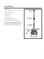
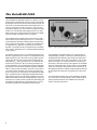
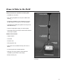
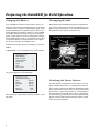
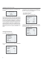
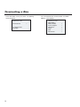
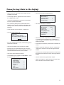
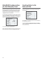
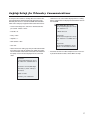
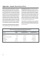
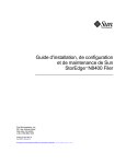
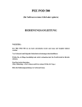
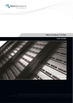
United States
Department of
Agriculture
Forest Service
Technology &
Development
Program
DataRAM 2000
Particulate Monitor
Forest Service User’s Guide
2500 Watershed
April 2002
0225-2803-MTDC
Mary Ann Davies
Project Leader
USDA Forest Service
Technology and Development Program
Missoula, MT
TE82F55—Watershed, Soil, and Air
Technical Services
April 2002
The Forest Service, United States Department of Agriculture (USDA), has developed this
information for the guidance of its employees, its contractors, and its cooperating Federal and
State agencies, and is not responsible for the interpretation or use of this information by anyone
except its own employees. The use of trade, firm, or corporation names in this document is for
the information and convenience of the reader, and does not constitute an endorsement by the
Department of any product or service to the exclusion of others that may be suitable.
The U.S. Department of Agriculture (USDA) prohibits discrimination in all its programs and
activities on the basis of race, color, national origin, sex, religion, age, disability, political beliefs,
sexual orientation, or marital or family status. (Not all prohibited bases apply to all programs.)
Persons with disabilities who require alternative means for communication of program
information (Braille, large print, audiotape, etc.) should contact USDA’s TARGET Center at
(202) 720-2600 (voice and TDD). To file a complaint of discrimination, write USDA, Director,
Office of Civil Rights, Room 326-W, Whitten Building, 1400 Independence Avenue, SW, Washington, D.C. 20250–9410, or call (202) 720-5964 (voice and TDD). USDA is an equal opportunity
provider and employer.
Contents
Introduction _____________________________________ 1
The DataRAM 2000 _______________________________ 2
Items to Take to the Field __________________________ 3
Preparing the DataRAM for Field Operation ___________ 4
Charging the Battery ____________________________________ 4
Uncapping the Inlet _____________________________________ 4
Switching the Power Selector ______________________________ 4
Configuring the Instrument at Your Office ____________ 5
Setting the Date and Time ________________________________
Zeroing the DataRAM ____________________________________
Running the Span Check _________________________________
Setting Parameters ______________________________________
5
5
5
6
Setting Up the Laptop at Your Office _________________ 7
Disabling the Infrared Port ________________________________ 7
Setting Up a Hyperterminal Connection ______________________ 7
Siting the DataRAM _______________________________ 8
Logging Data ____________________________________ 9
Terminating a Run _______________________________ 10
Transferring Data to the Laptop ____________________ 11
Deleting Data from the DataRAM ___________________ 12
Transferring Data Into Excel_______________________ 12
Remote Satellite Telemetry System for the DataRAM __ 13
Telemetry Equipment ____________________________ 13
Data Retrieval From the Internet ___________________ 14
DataRAM and Remote Telemetry Setup _____________ 15
DataRAM Configuration for the Telemetry Unit _______ 16
Sending Data to the Internet Site ___________________ 16
Laptop Setup for Telemetry Communications ________ 17
Appendix—Smoke From Forest Fires _______________ 18
ii
Introduction
This guide explains:
• Where to site the DataRAM 2000 to collect local smoke data
Omnidirectional
sampling inlet
model DR-OSI
• How to assemble the instrument
• How to start a run
• How to stop a run
• How to set up the laptop
• How to download the data into the laptop
Inline impactor head
model DR-PM10/2.5
• How to transfer the data into an Excel spreadsheet.
The guide will also help you set up the remote satellite
telemetry system, assemble and configure the DataRAM for
proper communication with the telemetry system, and verify
that the system is sending data before you leave the site.
Temperature
conditioning heater
model DR-TCH
Inline heater
power cable
DataRAM 2000
particulate
monitor
The DataRAM 2000 instrument and accessories.
1
The DataRAM 2000
The DataRAM 2000 particulate monitor is a compact, self-contained instrument that internally estimates the mass concentration
of particulate in the air from the measured scattering of light. The
instrument can measure particulate concentrations from 0.1 to
400,000 micrograms per cubic meter of air. The instrument
continuously displays the current and time-weighted average
(TWA) mass concentration while logging up to 10,000 data
points. Data can be transferred from the instrument to a laptop
computer through the laptop’s RS-232 serial port.
The DataRAM can be configured with either a PM2.5 or PM10
inlet head to prevent particles larger than 2.5 or 10 micrometers,
respectively, from entering the optical chamber where particulate is measured. The DR-PM10/2.5 model of the DataRAM 2000
is shipped for PM10 operation. To convert the inlet to PM2.5
operation, a conversion nozzle is threaded onto the central flow
tube. The PM2.5 micrometer inlet is recommended for monitoring
smoke (figure 1).
The impactor surface consists of a 25-millimeter-diameter glass
fiber filter supported by one section of a standard plastic filter
holder. Replace the glass filter when it has any brown or black
soiled spots. Refer to the instruction note provided with the
model DR-PM10/2.5 inline impactor head. A 37-millimeter filter
located in the instrument’s base can collect particulates for
custom calibrations, or for analyzing the chemical composition
of particulates. An inline heater should be installed for conditions
above 70 percent relative humidity. The inline heater requires
120-volt line power. Humidity of 70 percent and above may
occur at any time in the early morning, even during low-humidity
days. The tubular heater is designed to evaporate liquid water
from airborne particles or to eliminate fog droplets. The DataRAM is powered by an internal rechargeable battery or by an
external dc or ac power source. The Missoula Technology and
Development Center (MTDC) recommends having 120-volt
line power available for the DataRAM and inline heater.
2
Inline impactor head model DR-PM10/2.5
PM2.5 conversion nozzle
25-millimeter-diameter
glass fiber filter holder
Figure 1—Inline impactor head with the PM2.5 nozzle installed.
The DataRAM is not approved by the U. S. Environmental
Protection Agency (EPA) as a reference method sampler. The
DataRAM instrument provides general trends of smoke particulate concentration. These data can enable the user to verify
whether the impacts of smoke particulate are increasing or
decreasing. A correction factor of 0.48 is applied to the DataRAM
based on experimental data. In other words, if the DataRAM
shows 100 micrograms of particulate per cubic meter of air, an
EPA-approved reference method sampler would be expected
to show about 48 micrograms of particulate per cubic meter
of air.
The center published Real-Time Smoke Particulate Sampling:
Fire Storm 2000 (0125-2832-MTDC) which explains EPA airquality standards and how the DataRAM 2000 correction
factor of 0.48 was determined.
Items to Take to the Field
These accessories are required for monitoring PM2.5:
• DataRAM 2000 instrument
Omnidirectional sampling
inlet model DR-OSI
• PM2.5 inlet head (optional accessory for the MIE model
DR-PM10/2.5)
• Temperature conditioning heater (optional accessory for
the MIE model DR-TCH, figure 2) (120-volt line power)
• Omnidirectional sampling inlet (optional accessory for the
MIE model DR-OSI)
Inline impactor head
model DR-PM10/2.5
• Universal charger/power supply (120-volt line power)
• Serial output cable (gray nine-pin communication cable for
connecting to a laptop)
Additional items needed:
• Laptop computer
Temperature
conditioning heater
model DR-TCH
• Small table
• Extension cord
• Four-plug power strip
DataRAM 2000
particulate
monitor
• Rain shelter cover (available from Mary Ann Davies at
MTDC)
• 120-volt line power for extended operation
• Cable lock for security (wrap the cable around the
DataRAM’s leg and another secure object)
• Remote telemetry unit
Figure 2—The DataRAM with all three ambient monitoring
accessories.
3
Preparing the DataRAM for Field Operation
Charging the Battery
Uncapping the Inlet
If the DataRAM has not been used for about 3 months, the
battery will need to be fully recharged. Plug it into a 120-volt line
for about 12 hours to restore it to full operating capacity. A new
and fully charged battery can provide at least 20 hours of continuous operation at temperatures above 60 °F. The DataRAM
can operate continuously using its universal charger/power
supply—simply attach the universal charger/power supply to
the DataRAM and plug it into a 120-volt power source. Never
let the internal battery run completely down. If this happens,
the unit may need to be sent to MIE for repair.
Before operating the DataRAM, the protective Swagelok stem
cap must be removed from the air inlet and stored on the gray
pod on the back panel (figure 3). The DataRAM should never
be operated with the stem cap covering the inlet.
To determine the charge capacity of the battery, turn the DataRAM on.
Inlet with protective Swagelok cap
Universal
charger/
power
supply
Span Check
calibrator knob
Power selector
switch
At ‘MAIN MENU 1’, press the button next to ‘System Diagnos’.
14:02:19 01 Oct
MAIN MENU 1
RUN (zeroed?)
System Diagnos
Parameters
Purge
Zero
Next Screen
>
>
>
>
>
>
RS-232 cable
to laptop
Store Swagelok
on this keeper
RS-232 serial output cable
(gray nine-pin communication cable)
Figure 3—Back-panel view of the DataRAM.
The system diagnostic screen will display.
14:02:19 01 Oct
SYSTEM DIAGNOST
Filter
Normal
Battery
Normal
Backgrnd
Normal
Flow
Normal
BatChrg
12345
Flowrate2.0
Lpm
When the battery is fully charged, ‘BatChrg’ numbers ‘12345’
will display.
4
Switching the Power Selector
The three-position, locking power-selector switch on the rear
panel should be switched ‘OFF (0)’ (middle position) when the
unit is stored or transported. To enable the DataRAM to operate
with its internal battery or the charger, the power selector switch
must be ‘ON (1)’ (up position). The ‘EXT (1)’ (down position) is
used only when an external dc source (such as solar power or
an external battery) is powering the unit. To change the locking
position, pull the handle out while moving the power selector
switch to the desired position.
Configuring the Instrument at Your Office
First, remove the Swagelok protective cap from the air inlet
on the top of the DataRAM. The DataRAM 2000 internal pump
turns on at powerup and continues to run during setup. The
Swagelok cap should be stored on the keeper pod on the back
of the unit.
Select ‘Set Date, Time’ by pressing the button beside that
selection. The first digit on the hour will flash. Use the ‘v’ or ‘^’
arrow buttons to change the numerals. Use the ‘>’ or ‘<’ arrow
buttons to move across the date and time numerals. When the
date and time are correct, press the ‘EXIT’ button to set them.
Push the ‘ON’ button on the front panel to power up the
DataRAM.
Zeroing the DataRAM
Setting the Date and Time
The ‘MAIN MENU 1’ screen (figure 4) automatically displays
at powerup.
Press the ‘EXIT’ button once more or ‘Last Screen’ to return
to ‘MAIN MENU 1’.
14:02:19 01 Oct
MAIN MENU 1
RUN (zeroed?)
System Diagnos
Parameters
Purge
Zero
Next Screen
>
>
>
>
>
>
With ‘MAIN MENU 1’ displayed, press the button next to ‘Zero’.
The DataRAM will perform a zero and span check to ensure
that the optical device is clean. While the DataRAM is zeroing,
the screen will flash ‘ZEROING’ and ‘WAIT’.
14:02:19 01 Oct
ZEROING
WAIT
Figure 4—The DataRAM’s main menu screen.
14:01:19 01 Oct
MAIN MENU 1
RUN (zeroed?)
System Diagnos
Parameters
Purge
Zero
Next Screen
>
>
>
>
>
>
After pressing ‘Next Screen’ on ‘MAIN MENU 1’, ‘MAIN MENU
2’ will display.
14:02:19 01 Oct
MAIN MENU 2
DumpDataRS232
Set Date, Time
ScrollDataLog
Last Screen
Running the Span Check
After zeroing is complete, the DataRAM needs to perform a
span check.
14:02:19 01 Oct
ZERO COMPLETE
Span Check
>
>
>
>
>
5
Configuring the Instrument at Your Office
Press the button next to ‘Span Check’. The following screen
will display.
If the CalFactor is not set to 48 percent, press the button next
to ‘CalFactor’. Use ‘^’ or ‘v’ to increase or decrease the number
and ‘<’ or ‘>’ to move across the number.
14:02:19 01 Oct
• Set ‘CalFactor’ to 48 percent.
• Set ‘Flowrate’ to 2.0 Lpm.
• ‘Auto Zero’ and ‘Alarm’ can be set to ‘OFF’.
insert
calibrator
At the back of the instrument is a black ‘Span Check’ knob with
arrows showing how to rotate it ‘IN’ or ‘OUT’. While facing the
screen, turn the ‘Span Check’ knob counterclockwise or ‘IN’ all
the way until it stops. When the Span Check is complete, the
screen will display ‘RETRACT CALIBRATOR’. On the bottom of
the screen, the ‘Calibr Diff’ should range between plus or minus
10%. If the ‘Calibr Diff’ is more than ±10%, repeat the ‘Zero’
and ‘Span Check’ again. If the value is still outside the ±10%
range, contact MIE, Inc. or MTDC. Turn the ‘Span Check’ knob
clockwise when facing the screen or ‘OUT’ all the way until it
stops. When the Span Check is complete, ‘MAIN MENU 1’ will
display.
14:02:19 01 Oct
PARAMETERS 2
Auto Zero:
Alarm:
CalFactor
Flowrate
If any parameters have been changed, press the ‘EXIT’ button
to store the new settings. Press ‘EXIT’ one more time to go back
to the ‘PARAMETERS 1’ screen.
14:02:19 01 Oct
PARAMETERS 1
AvgTime:
LogData:
Setting Parameters
ClearData:
Tag#:
Next Screen:
Press the button beside ‘Parameters’.
14:02:19 01 Oct
MAIN MENU 1
RUN (zeroed?)
System Diagnos
Parameters
Purge
Zero
Next Screen
>
>
>
>
>
>
Press the button beside ‘Next Screen’ to display ‘PARAMETERS
1’ menu.
14:02:19 01 Oct
PARAMETERS 1
AvgTime:
LogData:
ClearData
Tag#
Next Screen
6
10sec>
OFF>
>
>
1>
>
OFF>
>
OFF>
>
048%>
2.0Lpm>
10sec>
OFF>
>
>
1>
>
Setting Up the Laptop at Your Office
Before transferring logged data to a laptop, you need to set
up the laptop to receive the data.
• Data bits > 8.
• Parity > none.
• Stop bits > 1.
Disabling the Infrared Port
• Flow control > Xon/Xoff.
• Click ‘OK’.
To disable the infrared (IR) port on a newer IBM ThinkPad:
• Click on ‘Start’ (at the bottom left corner on the startup
screen).
• Double click on ‘Settings > Control Panel > Infrared’.
• The ‘Infrared’ box is displayed.
• Click on the page tab for ‘Options’. Uncheck the box ‘Enable
infrared communication’.
• The HyperTerminal window will open and show ‘Connected’
on the button at the bottom of the window.
• Leaving the HyperTerminal window open, click on ‘File’ at
the top of the window. Choose ‘Properties’. The ‘Name you
gave to identify your HyperTerminal’ properties box will
appear.
• Click on the ‘Settings’ tab.
• Check the ‘Terminal keys’ box.
• The other two boxes on the ‘Preferences’ page can be left
checked. Click ‘OK’.
• Close the control panel by clicking on the ‘X’ at the upper
right corner of the window.
• Click on the arrow next to ‘Emulation’ and choose ‘TTY’.
• The ‘Backscroll buffer lines’ box needs to be set to 500. Type
‘500’ or use the increase/decrease arrows to get to 500.
• Click on the page tab for ‘Preferences’. Check the box
‘Display infrared icon on task bar’. This places an infrared
icon with a slash across it at the bottom right of the startup
screen to verify that the infrared port is disabled.
• Click on the ‘ASCII Setup’ box.
• Check ‘Send line ends with line feed’.
• Check ‘Echo typed characters locally’.
• Check ‘Append line feeds to incoming line ends’.
Setting Up a Hyperterminal Connection
• Check ‘Wrap lines that exceed terminal width’.
• Click ‘OK’.
• Click on ‘Start’ (at the bottom left corner on the startup
screen).
• Click ‘OK’ on the ‘Properties’ page.
• The ‘HyperTerminal’ screen will display.
• On the button bar at the top of the HyperTerminal window,
click on the phone that has the receiver off. This will disconnect
communications for now. The bottom bar in the HyperTerminal
will display ‘Disconnected’.
• The ‘Connection Description’ box will appear. Type in a
name and pick an icon to identify your HyperTerminal.
• On the menu bar at the top of the HyperTerminal window,
click ‘File > Save As’.
• Click ‘OK’.
• Click on the down arrow on the right side of the ‘Save In:’
dialog box and choose ‘Desktop’.
• Click on ‘Programs > Accessories > HyperTerminal (single
click) > Hypertm.exe’ (double click).
• The ‘Phone number’ box will appear. At the bottom of this
box, click on the arrow beside ‘Connect Using’ and choose
‘Direct to Com 1’. Click ‘OK’.
• The ‘Com 1 Properties with Port Settings’ box will appear.
Click on the arrow next to ‘Bits per second’ and choose
‘9600’.
• The name you chose for your HyperTerminal will appear in
the ‘File name:’ dialog box.
• Click ‘Save’.
• Close the HyperTerminal window by clicking ‘File > Close’
on the menu bar at the top.
7
Siting the DataRAM
The DataRAM should be placed at least 3 feet off the ground
and away from obstructions (such as trees or buildings) that
may influence airflow. It should be in an area where it will not
be influenced by road dust, industrial pollutants, or other sources
of particulate that could increase its readings.
The DataRAM should usually be sited several miles downwind
of the burn in areas of greatest interest, such as communities or
protected areas. The best use for the DataRAM is to determine
whether the local particulate concentration is relatively high or
low, and whether concentrations are going up or down. Acquire
ambient background particulate concentrations before the burn
to determine clean background conditions. If the instrument is
to be left unattended, place it in the weather-resistant shelter.
Be careful to insert the uncapped inlet port through the hole
in the shelter. Once the DataRAM is in the shelter, place the
heater, 2.5-micrometer cut-point device, and omnidirectional
inlet on the DataRAM inlet port. The DataRAM power charger
and power strip can fit inside the cover behind the instrument.
The DataRAM is sited in an open field for collecting smoke data.
8
Logging Data
• At the ‘MAIN MENU 1’ screen, press the button next to
‘Parameters’. At the ‘PARAMETERS 1’ screen, press the
button next to ‘LogData’. When LogData switches from ‘OFF’
to ‘ON’, a line appears below LogData requesting an update
time for an average of points.
• Press the button next to ‘Every: 00:00:10’ line. The first zero
on the hour digits will flash.
• Use ‘^’ or ‘v’ to increase or decrease the number value and
‘<’ or ‘>’ to move across the number.
• Set ‘Every’ to 5 minutes (00:05:00). This time will need to
be entered every time the instrument is reset to LogData.
➥
14:02:19 01 Oct
PARAMETERS 1
AvgTime:
LogData:
Every: 00:05:00
ClearData
Tag#
Next Screen
• Press ‘EXIT’ once more to return to ‘MAIN MENU 1’.
14:02:19 01 Oct
MAIN MENU 1
RUN (zeroed?)
System Diagnos
Parameters
Purge
Zero
Next Screen
>
>
>
>
>
>
• Press ‘RUN (zeroed?)’ to begin logging data.The (zeroed?)
is a reminder that the instrument needs to be zeroed before
every run.
The following screen displays.
10sec>
ON>
>
>
1>
>
• Press ‘EXIT’ to set ‘Every: 00:05:00’.
14:02:19 01 Oct
u
RUN DATA
Conc
002.1 µg/m3
TWA
001.0 µg/m3
ET
00:00:03:43
MemoryFree L
100%
CalFactor:
048%
System Diagnos
>
• Set ‘AvgTime’ to 10 seconds.
• Set ‘Tag#’ to 1.
Note the flashing ‘L’ next to ‘Memory Free’. The L verifies that
data is being logged. The ‘Conc’ and ‘TWA’ values should be
updating every 10 seconds.
• If the values for ‘AvgTime’ or ‘Tag#’ need to be changed,
press ‘EXIT’ to set the values.
9
Terminating a Run
• At the ‘RUN DATA’ screen, press ‘EXIT’. The following
screen will appear.
14:02:19 01 Oct
Terminate Run
To continue RUN
Key ‘EXIT’
10
>
• Press the button beside ‘Terminate RUN’. The ‘MAIN
MENU 1’ screen displays.
14:02:19 01 Oct
MAIN MENU 1
RUN (zeroed?)
System Diagnos
Parameters
Purge
Zero
Next Screen
>
>
>
>
>
>
Transferring Data to the Laptop
• Attach the RS-232 cable (gray nine-pin cable) from the
DataRAM to the laptop.
• On the laptop, open the ‘HyperTerminal’ icon created in
the ‘Laptop Setup’ section.
• ‘Connected’ should display at the left side of the bottom
bar of the HyperTerminal window.
• If not, connect by clicking on the phone button on the
button bar at the top of the HyperTerminal window—or by
clicking on ‘Call > Connect’ in the menu bar above the
button bar.
• On the menu bar, click on ‘Transfer > Capture Text’.
• The ‘File’ window should read:
Capture Text
Folder: C:\windows\desktop\
File: \windows\desktop\Capture.TXT
• Select the key beside ‘DumpDataRS232’.
14:02:19 01 Oct
MAIN MENU 2
DumpDataRS232
Set Date, Time
ScrollDataLog
>
>
>
• The screen will display the following.
DUMP DATA LOG
MermoryFree
100%
TagsUsed?
>
Select Tag#
1>
DumpTagSummary
>
DumpTagData
>
DumpAllData
>
ClearData
>
• Select the key beside ‘DumpAllData’. DumpAllData will flash
as it sends data to the laptop. Next to ‘DumpAllData’, a
number will appear indicating the Tag# that is being downloaded to the laptop.
Start
• If the ‘File’ window doesn’t read as shown above, type the
information into the box.
• At the laptop, the data being transferred will scroll down the
screen.
• Click the ‘Start’ button in the ‘Capture Text’ window.
• [Capture].TXT is the default filename given to the data
being downloaded. You can type in a different name if you
wish. End the filename with the ‘.TXT’ extension.
• Click on the ‘Start’ button on the laptop.
• The DataRAM screen should be at ‘MAIN MENU 1’. Press
the key beside ‘Next Screen’.
14:02:19 01 Oct
MAIN MENU 1
RUN (zeroed?)
System Diagnos
Parameters
Purge
Zero
Next Screen
• Stop the ‘Capture’ by clicking on ‘Transfer > Capture Text
> Stop’ on the menu bar at the top of the HyperTerminal
window.
• Disconnect the connection by clicking on the disconnected
phone button on the button bar at the top of the HyperTerminal
window.
• Close or minimize the ‘HyperTerminal’ window.
• Double click to open the ‘[your filename].TXT’ file to verify
that the data were transferred to the laptop.
>
>
>
>
>
>
11
Deleting Data From the
DataRAM
Transferring Data Into
Excel
• From ‘MAIN MENU 1’, select ‘Parameters’.
• Click on the ‘Start’ button on the bottom left of the screen.
Select ‘Programs > Excel’.
14:02:19 01 Oct
PARAMETERS 1
AvgTime:
LogData:
ClearData
Tag#
Next Screen
• On the Excel menu bar, click ‘File > Open’.
10sec>
OFF>
>
1>
>
• If you placed the ‘[your filename].TXT’ file on the desktop,
the ‘Open’ window will have the ‘Desktop’ icon on the left
side of the open window. Click on ‘Desktop’.
• Click on the triangle beside the ‘Files of type’ dialog box.
Select: ‘All Files (*.*)’.
• ‘Clear’ will be flashing on the ‘ClearData’ line.
• Double click on the ‘[your filename].TXT’ file.
• Select the key beside the ‘ClearData’ line.
• The ‘Text Import Wizard’ box will appear. Check ‘Delimited’.
14:02:19 01 Oct
PARAMETERS 1
AvgTime:
LogData:
10sec>
OFF>
No : Exit
Tag#
Next Screen
Clear: >
1>
>
• Click ‘Next’.
• Select the key next to ‘Clear’. The screen will return with
‘ClearData’ on that line. The data has been deleted.
• Check the ‘Comma’ box. The ‘Tab’ box can stay checked.
• Scroll down past the header information to view the data
being imported.
• Click ‘Finish’.
• The ‘[your filename].TXT’ file should come into the Excel
program with the data in separate columns
• Click ‘File > Save As’ on the menu bar.
• Turning the DataRAM off—The ‘OFF’ button turns the
instrument off. The DataRAM will purge clean air for a few
seconds, then turn itself off. Place the protective Swagelok
stem cap back on the air inlet before storing the DataRAM.
• Give the file a useful name (date, fire, and so on) with an
‘.XLS’ extension.
• When the data has been saved in Excel, the ‘[your
filename].TXT’ file should be saved as the orginal data.
12
Remote Satellite Telemetry
System for the DataRAM
The remote satellite telemetry system uses a low-orbit satellite
system to send data from the DataRAM to a base station where
the information can be viewed and retrieved on the Internet.
The system sends 5-minute average mass concentrations
hourly by satellite to the Web site where the data will be posted
for up-to-date, easy access. The data can be copied from the
Internet site into a database or spreadsheet application for
analysis.
Telemetry Equipment
All the equipment needed for the remote telemetry unit (figure
5) is in a rugged black Pelican briefcase. The system consists
of a satellite modem, two batteries and a charger for backup
power, a satellite antenna, power cable, and a serial cable for
communications between the satellite modem and the DataRAM.
Satellite an
tenna
Serial cable
to DataRAM
Power
cord
Serial cable to laptop
‘ON’ button
Figure 5—Remote telemetry unit used with the DataRAM.
13
Data Retrieval from the Internet
The remote satellite telemetry system sends the data from the
DataRAM by satellite to a base station where the data can be
retrieved by the Internet. The Internet site address is http://
www.satguard.com/usdafs. The site requires a username and
password. Telephone Andy Trent (MTDC), 406–329–3912;
Jim Drewett (ADSI, Inc.), 619–585–0435; or Jeff Ogburn (Air
Resource Specialists), 970–484–7941, for this information.
The Web site will also require you to have the unit number of
the satellite system. The designated unit number for the satellite
system is inside the briefcase (for example, unit USFS 35).
The Web site will show the current ambient particulate concentrations for your unit. Data from previous days may be viewed
by changing the date. Times are in Greenwich Mean Time
(table 1) and must be converted to your location. You can use
this chart or use the conversion chart at the Internet site to
convert Greenwich Mean Time to your time zone.
A separate Web page shows data in a tabular form. These data
may be copied into a spreadsheet application like Microsoft
Excel.
14
Table 1—Conversion from Greenwich Mean Time to time in United
Sates time zones.
Time Zone
Subtract
Eastern Standard Time
5 hours
Eastern Daylight Time
4 hours
Central Standard Time
6 hours
Central Daylight Time
5 hours
Mountain Standard Time
7 hours
Mountain Daylight Time
6 hours
Pacific Standard Time
8 hours
Pacific Daylight Time
7 hours
DataRAM and Remote Telemetry Setup
• Open the remote satellite telemetry briefcase (figure 6) and
remove the pouch containing the required cables.
• Remove the satellite antenna in the top of the briefcase by
slowly threading it through the retaining clips.
• Screw the antenna into its magnetic base and attach the
base’s cable to the briefcase. The base of the antenna
should be at least 3 feet off the ground for best results.
• Attach the serial cable to the RS-232 port on the back of the
DataRAM and to the serial connection on the briefcase.
• Attach the power cord to the three-prong connector on the
side of the briefcase and plug the cord into a 110-volt power
outlet.
• Ensure that all battery connections are snugly attached to
the battery terminals.
• Turn on the power switch inside the briefcase. The red light
should illuminate.
Figure 6—DataRAM connected to the telemetry unit.
15
DataRAM Configuration
for the Telemetry Unit
Sending Data to the
Internet Site
Because the data will be available over the Internet and are
stored indefinitely, it is not necessary to log the data. However,
you may still want to log the data for backup or in case the
satellite system has technical problems. If so, refer to the
Logging Data section for instructions.
To begin sending data to start a run, press the key next to
‘Run (zeroed?)’.
To ensure proper functioning of the remote satellite telemetry
system, the DataRAM must be set to average data every 10
seconds. To do this from the ‘MAIN MENU 1’ screen, press the
button beside ‘Parameters’. Set ‘AvgTime’ to 10 seconds.
14:02:19 01 Oct
PARAMETERS 1
AvgTime:
10sec>
LogData:
ON>
Every :
00:05:00>
ClearData
>
Tag#
1>
Next Screen
>
Press ‘EXIT’ to go back to ‘MAIN MENU 1’.
Note: Logging data without the telemetry unit requires ‘Every’
to be set at ‘00:05:00’. Refer to the Logging Data section.
16
14:02:19 01 Oct
MAIN MENU 1
RUN (zeroed?)
System Diagnos
Parameters
Purge
Zero
Next Screen
>
>
>
>
>
>
The ‘(zeroed?)’ is to remind you that the instrument needs to
be zeroed before every run.
The system will begin sending data after about 1 hour. Within
2 hours, the data will be posted on the Internet site. The data
will be updated hourly.
Laptop Setup for Telemetry Communications
To verify that the satellite is sending data to the Internet site,
the HyperTerminal communications will need to be set up
differently than when it is used for DataRAM communications.
Refer to the Setting Up a HyperTerminal section for the basics.
• At the ‘Port Settings’ box, click on the arrow beside ‘Bits
per second’. Choose ‘19200’.
• Look for the ‘Last value’ number displayed in the scrolling
data. It should match the displayed concentration value on
the DataRAM.
value 58.9; Rx[12Oct01
➥Last
16:23:22|269.00]Sync(20* 90 02):
Dplr -2800 Pwr -10
• Data Bits > 8.
0 Ebno 18.6 0/50
• Parity > none.
Rx[12Oct01
16:23:23|270.00]Sync(20* 90 03):
Dplr -2800 Pwr -100 Ebno 18.0 0/
50
• Stop Bits > 1.
• Flow Control > none.
Rx[12Oct01
16:23:24|270.08]Ephem: Sat 20
Week 1135 Time 491003 Delta-1
• Click ‘OK’.
• Attach the RS-232 cable (gray nine-pin cable stored inside
the Pelican case) from the modem to the laptop. The HyperTerminal window should show ‘Connected’ at the bottom of
the laptop screen. The data displayed on the screen will
show:
• Disconnect the RS-232 cable and place it back in the case.
If you do not obtain the data, contact MTDC for help.
Rx[12Oct01
16:23:21|268.00]Sync(20* 90 01):
Dplr -2800 Pwr -100 Ebno 18.5 0/
50
Rx[12Oct01 16:23:22|268.38]UL
Chan Info(1/1): ACsz 4 ACrtry 5
375,275,0,0
Update ser stats
Received f_val = 58.900002
17
Appendix—Smoke From Forest Fires
Particulate matter (PM) from burning biomass is comprised
largely of elemental and organic carbon, as well as polycyclic
aromatic hydrocarbons and trace minerals. Particulate matter is
the major pollutant from wildland fire smoke. Smoke particles tend
to be very small—less than 1 micron in diameter. Particulate
matter from wood smoke has a size range near the wavelength
of visible light (0.4 to 0.7 micrometers). These particles are the
right size to scatter light and reduce visibility. Respiratory-related
health effects have been associated with biomass burning,
particularly for sensitive groups (persons with respiratory or
cardiovascular diseases, the elderly, and children). Airborne
concentrations of particulate, especially particulate smaller
than 2.5 micrometers in diameter (PM2.5), pose health, visibility,
safety, and nuisance problems. The proposed U.S. Environmental Protection Agency standard for PM2.5 is 65 micrograms
per cubic meter for a 24-hour average. At PM2.5 levels higher
than 65 micrograms per cubic meter, visibility is reduced to
2.5 to 3 miles and air quality may be considered unhealthy.
For help answering smoke-related questions, see Wildfire
Smoke: A Guide for Public Health Officials: http://www.deq.state.
mt.us/FireUpdates/Guide_for_Public_Health_Officials.doc
Smoke Management Plans—A comprehensive smoke
management plan is essential for the successful use of fire as
a wildland management tool. Monitoring ambient air to ensure
that smoke does not threaten people or protected areas is an
essential element of each prescribed burn plan. The proper
use of ambient air monitoring can help ensure that wildland
burning complies with State and Federal air-quality laws and
regulations while satisfying land management objectives. The
real-time estimated mass concentrations of particulate from
smoke can be used by the Forest Service to help manage a
burn and its production of smoke. If concentration levels show
rising trends that may affect a local community, fire managers
may alter the lighting technique to produce better smoke dispersion or they may decide to extinguish the fire.
During wildland fires, the DataRAM can be sited near population
centers or rural communities to provide PM2.5 concentration
estimates for land managers and public health officials. Such
data can be used to determine the need for health advisories
for the general public.
Health Advisory Categories for Montana
With Corresponding Air-Quality Index (AQI) and Visibility Values
(Check the values for your state; they may be different.)
Visibility
(miles)
Categories
Good
Particulate levels PM2.5
(averaged 1 hour,
micrograms per cubic meter)
Particulate levels PM2.5
(averaged 24 hours,
micrograms per cubic meter)
10 or more
0 to 40
0 to 15.4
Moderate
6 to 9
41 to 80
15.5 to 40.4
Unhealthy for sensitive groups
3 to 5
81 to 175
40.5 to 65.4
Unhealthy
1.5 to 2.5
176 to 300
65.5 to 150.4
Very unhealthy
0.9 to 1.4
301 to 500
150.5 to 250.4
0.8 or less
Over 500
Over 250.5
Hazardous
(Based on Helena, MT, empirical study (July 2000 Montana Department of Environmental Quality)
18
About the Author
Mary Ann Davies received a bachelor’s degree in mechanical
engineering with a minor in industrial and management engineering from Montana State University in 1988. She worked in
the Pacific Northwest Region as a facility engineer and as a
tramway engineer. She also developed mountain bike routes
using a rating system she designed. Mary Ann has worked in
fire management as a crewmember and as a crewboss. She
worked for 5 years with the Rocky Mountain Research Station
in the fire chemistry and fire behavior groups before coming
to MTDC in 1999.
Library Card
Davies, Mary Ann. 2002. User’s guide for the DataRAM 2000
particulate monitor. Tech. Rep. 0225-2803-MTDC. Missoula,
MT: U.S. Department of Agriculture, Forest Service, Missoula
Technology and Development Center. 18 p.
and how to transfer the data into an Excel spreadsheet. The
guide also explains how to set up the remote satellite telemetry
system, assemble and configure the DataRAM for proper
communication with the telemetry system, and verify that the
system is sending data.
Describes how to set up the DataRAM 2000 particulate monitor
to collect smoke data. The guide explains where to site the
instrument, how to start a run, how to stop a run, how to set up
a laptop computer, how to download the data into the laptop,
Keywords: air pollution, air quality, configuration, data collection,
data communication, instruments, nephelometers, particulate,
telemetry, wood smoke
Additional single copies of this document may be
ordered from:
For additional technical information, contact Mary
Ann Davies at MTDC.
USDA Forest Service, MTDC
5785 West Broadway
Missoula, MT 59808-9361
Phone: 406–329–3978
Fax: 406–329–3719
E-mail: [email protected]
Phone: 406–329–3981
Fax: 406–329–3719
E-mail: [email protected]
Electronic copies of MTDC’s documents are available
on the Forest Service’s FSWeb Intranet at:
http://fsweb.mtdc.wo.fs.fed.us