1
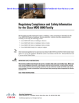
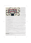
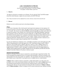
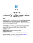
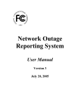
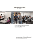
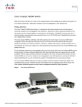
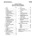
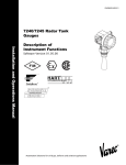
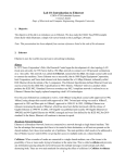
ATT-TP76440-002 Ethernet Testing using the Acterna Test Set Abstract: Presented in this document are the methods and procedures to test Ethernet Services using the Acterna Test Set. Audience: The primary audience for this document are AT&T LOCAL EXCHANGE company personnel in the following disciplines, Local Field organization (LFO-IN), Special Services (LFO-OUT), Information Technology Operations, Switch Capacity Planner/Engineer, Transport Equipment Engineer (TEE), Facility Equipment Engineer (FEE), Digital Transport Engineer (DTE), Maintenance Engineer, Space Planner, Frame Planner, Long Range Technical Planners, Outside Plant Engineering, Fundamental Network Planning, Special Services I/M and Local Field Operations (Central Office ) LFO-IN. This document is to be used internally within AT&T LOCAL EXCHANGE companies and their Authorized AT&T Approved Vendors and has a limited distribution subject to the header/footer information. Effective Date: June 29, 2005 Date Issued: Issue 1, June 29, 2005 Expires On: Reissue of this document. Related Documents: See Reference Section of this document and ATT-TP76412, ATT-TP76440 & ATT002-316-076. Canceled/Superceded Doc: N/A Issuing Dept: AT&T Services Inc., Network Planning & Engineering (Transport & Common Systems) and Outside Plant (OSP) Construction Business Unit: Network Documents Coordinator: Wing Eng, Area Manager-Network Planning & Engineering, AT&T Services Inc.(925) 823-4616, E-Mail: [email protected] Authors: Wing Eng, Area Manager-Network Planning & Engineering, AT&T Services Inc. (925) 823-4616, E-Mail: [email protected] Bruce E. Jones, Associate Director-Network Planning & Engineering, AT&T Services Inc. (817) 338-6266, E-Mail: [email protected] © 2004-2005 AT&T Knowledge Ventures All rights reserved.. Ethernet Testing using the Acterna Test Set June 29, 2005 AT&T Services Inc. ATT-TP76440-002, Issue 1 Table of Contents 1. COPYRIGHT PAGE .................................................................................................................... 3 2. REASONS FOR REISSUE ......................................................................................................... 4 3.TURN-UP TESTING PROCEDURES AND EXPECTED RESULTS........................................... 4 3A. ETHERNET LINK CONNECTIVITY TEST PROCEDURE................................................................... 4 3B. FRAME GENERATION .............................................................................................................. 5 3C. SIGNAL THROUGHPUT............................................................................................................. 5 3C.1. Constant Load Test....................................................................................................... 6 3C.2. Constant Load Test Expectations ................................................................................. 6 3C.3. Link Stats Expectations................................................................................................. 6 3C.4. Link Counts Expectations.............................................................................................. 8 3C.5. Error Stats Expectations ............................................................................................... 9 3D. END-TO-END TESTING ILLUSTRATION ...................................................................................... 9 3E. NOTE ON SENDING DELIBERATE ERRORS .............................................................................. 10 3F. TEST SET INTEROPERABILITY ................................................................................................. 11 3F.1 Same Type Test Sets ................................................................................................... 11 3F.2 Different Type Test Sets............................................................................................... 11 3F.3 Cable Test Devices ...................................................................................................... 12 4. TESTING JOB AIDS USING THE ACTERNA TEST SET ....................................................... 13 5. NON-SUPPORTED FEATURES AND EXPECTATIONS ........................................................ 30 5A. AUTO-NEGOTIATION .............................................................................................................. 30 5B. FLOW CONTROL .................................................................................................................... 30 5C. FAULT PROPAGATION ............................................................................................................ 31 5D. THROUGHPUT ....................................................................................................................... 31 5E. PERFORMANCE METRICS ....................................................................................................... 31 5F. JUMBO FRAMING ................................................................................................................... 32 5G. LAYER 2 PROTECTION AGGREGATION .................................................................................... 32 6.REFERENCES ........................................................................................................................... 33 7.CONTACTS................................................................................................................................ 34 7A. AT&T CONTACTS ................................................................................................................. 34 7B. STRATEGIC SUPPLIER CONTACTS .......................................................................................... 34 © 2004-2005 AT&T Knowledge Ventures All rights reserved.. 2 Ethernet Testing using the Acterna Test Set June 29, 2005 AT&T Services Inc. ATT-TP76440-002, Issue 1 1. Copyright Page Notice: This document is an unpublished work protected by the United States copyright laws and is proprietary to AT&T Properties, Disclosure, copying, reproduction, merger, translation, modification, enhancement, or use by anyone other than authorized employees or licensees of AT&T Properties,. without the prior written consent of AT&T Properties, . is prohibited. © 2004-2005 AT&T Knowledge Ventures All rights reserved.. All rights reserved. Trademarks: Windows 95, 97, 98, 2000, NT, ME, XP, Excel, Word for Windows, PowerPoint, Internet Explorer, Office Professional 97, Visio 2002, Visio Professional 2002, Visio Enterprise Network Tools and Microsoft are trademarks of the Microsoft Corporation. Netscape Navigator is a trademark of the Netscape Corporation. AutoCAD 2000, 2000i & 2002 are trademarks of the Autodesk Corporation. Adobe Acrobat 7.0 and PDF are trademarks of the Adobe Corporation. Common Language®, SWITCH®, TIRKS®, CLEI®, CLLI® and CLFI® are registered trademarks of Telcordia Technologies Inc. ANSI is a trademark of the American National Standards Institute. TIA is a service mark of the Telecommunications Industry Association. EIA is a service mark of the Electronic Industries Alliance. IEEE is a trademark of the Institute of Electrical and Electronic Engineers. All other trademarks belong to their respective owners. Publisher: Network Planning & Engineering – Common Systems & Transport Standards AT&T Services Inc. 1116 Houston Street RM 840 Ft. Worth, Texas 76102 © 2004-2005 AT&T Knowledge Ventures All rights reserved.. 3 Ethernet Testing using the Acterna Test Set June 29, 2005 AT&T Services Inc. ATT-TP76440-002, Issue 1 2. Reasons for Reissue Updates to this document will be highlighted in this section. 3.Turn-Up Testing Procedures and Expected Results This Section contains procedures for initial verification of equipment related for the installation of AT&T LOCAL EXCHANGE companies Ethernet services. Use of these procedures will help ensure a successful service hand-off and reduce repeat troubles. This document also covers testing procedures that are features of a variety of test sets. Test and Turn-up procedures covered in this document are those utilizing two Acterna (Test Set) FST-2802 Test Pads. The test device must have the capability of operating as an Ethernet switch port on a circuit. Ethernet switches are capable of interpreting Ethernet frames (data); therefore, you can use the test set to ensure physical and data layer integrity by transmitting and analyzing Ethernet frames. The Acterna FST-2802 Test Pad is already being used by AT&T LOCAL EXCHANGE companies personnel in connection with the Installation and Maintenance of Central Office Ethernet switches and the deployment of AT&T’s current Gig-E offering GigaMAN. The following test will determine the physical characteristics of the Ethernet element. Testing the Ethernet Element from end to end will give a true test of all segments of the circuit. The same procedure can be of use; testing the different segments when needing to isolate a defect for repair purposes. The three tests performed are essential for the successful deployment of Ethernet services. These tests are to determine: • • • Connectivity Throughput QoS Ethernet Elements The Ethernet elements that the 10/100BaseT signals passed through to complete the end-totesting are the following: • • • • • ADC FMT (Fiber Management Tray) ADC RJ-45 to RJ-45 (EIA/TIA T568-B specification) ADC Media Converter Module 10/100BaseT-100Base-LX, RJ-45, 1310nm,FP Laser, SC 10ft Cat 5e/5t patch cords 10ft Fiber Optic SC-UPC patch cords 3A. Ethernet Link Connectivity Test Procedure 1. Connectivity – Signal (Light) 2. Synchronization (Bit Stream from far end) 3. Link Establishment with far end test set (Both ends communicating) © 2004-2005 AT&T Knowledge Ventures All rights reserved.. 4 Ethernet Testing using the Acterna Test Set June 29, 2005 AT&T Services Inc. ATT-TP76440-002, Issue 1 Before you transmit and receive traffic (Ethernet frames) over a circuit, you must initialize an Ethernet link. At a minimum, initializing a link involves connecting compatible test sets that emulates Ethernet switch ports to a circuit, and allows the test sets to transmit idle traffic. Connectivity Link Establishment To specify link initialization parameters 1 Using the application buttons, select a TERM 10/100 (Unit A) 2 Select SETUP. A group of quick configuration buttons appears. 3 Select Link Init. The Link Init tab appears. 4 Set the parameters to Auto Neg On, Flow Control On. 5 Click OK to get back to the main user interface 6 Repeat the same process at the far end test (Unit B). 7 Connect each test set each end of circuit (See Figure 1 and 2) 8 Turn Signal ON for Unit A 9 Now look for Signal (from previous step), Sync LEDs on the test set of Unit B. If link is not established check the settings on both devices and try again. 10 Turn Signal ON for Unit B 11 Now look for Signal (from previous step), Sync LEDs on the test set of Unit A. If link is not established check the settings on both devices and try again. 12 You now have an Ethernet connection between the two ends of the circuit. This will be indicated by a Sync LED on both test sets at either end of the circuit. 3B. Frame Generation 1. Monitor the LED’s for Signal, Sync, Link Active, and Frame Detect. 2. All are lit indicating the Test Pad detects a signal, obtains synchronization, link is active, and frames are detected. 3. On the left results pane, select the Result Category button. 4. Select Link Stats and record stats: Average Bandwidth Received- 100% Current Bandwidth- 100% Shows a continual growing number of frames received and frames transmitted. 5. On the right results pane, select the Result Category Button. 6. Select the Error Stats and record stats: Symbol Errors-0 FCS Errored Frames- 0 Runts-0 Undersized Frames-0 Oversized Frames-0 Errored Frames- 0 3C. Signal Throughput The test set supports three traffic load types. They are Constant Rate, Burst, or Ramp. For this application we will use a Constant Load type at 10/100. The First step is to prepare the test Ethernet frames for transmission. © 2004-2005 AT&T Knowledge Ventures All rights reserved.. 5 Ethernet Testing using the Acterna Test Set June 29, 2005 AT&T Services Inc. ATT-TP76440-002, Issue 1 3C.1. Constant Load Test To choose a frame profile 1. 2. 3. 4. 5. 6. Select Setup. A menu appears listing the Quick Configuration buttons. Select Tx Profiles. The Tx Profiles tab appears. Under Selections/Tx Profile, select the Profile P1. There is no need to change anything in the Settings fields. Repeat for the far end test set (Unit B) . To set-up for a Constant Load Test 1 2 3 4 5 6 7 8 9 Select Setup (if not already in set-up). Select the Traffic Tab. Select Const. Select %BW and 100%. Select OK and return to the main user interface. Repeat steps 1 through 5 for the far end test set (Unit B). Select restart to clear any errors, and press button to Start Traffic. You are now transmitting traffic at 100 percent of the circuit capability. Note if errors occur. See the Test Results section for details on results categories and values. Perform the 100% transmission test for 8 minutes or more. Repeat process for far end unit. 3C.2. Constant Load Test Expectations On the left results pane, select the Result Category button. Select Link Stats and record stats: Average Bandwidth Received- 100% Current Bandwidth- 100% Shows a continual growing number of frames received and frames transmitted. On the right results pane, select the Result Category Button. Select the Error Stats and record stats: Symbol Errors-0 FCS Errored Frames- 0 Runts-0 Undersized Frames-0 Oversized Frames-0 Errored Frames- 0 3C.3. Link Stats Expectations The Link Stats category lists link statistics such as the average frame rate, peak frame rate, and the number of frames transmitted, etc. To view Link Stats results, set the result category to Link Stats. The following is a list and a general explanation of all the Link Stats results. Bold type indicates elaboration as to the relevance to this specific test procedure. © 2004-2005 AT&T Knowledge Ventures All rights reserved.. 6 Ethernet Testing using the Acterna Test Set June 29, 2005 AT&T Services Inc. ATT-TP76440-002, Issue 1 Link Statistics (Stats) Test Expectations Benchmark Test Result Expectations Total Util %, Average Total Util %, Cur Total Util %, Peak Frame Rate, Average Frame Rate, Cur Frame Rate, Min Frame Rate, Peak Frame Size, Min Frame Size, Max Received Frames Transmitted Frames Rx Bits/Sec, Cur Tx Bits/Sec, Cur Delay, Max Description The average bandwidth received, expressed as a percentage of the entire 1 Gbps of available bandwidth. The average is calculated over the time period elapsed since the last test restart. The current bandwidth received expressed as a percentage of the entire 1 Gbps of available bandwidth. This result indicates what rate of traffic is making it across the link from the far end. The peak bandwidth utilized by the received traffic expressed as a percentage of the entire 1 Gbps of available bandwidth since the last test restart. The average rate of received frames, expressed in frames per second. The average is calculated over the time period elapsed since the last test restart. The current rate of received frames, expressed in frames per second. This measurement is an average taken over the prior second of test time. The minimum rate of received frames over a one second period, expressed in frames per second. The maximum rate of received frames over a one second period, expressed in frames per second. The size in bytes of the smallest frame seen since last test restart. The size in bytes of the largest frame seen since last test restart. The number of frames received since the last test restart. The number of frames transmitted since the last test restart. In a loop back test Received and Transmitted frames should be equal. If they are not, an error may have occurred. Check error counters. The current bandwidth utilized by the received traffic expressed in bits per second. This measurement is an average taken over the prior second of test time. In a loopback test, the Rx and TX Bits/Sec Cur values should track together. This is also true for an end to end test, if the same profile settings are used. The current bandwidth utilized by the transmitted traffic expressed in bits per second. This measurement is an average taken over the prior second of test time. This will tell us how fast we are transmitting. In the Ramp Test, once a pause frame is received, we want to check this result to see that it settles in near the rate in the customer contract. The maximum Round Trip Delay measurement since the last test restart. You must transmit an Acterna payload to measure round trip delay. RTD measurements are only performed when using a Constant traffic type. Check the service contract or SLA for a max RTD parameter. If there is none, a benchmark for the particular network is still recommended. In general, the Max RTD should not be vastly greater than the average. A significant differential © 2004-2005 AT&T Knowledge Ventures All rights reserved.. 7 Ethernet Testing using the Acterna Test Set June 29, 2005 Delay, Min Delay, Avg. Svc Disruption AT&T Services Inc. ATT-TP76440-002, Issue 1 would indicate packet jitter is being imposed on the circuit by a switching or buffering device. The minimum round trip delay calculated in microseconds. You must transmit an Acterna payload to measure round trip delay. RTD measurements are only performed when using a Constant traffic type. Check the service contract or SLA for an average. RTD parameter. If there is none, a benchmark for the particular network is still recommended. In general, this value should be under 100 ms. Average delays in excess of 100 ms might impair the performance of delay sensitive applications. The average round trip delay calculated in microseconds. You must transmit an Acterna payload to measure round trip delay. RTD measurements are only performed when using a Constant traffic type The service disruption time (maximum inter-frame gap) when service switches to a protect line calculated in milli-seconds. 3C.4. Link Counts Expectations Test Result Received Frames Transmitted Frames RX Acterna Frames PAUSE Frames Out of Seq Frames VLAN Frames Unicast Frames Multicast Frames Broadcast Frames 64 Byte Frames 65-127 Byte Frames 128-255 Byte Frames 256-511 Byte Frames 512-1023 Byte Frames 1024-1518 Byte Frames Description A count of frames received since the last test restart, including errored frames. A count of frames transmitted since the last test restart. A count of received frames with Acterna test packets. A count of PAUSE frames received from a remote Ethernet device. This should be 0 until using the Ramp Test. When the bandwidth approaches the provisioned limit, this counter should increment by at least 1. A count of out of sequence frames. Only valid while receiving frames with the Acterna payload. If this result is non zero, it indicates that frames are being lost on the circuit under test. A count of VLAN frames as defined in IEEE 802.p/q. This result only appears for Test Pads with the VLAN Tagging option. The number of unicast frames received since the last test restart. The number of multicast frames received since the last test restart. The number of broadcast frames received since the last test restart. A count of frames with a length of 64 bytes. A count of frames with lengths between 65 and 127 bytes, inclusive. A count of frames with lengths between 128 and 255 bytes, inclusive. A count of frames with lengths between 256 and 511 bytes, inclusive. Since we chose a frame size of 256, all the frames should be counted here. If you chose a different frame size, the counts will fall into the appropriate bins. A count of frames with lengths between 512 and 1023 bytes, inclusive. A count of frames with lengths between 1024 and 1518 bytes, © 2004-2005 AT&T Knowledge Ventures All rights reserved.. 8 Ethernet Testing using the Acterna Test Set June 29, 2005 AT&T Services Inc. ATT-TP76440-002, Issue 1 inclusive. 3C.5. Error Stats Expectations The Error Stats category lists error statistics such as the number of symbol errors, FCS errored frames, and runts. In this test procedure, any non-zero value for these Error Stats, constitutes a test failure. Test Result Description Symbol Errors A count of invalid 10-bit code words received on the physical layer. This result will not increment more than one time per frame. A count of frames containing Frame Check Sequence (CRC) errors. FCS Errored Frames Runts Undersized Frames Oversized Frames Errored Frames A count of frames under the required 64 byte frame length containing Frame Check Sequence (CRC) errors. A count of frames under the minimum 64 byte frame length. A count of frames over the maximum 1518 byte frame length. A summed count of FCS Errored Frames, Runts, Undersized Frames, and Oversized Frames. 3D. End-to-End Testing Illustration © 2004-2005 AT&T Knowledge Ventures All rights reserved.. 9 Ethernet Testing using the Acterna Test Set June 29, 2005 AT&T Services Inc. ATT-TP76440-002, Issue 1 3E. Note on Sending Deliberate Errors In the transport test world it is common to send a bit error across a circuit once BERT pattern synchronization has been achieved. This assures the technician(s) that the proper end locations are the ones that are synchronized. The parallel for Ethernet testing is to send a FCS error. However, one of the inherent traits of Ethernet is that error frames are discarded by Ethernet aware interfaces. In the case of the 10/100 and Gigabit services over SONET, the Network Element interfaces are Ethernet aware. Frames with deliberate FCS errors sent by the test set © 2004-2005 AT&T Knowledge Ventures All rights reserved.. 10 Ethernet Testing using the Acterna Test Set June 29, 2005 AT&T Services Inc. ATT-TP76440-002, Issue 1 will be dropped by the locally connected Ethernet port. Instead of seeing an FCS, what the far end test set will see is that a frame was lost. In contrast, the DWDM application would behave differently. The ports on the DWDM device handle traffic with complete transparency. Error frames are passed through along with valid frames. The far end test set would count an FCS error. However, since the test set is behaving as an Ethernet element, if it were in loop back, it would discard an error frame just as a switch would. In this way, the technique so often used in the TDM world can still be used for most Ethernet Transport applications. Caution. Testing of cables, jumpers and frame facilities need to be performed from end-to-end without the attachment of active Ethernet devices. Perform testing from test set to test set to validate Category 5t facilities. 3F. Test Set Interoperability 3F.1 Same Type Test Sets With the deployment of Ethernet type services, it has been well known that there are idiosyncrasies and standards differences between products and manufacturers. As a result, it is most advantageous that when end-to-end testing is performed, that the same type of test set and model from the same manufacturer is used for this testing. The two test set manufacturers standardized within AT&T (Sunrise and Acterna) work extremely effectively when the same test set is used on each end of the circuit. The general availability of the Sunrise Telecom MTT-28/SSMTT-29 and Acterna 2802 Test Sets will be December 2003. 3F.2 Different Type Test Sets Ethernet testing using different manufacturers products dictates special handing due to the soft standards found within the Ethernet architecture. While AT&T has selected two outstanding test sets from two different manufacturers (Sunrise Telecom & Acterna), both which will test to each other in an end-to-end test. The following information was ascertained through multiple interoperable tests. When the following stipulations are met, both test sets will function with one another. If any other manufacturer test sets are used, it will be necessary for interoperable lab tests be performed to insure their interoperability compliance as well. 3F.2.A End-to-End testing The Acterna 2802 must be configured to run an All 1s or All 0s test pattern and the MAC address of the Sunrise Telecom module needs to be entered as the Destination MAC address for the 2802. Auto negotiation should be set for Disabled. © 2004-2005 AT&T Knowledge Ventures All rights reserved.. 11 Ethernet Testing using the Acterna Test Set June 29, 2005 AT&T Services Inc. ATT-TP76440-002, Issue 1 The Sunrise Telecom MTT-28 (10/100Base-T) module or the SSMTT-29 (Gigabit Ethernet) module must be configured for Layer 2, with an All 1s or All 0s test pattern, and the MAC address of the 2802 needs to be entered as the Destination MAC Address of the Sunrise Telecom module. Auto negotiation should be set for Disabled. 3F.2.B Loopback testing If the Sunrise Telecom Ethernet module is set in a manual loop back mode, the Acterna 2802 module can run clean to itself. The Sunrise Telecom Ethernet modules cannot run clean through a manual loop on the Acterna 2802. The Acterna 2802 must not be able to retransmit the Sunrise payload. 3F.3 Cable Test Devices The Westek Cable Test Device has been approved by the AT&T LOCAL EXCHANGE companies for use in the end-to-end testing of electrical 8-wire cable used for Ethernet and other electrical circuits. This device can be used to test for electrical faults (open, short, grounds) from one RJ45 end point to the other RJ45 end point. The master device attaches to one end with the remote attaching to the other. This device will tell the technician at either end the correct test and wiring configuration end-to-end. This device is suitable for all Ethernet pre-wiring before circuit placements are made. (Circuit testing will be made with the Acterna and Sunrise Telecom test sets.) The Westek device also provides talk battery in order for a hand set to be placed at each Cable Test Device which permits the remote technicians to converse with one another. The general availability of this product will be December 2003. © 2004-2005 AT&T Knowledge Ventures All rights reserved.. 12 Ethernet Testing using the Acterna Test Set June 29, 2005 AT&T Services Inc. ATT-TP76440-002, Issue 1 4. Testing Job Aids using the Acterna Test Set Tools Needed: • Service description for the circuit under test (e.g. the bandwidth to be verified) • Acterna FST-2802 TestPad with correct GBICs, quantity 2 • Appropriate fiber optic cables (duplex SC multi-mode or single-mode) Figure 1. Customer sites with EOS Handoffs The Ethernet traffic is mapped into SONET sub-rates for efficient transport across the SONET or DWDM core. This is the enabler of the “Fractional” services alluded to above. Table 1 below describes the maximum guaranteed Ethernet throughput related to the appropriate SONET mapping. This mapping flexibility allows for: • “Right-sizing” the backbone circuit for the customer needs • Conservation of core bandwidth. (Avoid reserving full STS24c channels for lesser loads) • Hitless remote upgrades as customer purchases greater bandwidth to meet growing needs. (no truck roll, no line card swaps as with OC3 to OC12 jump) Table 1. Relationship between SONET mapping and maximum throughput Transport Circuit Size STS1 STS3c STS6c STS9c STS12c STS24c STS48c % GE Interface Speed 5 15 30 45 60 100 100 Bandwidth in Mbps 50 150 300 450 600 1000 1000 © 2004-2005 AT&T Knowledge Ventures All rights reserved.. 13 Ethernet Testing using the Acterna Test Set June 29, 2005 AT&T Services Inc. ATT-TP76440-002, Issue 1 NOTE: These values are based on average EOS throughput test results with various frame sizes. Results can vary based on test equipment, frame size and line conditions. In general the SONET circuit can transport more than the Bandwidth listed in the table, but published values are rounded rather than listed in traditional Sonet/TDM sizes. For example, actual throughput on an OC12c might approach 620 Mbps with certain frame sizes, but the circuit is operating correctly as long as it operates error free to 600 Mbps. The bandwidth sold will be defined in the customer’s contract and should be part of the work document for the circuit turn up. The testing should verify error free operation of the circuit up to that bandwidth. In order to check overall provisioning of the circuit, traffic should be analyzed above the contracted rate to make sure that no traffic over the contract will pass. This test protects the provider from wasted core bandwidth due to incorrect provisioning. GBIC Descriptions Table 2 lists the GBIC types with the associated cables and connectors. Table 2. GBICs and cables Wavelength/Mode 850 nm MM 1310 nm SM GBIC Jacks Black or beige Blue Fiber Cable Orange Yellow Connector SC SC It is a requirement to use matched GBICs and the appropriate fiber optic cable when connecting the network element to the customer device or to your FST 2802 TestPad. Many Ethernet devices include support for Auto-Negotiation. This allows the element ports to automatically negotiate Ethernet parameters with the near end device such as the customer’s switch or router or, in this case, the FST-2802 TestPad. Settings required include half duplex or full duplex operation. Full duplex means that each port can both transmit and receive simultaneously. Half duplex mode means that, if required by the attached customer device. Some older Gigabit switches may require this mode. A second selectable parameter that must be addressed is Flow Control. Flow control refers to the ability to send and/or respond to pause frames. When enabled an Ethernet device will generate pause frames toward an attached device when there is too much ingress traffic. This capability allows Ethernet devices to smooth out the bursty nature of Ethernet traffic. This is what allows a 1000 Mbps capable Ethernet port to connect to a smaller SONET sub-rate, such as an STS3c (~150 Mbps). For any fractional rate service, it is imperative that Flow Control be enabled on the customer equipment. Ethernet Testing Concepts There are three main test criteria for verifying proper operation of the equipment and associated provisioning for the Gigabit Ethernet Service. There is also a fourth test related to the SONET backbone. Link Connectivity: This involves verifying that the ports on either end of the circuit operate properly by establishing a local Ethernet link with the attached test equipment. The FST-2802 is © 2004-2005 AT&T Knowledge Ventures All rights reserved.. 14 Ethernet Testing using the Acterna Test Set June 29, 2005 AT&T Services Inc. ATT-TP76440-002, Issue 1 being used to emulate the customer’s end device. Additionally, connectivity also refers to the two desired end points (test set to test set) across the SONET network having communication. Throughput: This involves verifying that the contracted throughput (Mbps) is delivered, error free, by the circuit under test. In the case of sub-rate Gigabit services, this also involves verifying proper configuration and operation of the flow control features. Pause: This is a measurement to ensure that a device that is responds when incoming traffic is coming at too high of a rate. The Pause frame is transmitted to the device which is overwhelming the receiver and initiates a pause in transmiting adequate to clear the buffer. This is a function of line rate and processor speed. Burst: In order to emulate realistic customer traffic patterns, the customer the test set can be programmed to transmit in burst mode. This provides a more realistic network simulation for circuit provisioning. About the FST-2802 The FST-2802 is the ideal telecommunications solution for testing and verifying Ethernet network elements and services. It is an additional module for the widely deployed TTC/Acterna TestPad platform, which includes the 2209, 2310, 2510 and more. It is designed for field use by transport technicians involved with installation, commissioning, service turn-up, and troubleshooting of TDM, SONET, and now Ethernet Transport Services. Figure 3. FST-2802 TestPad This application note is not intended to provide an exhaustive training on every aspect of the FST-2802 features or menu structure. Instead, the following instructions will hone in on specific applications surrounding services built on the 15454 and the G1000-4 line card. A complete overview of the TestPad and the FST-2802 Module can be gained from the user manual as well as from context sensitive help screens embedded in the unit. Test Procedures © 2004-2005 AT&T Knowledge Ventures All rights reserved.. 15 Ethernet Testing using the Acterna Test Set June 29, 2005 AT&T Services Inc. ATT-TP76440-002, Issue 1 This section provides step-by-step instructions for performing Gigabit Ethernet tests using the TestPad. End to End or Single Ended Testing Since Auto-Negotiation of Ethernet link parameters and Flow Control performance are local events at each end of the circuit, end to end testing with 2 FST-2802’s provides the most thorough verification of all aspects of the circuit operation. Figure 4 depicts this scenario. Figure 4. Set-up for 2 Ended Gigabit Circuit Test SONET or DWDM Auto- Pause Frames Auto-Negotiation Pause Frames Connectivity: Ethernet link initialization The recommended setting for customer equipment and therefore for the FST-2802 as it emulates customer equipment is for auto-negotiation and flow control to both be turned on. To specify link initialization parameters 1 Using the application buttons, select a TERM>1G Ethernet for fiber or 10/100 Ethernet for copper. © 2004-2005 AT&T Knowledge Ventures All rights reserved.. 16 Ethernet Testing using the Acterna Test Set June 29, 2005 AT&T Services Inc. ATT-TP76440-002, Issue 1 2 Tap SETUP. A group of quick configuration buttons appears. 3 Tap Link Init. The Link Init tab appears. 4 Tap the AutoNeg – On Button 5 Tap the AutoNeg button that becomes available. A window appears listing the autonegotiation capabilities. For Pause Capable select the following: Rx Only: This will allow the FST 2802 to properly pause traffic when it receives Pause Frames. For Full Duplex (FDX) and Half Duplex (HDX) select: Yes on both (will support both) 6 Click OK on both screens to get back to the main user interface 7 Connect the FST-2802 to the network element using the proper cable (Fiber or Copper as appropriate). For Fiber tap the gray flashing Laser OFF button on the lower left of the screen to activate the FST-2802 laser. The button will illuminate yellow and say “Laser ON”. The 2 Gigabit ports should now perform auto-negotiation and establish the Ethernet link. 8 Since this is a 2-ended test, perform the same process at the far end FST-2802. 9 Look for Signal, Sync, and Link Active LEDs on the right side of the FST-2802. If you do not get a Link, make sure that the technician at the far end has the 2802 set up through step 7 of this procedure. 10 You now have an Ethernet connection between the locally connected G1000-4 port and the test device. © 2004-2005 AT&T Knowledge Ventures All rights reserved.. 17 Ethernet Testing using the Acterna Test Set June 29, 2005 AT&T Services Inc. ATT-TP76440-002, Issue 1 Throughput Testing The FST-2802 supports three traffic load types. They are Constant Rate, Burst, or Ramp. For this application we will use both Constant Rate and Ramp. The reasons we’ll use these two will be explained as we go along. Before we do that, we need to set-up some Ethernet frames to actually send. To define a frame profile 1 Tap Setup. A menu appears listing the Quick Configuration buttons. 2 Tap Tx Profiles. The Tx Profiles tab appears. 3 4 Under Selections/Tx Profile, select the Profile P1. In the Settings fields, specify the frame characteristics for the traffic transmitted using the profile. 5 Under Profile, select Profile 1 to set-up the profile we chose to transmit 6 Under Length select 256 You can ignore DA Type, Dest Address, Frame, and EtherType and VLAN Tag settings for this application as they are not relevant. 7 Under Payload select Acterna 8 Now Tap on the Traffic tab © 2004-2005 AT&T Knowledge Ventures All rights reserved.. 18 Ethernet Testing using the Acterna Test Set June 29, 2005 9 10 11 12 13 14 AT&T Services Inc. ATT-TP76440-002, Issue 1 Select Constant and enter the bandwidth the customer is buying in either Mbps or by % of a 1G or 10/100 M load as appropriate. See the customer contract or work document. Tap OK For a 2 ended test, perform steps 2 through 11 at the far end. From the main user interface screen, make sure the laser is on (lower left > flashing yellow) and Signal, Sync, and Link Active are all still lit. If there are any errors (red LEDs), tap Restart in the upper right. Now tap Start Traffic. You are now transmitting across the link. Desired Results. The Summary Category should indicate All Summary Results OK. The Link Counts category should show Out of Seq Frames equal to 0. Link Utilization should show full bandwidth as being transmitted by the far end. See the combined results section at the end of the application note for detailed explanations. Testing Pause Functionality For a full Gigabit service (1000Mbps) the Constant rate traffic test we just performed above would be sufficient. However, we mentioned that we would use a Ramp traffic type to test the Pause functionality of the network elements. What ramp allows us to do is to gradually increase the traffic rate until we approach and exceed the provisioned backbone bandwidth. The result seen should be a pause frame issued by the network element port back towards the FST-2802. Also, we should not be able to transmit over the contract rate without incurring Out of Sequence frames. Since the Flow Control/Pause frame functionality is independent at both ends, this test should be performed at each end of the circuit with the far end looped back. Perform on one side at a time. © 2004-2005 AT&T Knowledge Ventures All rights reserved.. 19 Ethernet Testing using the Acterna Test Set June 29, 2005 AT&T Services Inc. ATT-TP76440-002, Issue 1 To set-up for a Pause (Ramp) Test In order to perform Ramp test, we will need to establish a loop at one end of the Ethernet network. This can be done in one of two ways: • • Local Loop with the FST-2802. Personnel operating the FST-2802 at the far end can tap the LLB button on the user interface. This will cause the FST-2802 to return all of the error free traffic that it receives. The near end FST-2802 should receive all the traffic that it sends. Any missing or errored traffic will be noted. The time delta for the round trip is calculated. Note the LLB button on the user interface in Figure 5. Remote Loop with the FST-2802. Personnel at the near end FST-2802 can issue a Loop-Up command to the far end FST-2802. When the loop up command is confirmed and traffic is started, the near end FST-2802 should receive all the traffic that it sends. Any missing or errored traffic will be noted. The time delta for the round trip is calculated. Upon completion, the near end FST-2802 operator can tap the loop down button. Note the Loop Up/Down buttons on the user interface in Figure 5. 1 2 Tap Setup. Tap the Traffic Tab 3 4 Select Ramp Select 5.0 seconds Time Step and 5 % for Load Step. (All the 15454 sub-rates are divisible by 5) Select all three of the Stop Load Increment criteria and set them at 1. Tap OK and return to the main user interface You can now turn on the Laser, Tap restart to clear any errors, and tap Start Ramp You are now transmitting traffic at increasing increments to determine at what bandwidth the circuit experiences Errored Frames, Dropped Frames, or Pause Frame. Note at what rate any one of these events occurs. The desired result is that there are no error or 20 © 2004-2005 AT&T Knowledge Ventures All rights reserved.. 5 6 7 8 Ethernet Testing using the Acterna Test Set June 29, 2005 AT&T Services Inc. ATT-TP76440-002, Issue 1 dropped frames and that pause frames are seen at the approximate BW that the customer is being sold. NOTE: If errors begin to occur, but no Pause Frame has been received, verify that Flow Control Negotiation “enabled” on the network element. Desired Results. A pause frame should be counted in the Link Counts category. When it is, the Ramp function will stop incrementing. The Link Stats category should show a Current Utilization equal to that which the customer is being provisioned. (e.g. for a STS12c customer (600Mbps) a pause frame should have been issued when the test set made the jump from 600Mbps to 650Mbps. Upon seeing the Pause frame, the 2802 will down speed to 600Mbps or 60% utilization) 9 10 See the combined results section at the end of the application note for detailed explanations. To set-up for a Burst Test 1. 2. Tap Setup. Tap the Traffic Tab 2 3 4 5 6 7 8 9 10 Tap % BW Tap Load 100% Tap Frame Sized Fixed Tap Frames/Burst 16 Tap No of Bursts “Continuous” Tap OK to return to the main screen. Complete steps 1-7 on the far end test device. Start Traffic on both 2802’s In “Summary” results ensure all results OK. © 2004-2005 AT&T Knowledge Ventures All rights reserved.. 21 Ethernet Testing using the Acterna Test Set June 29, 2005 AT&T Services Inc. ATT-TP76440-002, Issue 1 Test Results Section Figure 5 above provides us with our desired results. The left hand results screen is in the Summary category and indicates that there are no error conditions to report. Figure 6 below depicts how the FST-2802 makes the existence of errors very obvious. The following screens and accompanying discussion provide more depth to the analysis. Here again, we do not seek to provide an explanation for every result category that the FST-2802 provides, but instead hone in on what is most relevant to this application. Figure 6. User Interface with Summary and LED results displayed The most relevant results from this test procedure reside in 3 categories: Link Stats, Link Counts and Error Stats © 2004-2005 AT&T Knowledge Ventures All rights reserved.. 22 Ethernet Testing using the Acterna Test Set June 29, 2005 AT&T Services Inc. ATT-TP76440-002, Issue 1 Figure 7. User Interface with Link Stats and Link Counts results displayed Figure 8. User Interface with All Results OK © 2004-2005 AT&T Knowledge Ventures All rights reserved.. 23 Ethernet Testing using the Acterna Test Set June 29, 2005 AT&T Services Inc. ATT-TP76440-002, Issue 1 © 2004-2005 AT&T Knowledge Ventures All rights reserved.. 24 Ethernet Testing using the Acterna Test Set June 29, 2005 AT&T Services Inc. ATT-TP76440-002, Issue 1 Link Stats results The Link Stats category lists link statistics such as the average frame rate, peak frame rate, and the number of frames transmitted, etc. To view Link Stats results, set the result category to Link Stats. The following is a list and a general explanation of all the Link Stats results. Bold type indicates elaboration as to the relevance to this specific test procedure. Table 3. Link Stats Results Test Result Total Util %, Avg Description The average bandwidth received, expressed as a percentage of the entire 1 Gbps of available bandwidth. The average is calculated over the time period elapsed since the last test restart. Total Util %, Cur The current bandwidth received expressed as a percentage of the entire 1 Gbps of available bandwidth. This result indicates what rate of traffic is making it across the link from the far end. In a Constant Rate test this should be equal to the customer contract rate. For a Ramp Test this should ramp until it is at the contract rate and stop when a Pause Frame is seen. Total Util %, Peak The peak bandwidth utilized by the received traffic expressed as a percentage of the entire 1 Gbps of available bandwidth since the last test restart. Frame Rate, Avg The average rate of received frames, expressed in frames per second. The average is calculated over the time period elapsed since the last test restart. Frame Rate, Cur The current rate of received frames, expressed in frames per second. This measurement is an average taken over the prior second of test time. Frame Rate, Min The minimum rate of received frames over a one second period, expressed in frames per second. Frame Rate, Peak The maximum rate of received frames over a one second period, expressed in frames per second. Frame Size, Min The size in bytes of the smallest frame seen since last test restart. Frame Size, Max The size in bytes of the largest frame seen since last test restart. Received Frames The number of frames received since the last test restart. Transmitted Frames The number of frames transmitted since the last test restart. In a loop back test Received and Transmitted frames should be equal. If they are not, an error may have occurred. Check error counters. Rx Bits/Sec, Cur The current bandwidth utilized by the received traffic expressed in bits per second. This measurement is an average taken over the prior second of test time. In a loopback test, the Rx and TX Bits/Sec Cur values should track together. This is also true for an end to end test, if the same profile settings are used. Tx Bits/Sec, Cur The current bandwidth utilized by the transmitted traffic expressed in bits per second. This measurement is an average taken over the prior second of test time. This will tell us how fast we are transmitting. In the Ramp Test, once a pause frame is received, we want to check this result to see that it settles in near the rate in the 25 © 2004-2005 AT&T Knowledge Ventures All rights reserved.. Ethernet Testing using the Acterna Test Set June 29, 2005 AT&T Services Inc. ATT-TP76440-002, Issue 1 customer contract. The maximum Round Trip Delay measurement since the last test restart. You must transmit an Acterna payload to measure round trip delay. RTD measurements are only performed when using a Constant traffic type. Check the service contract or SLA for a max RTD parameter. If there is none, a benchmark for the particular network is still recommended. In general, the Max RTD should not be vastly greater than the average. A significant differential would indicate packet jitter is being imposed on the circuit by a switching or buffering device. The minimum round trip delay calculated in microseconds. You must transmit an Acterna payload to measure round trip delay. RTD measurements are only performed when using a Constant traffic type. Check the service contract or SLA for an avg. RTD parameter. If there is none, a benchmark for the particular network is still recommended. In general, this value should be under 100 ms. Average delays in excess of 100 ms may impair the performance of delay sensitive applications. Delay, Max Delay, Min Delay, Avg. Svc Disruption The average round trip delay calculated in microseconds. You must transmit an Acterna payload to measure round trip delay. RTD measurements are only performed when using a Constant traffic type The service disruption time (maximum inter-frame gap) when service switches to a protect line calculated in milli-seconds. Table 4. Link Counts results Test Result Received Frames Transmitted Frames RX Acterna Frames PAUSE Frames Out of Seq Frames VLAN Frames Unicast Frames Description A count of frames received since the last test restart, including errored frames. A count of frames transmitted since the last test restart. A count of received frames with Acterna test packets. A count of PAUSE frames received from a remote Ethernet device. This should be 0 until using the Ramp Test. When the bandwidth approaches the provisioned limit, this counter should increment by at least 1. A count of out of sequence frames. Only valid while receiving frames with the Acterna payload. If this result is non zero, it indicates that frames are being lost on the circuit under test. A count of VLAN frames as defined in IEEE 802.p/q. This result only appears for TestPads with the VLAN Tagging option. The number of unicast frames received since the last test restart. © 2004-2005 AT&T Knowledge Ventures All rights reserved.. 26 Ethernet Testing using the Acterna Test Set June 29, 2005 Multicast Frames Broadcast Frames 64 Byte Frames 65-127 Byte Frames 128-255 Byte Frames 256-511 Byte Frames 512-1023 Byte Frames 1024-1518 Byte Frames AT&T Services Inc. ATT-TP76440-002, Issue 1 The number of multicast frames received since the last test restart. The number of broadcast frames received since the last test restart. A count of frames with a length of 64 bytes. A count of frames with lengths between 65 and 127 bytes, inclusive. A count of frames with lengths between 128 and 255 bytes, inclusive. A count of frames with lengths between 256 and 511 bytes, inclusive. Since we chose a frame size of 256, all the frames should be counted here. If you chose a different frame size, the counts will fall into the appropriate bins. A count of frames with lengths between 512 and 1023 bytes, inclusive. A count of frames with lengths between 1024 and 1518 bytes, inclusive. Error Stats Results The Error Stats category lists error statistics such as the number of symbol errors, FCS errored frames, and runts. In this test procedure, any non-zero value for these Error Stats, constitutes a test failure. Table 5. Error Stats results Test Result Symbol Errors FCS Errored Frames Runts Undersized Frames Oversized Frames Errored Frames Description A count of invalid 10-bit code words received on the physical layer. This result will not increment more than one time per frame. A count of frames containing Frame Check Sequence (CRC) errors. A count of frames under the required 64 byte frame length containing Frame Check Sequence (CRC) errors. A count of frames under the minimum 64 byte frame length. A count of frames over the maximum 1518 byte frame length. A summed count of FCS Errored Frames, Runts, Undersized Frames, and Oversized Frames. Note on Sending Deliberate Errors In the transport test world it is common to send a bit error across a circuit once BERT pattern synchronization has been achieved. This assures the technician(s) that the proper end locations are the one’s that are synchronized. The parallel for Ethernet testing is to send an FCS error. However, one of the inherent traits of Ethernet is that errored frames are discarded by Ethernet interfaces. In this application all frames with deliberate FCS errors sent by the FST-2802 will be dropped by the locally connected G1000-4 port. Instead of seeing an FCS, what the far end FST-2802 will see is that a frame was lost. Similarly, if the far end had a hard loopback and an FCS error was injected, an Out of Sequence/Lost Frame would be the result. In this way, the technique so often used in the TDM world can still be used for most Ethernet Transport applications. 27 © 2004-2005 AT&T Knowledge Ventures All rights reserved.. Ethernet Testing using the Acterna Test Set June 29, 2005 AT&T Services Inc. ATT-TP76440-002, Issue 1 Appendix B: Brief Ethernet Basics This Appendix provides a very brief outline of the technology through some of it’s terms. Please contact Acterna for a more detailed explanation of Ethernet technology. Ethernet Standards - IEEE 802.3 Ethernet is a data transmission protocol, as opposed to SONET which is optimized for telephony applications. SONET continuously transmits data between devices in order to preserve synchronization. “Dummy” bits fill gaps between user data. SONET is a connection-oriented protocol. Ethernet only sends information when needed. This is a connectionless protocol. 10 Mb Ethernet The IEEE 802.3 standard configuration 10BaseT is the most popular LAN standard applied today. The “10” is for 10Mbps, the “Base” is for baseband signaling, and the “T” is for UTP wiring. Operates over twisted pair (10Base-T) and fiber (10Base-FL) Maximum distances are 100 meters (10BT) and 2 kilometers (10BFL) 100Mb Ethernet Data operates at 100 million bits per second (100 Mbps) Manchester encoding for 200Mbps Baseband signaling method Operates over twisted pair (100Base-TX) and fiber (100Base-FX) Maximum distances are 100 meters (100Base-TX) and 2 kilometers (100Base-FX SM) Gigabit Ethernet – IEEE 802.3z Merging of ANSI X3T11 Fiber-Channel and 802.3 standards 1Gb Data Rate + 8B/10B Encoding = 1.25Gbps Baseband signaling method Operates over Long-Wave(LW) laser over single-mode and multimode fiber (1000BaseLX) and Short-Wave (SW) laser over multimode fiber (1000Base-SX) Ethernet Framing Ethernet makes use of frames (or packets) to send information. Ethernet frames contain addressing, framing and error checking data as well as payload containing the user information. There are two types of framing structures used within the industry; the Ethernet Type II frame (DIX) and the IEEE 802.3 frame. Preamble Destination Address 8 Bytes 6 Bytes 802.3 Frame Destination Preamble Address 8 Bytes 6 Bytes DIX Type II Frame Source Payload Address Type 6 Bytes 2 Bytes Source Address Length 6 Bytes 2 Bytes User Data 46-1500 Bytes 802.2 LLC 3 Bytes User Data 46-1500 Bytes © 2004-2005 AT&T Knowledge Ventures All rights reserved.. CRC 4 Bytes CRC 4 Bytes 28 Ethernet Testing using the Acterna Test Set June 29, 2005 AT&T Services Inc. ATT-TP76440-002, Issue 1 VLAN Tagging Protocols A VLAN is a grouping of Ethernet ports independent of physical location. Grouped ports create a virtual workgroup. A VLAN allows containment of broadcast traffic. A VLAN has the same attributes as a physical LAN. LAN networks are commonly divided into workgroups connected via common backbones to form virtual LAN (VLAN) topologies. VLANs enable efficient traffic separation, provide better bandwidth utilization and alleviate scaling issues by logically segmenting a LAN infrastructure into different sub-networks. Each VLAN becomes an individual broadcast domain within the LAN. Switches or routers control access to various VLANs within a LAN. Grouped ports create a virtual workgroup. Frames are switched only between ports within the same VLAN. Broadcast traffic is contained to the domain of the VLAN (smaller collision domain). There are two common “tagging” protocols: ISL (from Cisco) & IEEE 802.1q Addition 4 byte tag creates “baby giants” - 802.1 has persuaded 802.3 to increase the maximum frame size four bytes, from 1518 to1522 - 802.3ac Ethernet v2.0 Frame with VLAN “TAG” added PREAM. Octets 8 4 DA SA 6 VLAN TAG 6 4 PT USER DATA 2 CRC 46-1500 Getting more Assistance Acterna Technical Assistance Center Toll Free 1 866-ACTERNA (1-866-228-3762) www.acterna.com © 2004-2005 AT&T Knowledge Ventures All rights reserved.. 29 Ethernet Testing using the Acterna Test Set June 29, 2005 AT&T Services Inc. ATT-TP76440-002, Issue 1 5. Non-Supported Features and Expectations 5A. Auto-Negotiation Auto Negotiation allows two devices at either end of the circuit to advertise and negotiate the link operation mode, such as the speed of the link and the duplex configuration of half or full duplex, to the highest common denominator AT&T does not support this feature; all network elements with the feature shall be turned “off”, due to the following reasons: 1. Standards are not ubiquitous in the industry, nor is their technical support for this parameter setting. 2. Manufacturers meet the “lowest common denominator” on interoperability between one another. 3. The flow through provisioning systems do not have the capability to provision autonegotiation settings in an automated or remote manner. 4. Some manufacturers’ cards on SONET ADMs do not have the capability to flexibly provision auto-negotiation of a port to “on” from “off”. 5B. Flow Control The Flow Control feature allows the provider to throttle back the customer traffic by sending “Pause Frames” when the customer tries to send Ethernet frames that would overflow the buffer capacity on the Ethernet card. AT&T does not support this feature due to the following issues: 1 Some Ethernet Cards do not have the capability to perform this feature. 2 Some manufacturers products have the Flow-Control feature tied to Auto-Negotiation. Turning “on” Flow-Control also turns “on” Auto-Negotiation, which is not desired. 3 Some manufacturers products require a complicated procedure and the aid of an external device to turn “on” Flow-Control. 4 Standards have not fully matured on this feature. © 2004-2005 AT&T Knowledge Ventures All rights reserved.. 30 Ethernet Testing using the Acterna Test Set June 29, 2005 AT&T Services Inc. ATT-TP76440-002, Issue 1 5C. Fault Propagation Fault Propagation allows traffic sources and destinations to be notified if a fault occurs anywhere in the network. AT&T will not support this feature due to the following reasons: 1. Some manufacturers Ethernet cards do not have Fault Propagation supported or available. 2. If a customer has alternate paths set up for traffic reroutes in case of network failures, the customer equipment may not be notified about the fault to perform a traffic reroute in a timely fashion. 5D. Throughput Customers should not expect to get the maximum throughput capacity and speeds. While AT&T supports the 99.999% reliability on circuit level traffic, bursty Ethernet traffic are not guaranteed speeds or performance reliability factors. Just a few of the many reasons are listed: 1. Some Ethernet cards do not deliver the ideal throughput due to Ethernet processing issues or clock synchronization components. 2. Customers could sometimes see effective throughput even more than the expected maximum speeds. This could happen because while Ethernet is mapped over SONET, the inter-frame gap in Ethernet is removed and re-inserted only when Ethernet is deencapsulated from SONET. 5E. Performance Metrics Almost all Ethernet cards have issues with performance metrics. Some of the PM counts are incorrectly calculated on these cards. Some important PM counts are missing on these cards. Standards for Performance Metrics are considered as optional in many manufacturers products. As a result, AT&T will not offer or support Performance Metrics for Ethernet. 1. Customers may see packet losses or degraded performance due to certain traffic patterns. 2. AT&T will not be able to easily verify customer complaints on this issue. 3. Customers should not expect AT&T to respond to throughput or packet loss problems. © 2004-2005 AT&T Knowledge Ventures All rights reserved.. 31 Ethernet Testing using the Acterna Test Set June 29, 2005 AT&T Services Inc. ATT-TP76440-002, Issue 1 5F. Jumbo Framing Jumbo Frames are non-standard Ethernet Frames that are longer than 1518 bytes (for untagged frames) and 1522 bytes for tagged frames. Not all ADM manufacturers support the transport of jumbo frames today. AT&T will not support this feature in the initial Ethernet over SONET offerings. 1. Not all Ethernet switches are capable of generating Jumbo Frames. 2. AT&T will not be able to guarantee transport of Jumbo Frames. Customers will need to turn “off” this feature. 5G. Layer 2 Protection Aggregation Spanning tree protocol and link aggregation protocol are protocols that can be run on the Layer 2 Network to prevent the formation of transmission loops. On Layer 1, it can be used to view several independent circuits between two customer sites as a single logical circuit. Transport of spanning tree protocol or link aggregation control protocol frames through the EoS network is not guaranteed or supported. Customers may not be able to run spanning tree protocol or link aggregation protocol through AT&T’s network. © 2004-2005 AT&T Knowledge Ventures All rights reserved.. 32 Ethernet Testing using the Acterna Test Set June 29, 2005 AT&T Services Inc. ATT-TP76440-002, Issue 1 6.References For further information or electronic copies of this document and related information, visit the internal AT&T LOCAL EXCHANGE companies web site: http://ebiz.AT&T.com/commonsystems or http://apex.sbc.com. Drawings may be viewed on the AT&T LOCAL EXCHANGE companies Internal web site: http://woodduck/standarddrawings/sbc/cbc-index.htm Document ATT-TP76200 ATT-TP76300 ATT-TP76400 ATT-TP76412 ATT-TP76440 ATT-TP76440-001 ATT-TP76440-002 ATT-TP76412-003 ATT-TP76450 ATT-TP76450-001 ATT-TP76450-002 Description Network Equipment – Building Systems (NEBS) Installation Guide within the Central Office Detail Engineer Requirements for the C.O. AT&T-Customer Interface Standards for 100 Mbps and Higher Excluding SONET Interfaces Ethernet Copper Cable & Ethernet Copper Assembly Specification AT&T-Ethernet Testing using the Sunrise Test Set AT&T-Ethernet testing using the Acterna Test Set AT&T-Cable Test Device Common Systems Standards for the AT&T Communications Network Common Systems Checklist Common Systems Product Exception and Evaluation Request Issue & Date Current Current Current April 2005 May 2005 June 2005 June 2005 Dec 2003 May 2003 May 2003 May 2003 © 2004-2005 AT&T Knowledge Ventures All rights reserved.. 33 Ethernet Testing using the Acterna Test Set June 29, 2005 AT&T Services Inc. ATT-TP76440-002, Issue 1 7.Contacts 7A. AT&T Contacts Mike Yeilding, Area Manager-Network Centralized Support (Drawings & Ethernet Standards) (925) 823-4747, E-Mail: [email protected] Bruce E. Jones, Associate Director-Network Planning & Engineering (Common Systems) (817) 338-6266, E-Mail: [email protected] Dave Smith, Area Manager-Network Planning & Engineering, AT&T Services Inc. (818) 713-7308, E-Mail: [email protected] Wing Eng, Area Manager-Network Planning & Engineering, AT&T Services Inc. (925) 823-4616, E-Mail: [email protected] 7B. Strategic Supplier Contacts ADC Telecommunications Inc. Carter Gaddis, Field Sales Engineer, ADC Telecommunications Inc. (972) 878-2066, E-Mail: [email protected] Dennis Powell, Field Sales Engineer, ADC Telecommunications Inc. (847) 452-3468, E-Mail: [email protected] Sunrise Telecom Jeff Harmon, Regional Sales Engineer (972) 529-6073, E-Mail: [email protected] Acterna Todd Watkins, AT&T Account Team (972) 692-3781, [email protected] Westek 800-526-2673 © 2004-2005 AT&T Knowledge Ventures All rights reserved.. 34