1
Integrated Services Adapter and
Integrated Services Module Installation
and Configuration
Product Numbers: SA-ISA(=) and SM-ISM(=)
Platforms Supported: Cisco 7100 series routers and Cisco 7200 series routers
Corporate Headquarters
Cisco Systems, Inc.
170 West Tasman Drive
San Jose, CA 95134-1706
USA
http://www.cisco.com
Tel: 408 526-4000
800 553-NETS (6387)
Fax: 408 526-4100
Text Part Number: OL-3575-01 B0
THE SPECIFICATIONS AND INFORMATION REGARDING THE PRODUCTS IN THIS MANUAL ARE SUBJECT TO CHANGE WITHOUT NOTICE. ALL
STATEMENTS, INFORMATION, AND RECOMMENDATIONS IN THIS MANUAL ARE BELIEVED TO BE ACCURATE BUT ARE PRESENTED WITHOUT
WARRANTY OF ANY KIND, EXPRESS OR IMPLIED. USERS MUST TAKE FULL RESPONSIBILITY FOR THEIR APPLICATION OF ANY PRODUCTS.
THE SOFTWARE LICENSE AND LIMITED WARRANTY FOR THE ACCOMPANYING PRODUCT ARE SET FORTH IN THE INFORMATION PACKET THAT
SHIPPED WITH THE PRODUCT AND ARE INCORPORATED HEREIN BY THIS REFERENCE. IF YOU ARE UNABLE TO LOCATE THE SOFTWARE LICENSE
OR LIMITED WARRANTY, CONTACT YOUR CISCO REPRESENTATIVE FOR A COPY.
The following information is for FCC compliance of Class A devices: This equipment has been tested and found to comply with the limits for a Class A digital device, pursuant
to part 15 of the FCC rules. These limits are designed to provide reasonable protection against harmful interference when the equipment is operated in a commercial
environment. This equipment generates, uses, and can radiate radio-frequency energy and, if not installed and used in accordance with the instruction manual, may cause
harmful interference to radio communications. Operation of this equipment in a residential area is likely to cause harmful interference, in which case users will be required
to correct the interference at their own expense.
The following information is for FCC compliance of Class B devices: The equipment described in this manual generates and may radiate radio-frequency energy. If it is not
installed in accordance with Cisco’s installation instructions, it may cause interference with radio and television reception. This equipment has been tested and found to
comply with the limits for a Class B digital device in accordance with the specifications in part 15 of the FCC rules. These specifications are designed to provide reasonable
protection against such interference in a residential installation. However, there is no guarantee that interference will not occur in a particular installation.
Modifying the equipment without Cisco’s written authorization may result in the equipment no longer complying with FCC requirements for Class A or Class B digital
devices. In that event, your right to use the equipment may be limited by FCC regulations, and you may be required to correct any interference to radio or television
communications at your own expense.
You can determine whether your equipment is causing interference by turning it off. If the interference stops, it was probably caused by the Cisco equipment or one of its
peripheral devices. If the equipment causes interference to radio or television reception, try to correct the interference by using one or more of the following measures:
• Turn the television or radio antenna until the interference stops.
• Move the equipment to one side or the other of the television or radio.
• Move the equipment farther away from the television or radio.
• Plug the equipment into an outlet that is on a different circuit from the television or radio. (That is, make certain the equipment and the television or radio are on circuits
controlled by different circuit breakers or fuses.)
Modifications to this product not authorized by Cisco Systems, Inc. could void the FCC approval and negate your authority to operate the product.
The Cisco implementation of TCP header compression is an adaptation of a program developed by the University of California, Berkeley (UCB) as part of UCB’s public
domain version of the UNIX operating system. All rights reserved. Copyright © 1981, Regents of the University of California.
NOTWITHSTANDING ANY OTHER WARRANTY HEREIN, ALL DOCUMENT FILES AND SOFTWARE OF THESE SUPPLIERS ARE PROVIDED “AS IS” WITH
ALL FAULTS. CISCO AND THE ABOVE-NAMED SUPPLIERS DISCLAIM ALL WARRANTIES, EXPRESSED OR IMPLIED, INCLUDING, WITHOUT
LIMITATION, THOSE OF MERCHANTABILITY, FITNESS FOR A PARTICULAR PURPOSE AND NONINFRINGEMENT OR ARISING FROM A COURSE OF
DEALING, USAGE, OR TRADE PRACTICE.
IN NO EVENT SHALL CISCO OR ITS SUPPLIERS BE LIABLE FOR ANY INDIRECT, SPECIAL, CONSEQUENTIAL, OR INCIDENTAL DAMAGES, INCLUDING,
WITHOUT LIMITATION, LOST PROFITS OR LOSS OR DAMAGE TO DATA ARISING OUT OF THE USE OR INABILITY TO USE THIS MANUAL, EVEN IF CISCO
OR ITS SUPPLIERS HAVE BEEN ADVISED OF THE POSSIBILITY OF SUCH DAMAGES
.
This document is to be used in conjunction with the appropriate documentation that shipped with your router.
CCIP, CCSP, the Cisco Arrow logo, the Cisco Powered Network mark, the Cisco Systems Verified logo, Cisco Unity, Follow Me Browsing, FormShare, iQ Breakthrough,
iQ FastTrack, the iQ Logo, iQ Net Readiness Scorecard, Networking Academy, ScriptShare, SMARTnet, TransPath, and Voice LAN are trademarks of Cisco Systems, Inc.;
Changing the Way We Work, Live, Play, and Learn, The Fastest Way to Increase Your Internet Quotient, and iQuick Study are service marks of Cisco Systems, Inc.; and
Aironet, ASIST, BPX, Catalyst, CCDA, CCDP, CCIE, CCNA, CCNP, Cisco, the Cisco Certified Internetwork Expert logo, Cisco IOS, the Cisco IOS logo, Cisco Press,
Cisco Systems, Cisco Systems Capital, the Cisco Systems logo, Empowering the Internet Generation, Enterprise/Solver, EtherChannel, EtherSwitch, Fast Step, GigaStack,
Internet Quotient, IOS, IP/TV, iQ Expertise, LightStream, MGX, MICA, the Networkers logo, Network Registrar, Packet, PIX, Post-Routing, Pre-Routing, RateMUX,
Registrar, SlideCast, StrataView Plus, Stratm, SwitchProbe, TeleRouter, and VCO are registered trademarks of Cisco Systems, Inc. and/or its affiliates in the U.S. and certain
other countries.
All other trademarks mentioned in this document or Web site are the property of their respective owners. The use of the word partner does not imply a partnership relationship
between Cisco and any other company. (0301R)
Integrated Services Adapter and Integrated Services Module Installation and Configuration
Copyright ©1999- 2003 Cisco Systems, Inc.
All rights reserved.
CONTENTS
Preface
iii
Objectives
iii
Audience
iv
Installation Warning
iv
Document Organization
v
Document Conventions
v
Terms and Acronyms
vii
Related Documentation
viii
Obtaining Documentation x
Cisco.com x
Documentation CD-ROM xi
Ordering Documentation xi
Documentation Feedback xi
Obtaining Technical Assistance xii
Cisco.com xii
Technical Assistance Center xii
Cisco TAC Website xii
Cisco TAC Escalation Center xiii
Obtaining Additional Publications and Information
CHA PTER
1
Overview
xiii
1-1
ISA and ISM Overview
1-1
Data Encryption Overview
Features
1-2
1-3
Port Adapter Slot Locations on the Supported Platforms
Cisco 7100 Series Routers Slot Numbering 1-4
Cisco 7200 Series Routers Slot Numbering 1-5
LEDs
CHA PTER
2
1-4
1-6
Preparing for Installation
2-1
Required Tools and Equipment
2-1
Software and Hardware Requirements and Compatibility
Software Compatibility 2-2
2-1
Integrated Services Adapter and Integrated Services Module Installation and Configuration
OL-3575-01 B0
i
Contents
(DRAFT LABEL) ALPHA DRAFT - CISCO CONFIDENTIAL
Interoperability Between ISA/ISM and VAM
Safety Guidelines 2-3
Safety Warnings 2-3
Electrical Equipment Guidelines 2-5
Preventing Electrostatic Discharge Damage
2-2
2-5
Compliance with U.S. Export Laws and Regulations Regarding Encryption
CHA PTER
3
Removing and Installing the ISA and the ISM
Handling the ISA or the ISM
Online Insertion and Removal
Warnings and Cautions
2-6
3-1
3-1
3-2
3-3
ISA or ISM Removal and Installation 3-4
Cisco 7100 Series—Removing and Installing the ISM 3-5
Cisco 7200 Series—Removing and Installing the ISA 3-6
CHA PTER
4
Configuring the ISA and ISM
Overview
4-1
4-1
Using the EXEC Command Interpreter
Enabling MPPE
4-2
Configuring IKE
4-3
4-2
Configuring IPSec 4-4
Creating Crypto Access Lists 4-4
Defining a Transform Set 4-5
Creating Crypto Maps
4-7
Applying Crypto Maps to Interfaces
Verifying Configuration
IPSec Example
4-9
4-9
4-12
Integrated Services Adapter and Integrated Services Module Installation and Configuration
ii
OL-3575-01 B0
Preface
This preface describes the objectives and organization of this document and explains how to find
additional information on related products and services. This preface contains the following sections:
•
Objectives, page iii
•
Audience, page iv
•
Installation Warning, page iv
•
Document Organization, page v
•
Document Conventions, page v
•
Obtaining Documentation, page x
•
Obtaining Technical Assistance, page xii
•
Obtaining Additional Publications and Information, page xiii
Objectives
This document contains instructions and procedures for installing and configuring the Integrated
Services Adapter (ISA) in Cisco 7200 series routers and the Integrated Services Module (ISM) in Cisco
7100 series routers. Also contained in this document are basic configuration steps and examples of router
commands and displays.
The ISA is a single-width service adapter and the ISM is a single-width service module. Each provides
high-performance, hardware-assisted tunneling and encryption services suitable for virtual private
network (VPN) remote access, site-to-site intranet, and extranet applications. The ISA and the ISM
offload IP Security Protocol (IPSec) and Microsoft Point to Point Encryption (MPPE) processing from
the main processor of the Cisco 7200 series or Cisco 7100 series router, thus freeing router resources for
other tasks.
Although both the ISA and the ISM provide the same functionality, they are physically unique cards
designed for different router platforms, with their own part numbers:
Note
•
SM-ISM(=)—Cisco 7100 series routers
•
SA-ISA(=)—Cisco 7200 series routers
The information provided in this document applies to both the ISA and the ISM unless specifically stated
otherwise.
Integrated Services Adapter and Integrated Services Module Installation and Configuration
OL-3575-01 B0
iii
Preface
Audience
Note
To ensure compliance with U.S. export laws and regulations, and to prevent problems later on, see the
“Compliance with U.S. Export Laws and Regulations Regarding Encryption” section on page 2-6 for
specific and important information.
Audience
To use this publication, you should be familiar not only with Cisco router hardware and cabling but also
with electronic circuitry and wiring practices. You should also have experience as an electronic or
electromechanical technician.
Installation Warning
Warning
Waarschuwing
Varoitus
Only trained and qualified personnel should be allowed to install, replace, or service
this equipment.
Deze apparatuur mag alleen worden geïnstalleerd, vervangen of hersteld door bevoegd
geschoold personeel.
Tämän laitteen saa asentaa, vaihtaa tai huoltaa ainoastaan koulutettu ja laitteen
tunteva henkilökunta.
Attention
Il est vivement recommandé de confier l'installation, le remplacement et la maintenance de ces
équipements à des personnels qualifiés et expérimentés.
Warnung
Das Installieren, Ersetzen oder Bedienen dieser Ausrüstung sollte nur geschultem, qualifiziertem
Personal gestattet werden.
Figyelem!
A berendezést csak szakképzett személyek helyezhetik üzembe, cserélhetik és tarthatják karban.
Avvertenza
Advarsel
Aviso
¡Advertencia!
Varning!
Questo apparato può essere installato, sostituito o mantenuto unicamente da un personale
competente.
Bare opplært og kvalifisert personell skal foreta installasjoner, utskiftninger eller service på
dette utstyret.
Apenas pessoal treinado e qualificado deve ser autorizado a instalar, substituir ou fazer a revisão
deste equipamento.
Solamente el personal calificado debe instalar, reemplazar o utilizar este equipo.
Endast utbildad och kvalificerad personal bör få tillåtelse att installera, byta ut eller reparera
denna utrustning.
Integrated Services Adapter and Integrated Services Module Installation and Configuration
iv
OL-3575-01 B0
Preface
Document Organization
Document Organization
This document contains the following chapters:
Section
Title
Description
Chapter 1
Overview
Describes the ISA and the ISM and their LED
displays.
Chapter 2
Preparing for Installation
Describes safety considerations, tools required,
and procedures you should perform before the
actual installation.
Chapter 3
Removing and Installing the ISA and Describes the procedures for installing and
the ISM
removing the ISA and the ISM in the supported
platforms.
Chapter 4
Configuring the ISA and ISM
Provides instructions for configuring your port
adapter on the supported platforms.
Document Conventions
Command descriptions use the following conventions:
boldface font
Commands and keywords are in boldface.
italic font
Arguments for which you supply values are in italics.
[ ]
Elements in square brackets are optional.
{x|y|z}
Alternative keywords are grouped in braces and separated by vertical bars.
[x|y|z]
Optional alternative keywords are grouped in brackets and separated by vertical
bars.
string
A nonquoted set of characters. Do not use quotation marks around the string, or
the string will include the quotation marks.
Screen examples use the following conventions:
Integrated Services Adapter and Integrated Services Module Installation and Configuration
OL-3575-01 B0
v
Preface
Document Conventions
screen
font
boldface screen
Terminal sessions and information the system displays are in screen font.
Information you must enter is in boldface screen font.
font
italic screen font
Arguments for which you supply values are in italic screen font.
^
The symbol ^ represents the key labeled Control—for example, the key
combination ^D in a screen display means hold down the Control key while you
press the D key.
< >
Nonprinting characters, such as passwords, are in angle brackets.
[ ]
Default responses to system prompts are in square brackets.
!, #
An exclamation point (!) or a pound sign (#) at the beginning of a line of code
indicates a comment line.
Notes, cautionary statements, and safety warnings use these conventions:
Note
Caution
Warning
Means reader take note. Notes contain helpful suggestions or references to materials not contained in
this manual.
Means reader be careful. You are capable of doing something that might result in equipment damage or
loss of data.
This warning symbol means danger. You are in a situation that could cause bodily injury. Before
you work on any equipment, be aware of the hazards involved with electrical circuitry and be
familiar with standard practices for preventing accidents. To see translations of the warnings
that appear in this publication, refer to the Regulatory Compliance and Safety Information
document that accompanied this device.
Waarschuwing
Dit waarschuwingssymbool betekent gevaar. U verkeert in een situatie die lichamelijk letsel kan
veroorzaken. Voordat u aan enige apparatuur gaat werken, dient u zich bewust te zijn van de bij
elektrische schakelingen betrokken risico's en dient u op de hoogte te zijn van standaard
maatregelen om ongelukken te voorkomen. Voor vertalingen van de waarschuwingen die in deze
publicatie verschijnen, kunt u het document Regulatory Compliance and Safety Information
(Informatie over naleving van veiligheids- en andere voorschriften) raadplegen dat bij dit toestel is
ingesloten.
Varoitus
Tämä varoitusmerkki merkitsee vaaraa. Olet tilanteessa, joka voi johtaa ruumiinvammaan. Ennen
kuin työskentelet minkään laitteiston parissa, ota selvää sähkökytkentöihin liittyvistä vaaroista ja
tavanomaisista onnettomuuksien ehkäisykeinoista. Tässä julkaisussa esiintyvien varoitusten
käännökset löydät laitteen mukana olevasta Regulatory Compliance and Safety Information
-kirjasesta (määräysten noudattaminen ja tietoa turvallisuudesta).
Integrated Services Adapter and Integrated Services Module Installation and Configuration
vi
OL-3575-01 B0
Preface
Terms and Acronyms
Attention
Ce symbole d'avertissement indique un danger. Vous vous trouvez dans une situation pouvant
causer des blessures ou des dommages corporels. Avant de travailler sur un équipement, soyez
conscient des dangers posés par les circuits électriques et familiarisez-vous avec les procédures
couramment utilisées pour éviter les accidents. Pour prendre connaissance des traductions
d’avertissements figurant dans cette publication, consultez le document Regulatory Compliance
and Safety Information (Conformité aux règlements et consignes de sécurité) qui accompagne cet
appareil.
Warnung
Dieses Warnsymbol bedeutet Gefahr. Sie befinden sich in einer Situation, die zu einer
Körperverletzung führen könnte. Bevor Sie mit der Arbeit an irgendeinem Gerät beginnen, seien Sie
sich der mit elektrischen Stromkreisen verbundenen Gefahren und der Standardpraktiken zur
Vermeidung von Unfällen bewußt. Übersetzungen der in dieser Veröffentlichung enthaltenen
Warnhinweise finden Sie im Dokument Regulatory Compliance and Safety Information
(Informationen zu behördlichen Vorschriften und Sicherheit), das zusammen mit diesem Gerät
geliefert wurde.
Avvertenza
Advarsel
Aviso
¡Advertencia!
Questo simbolo di avvertenza indica un pericolo. La situazione potrebbe causare infortuni alle
persone. Prima di lavorare su qualsiasi apparecchiatura, occorre conoscere i pericoli relativi ai
circuiti elettrici ed essere al corrente delle pratiche standard per la prevenzione di incidenti. La
traduzione delle avvertenze riportate in questa pubblicazione si trova nel documento Regulatory
Compliance and Safety Information (Conformità alle norme e informazioni sulla sicurezza) che
accompagna questo dispositivo.
Dette varselsymbolet betyr fare. Du befinner deg i en situasjon som kan føre til personskade. Før du
utfører arbeid på utstyr, må du vare oppmerksom på de faremomentene som elektriske kretser
innebærer, samt gjøre deg kjent med vanlig praksis når det gjelder å unngå ulykker. Hvis du vil se
oversettelser av de advarslene som finnes i denne publikasjonen, kan du se i dokumentet
Regulatory Compliance and Safety Information (Overholdelse av forskrifter og
sikkerhetsinformasjon) som ble levert med denne enheten.
Este símbolo de aviso indica perigo. Encontra-se numa situação que lhe poderá causar danos
físicos. Antes de começar a trabalhar com qualquer equipamento, familiarize-se com os perigos
relacionados com circuitos eléctricos, e com quaisquer práticas comuns que possam prevenir
possíveis acidentes. Para ver as traduções dos avisos que constam desta publicação, consulte o
documento Regulatory Compliance and Safety Information (Informação de Segurança e
Disposições Reguladoras) que acompanha este dispositivo.
Este símbolo de aviso significa peligro. Existe riesgo para su integridad física. Antes de manipular
cualquier equipo, considerar los riesgos que entraña la corriente eléctrica y familiarizarse con los
procedimientos estándar de prevención de accidentes. Para ver una traducción de las advertencias
que aparecen en esta publicación, consultar el documento titulado Regulatory Compliance and
Safety Information (Información sobre seguridad y conformidad con las disposiciones
reglamentarias) que se acompaña con este dispositivo.
Terms and Acronyms
To fully understand the content of this user guide, you should be familiar with the following terms and
acronyms:
•
DCE—data communications equipment
•
DMA—direct memory access
Integrated Services Adapter and Integrated Services Module Installation and Configuration
OL-3575-01 B0
vii
Preface
Related Documentation
•
DTE—data terminal equipment
•
EPROM—erasable programmable read-only memory
•
EEPROM—electrically erasable programmable read-only memory
•
GB—gigabit
•
GBIC—Gigabit Interface Converter
•
Gbps—gigabits per second
•
MB—megabyte
•
Mbps—megabits per second
•
NVRAM—nonvolatile random-access memory
•
OIR—online insertion and removal
•
PCI—Peripheral Component Interconnect
•
PXF—Parallel eXpress Forwarding—A secondary processor used to accelerate Cisco IOS services
•
RFI—radio frequency interference
•
RISC—reduced instruction set computing
•
ROM—read-only memory
•
SDRAM—synchronous dynamic random-access memory
•
SDRAM-fixed—SDRAM of a fixed size or quantity; can be replaced, but not upgraded
•
SIMM—single in-line memory module
•
SNMP—Simple Network Management Protocol
•
SRAM—static random-access memory
•
TFTP—Trivial File Transfer Protocol
•
VAM—Virtual Private Network (VPN) Acceleration Module (VAM)
•
Cache—Memory with fast access and small capacity used to temporarily store recently accessed
data; found either incorporated into the processor or near it.
•
Primary, secondary, tertiary cache—Hierarchical cache memory storage based on the proximity of
the cache to the core of the processor. Primary cache is closest to the processor core and has the
fastest access. Secondary cache has slower access than primary cache, but faster access than tertiary
cache.
•
Instruction and data cache—Instructions to the processor and data on which the instructions work.
•
Unified cache—Instruction cache and data cache are combined. For example, a processor may have
primary cache with separate instruction and data cache memory, but unified secondary cache.
•
Integrated cache—Cache that is built into the processor; sometimes referred to as internal cache.
Cache memory that is physically located outside the processor is not integrated, and is sometimes
referred to as external cache.
Related Documentation
Your router and the Cisco IOS software running on it contain extensive features and functionality, which
are documented in the following resources:
Integrated Services Adapter and Integrated Services Module Installation and Configuration
viii
OL-3575-01 B0
Preface
Related Documentation
•
Note
For configuration information and support, refer to the modular configuration and modular
command reference publications in the Cisco IOS software configuration documentation set that
corresponds to the software release installed on your Cisco hardware. Access these documents at:
http://www.cisco.com/en/US/products/sw/iosswrel/index.html.
Select Translated documentation is available at http://www.cisco.com/ by selecting the topic
‘Select a Location / Language’ at the top of the page.
– To determine the minimum Cisco IOS software requirements for your router, Cisco maintains
the Software Advisor tool on Cisco.com. This tool does not verify whether modules within a
system are compatible, but it does provide the minimum IOS requirements for individual
hardware modules or components. Registered Cisco Direct users can access the Software
Advisor at: http://www.cisco.com/cgi-bin/Support/CompNav/Index.pl.
•
Cisco 7100 series routers:
– Cisco 7100 Series VPN Router Documentation
– Cisco 7100 Series VPN Router Installation and Configuration Guide
– Cisco 7100 Series VPN Quick Start Guide
– Installing Field-Replaceable Units
Note
For specific port and service adapters for the Cisco 7100 series VPN routers, see the Cisco 7100
Series VPN Router Documentation .
– Cisco 7100 Series VPN Configuration Guide
– Cisco 7100 series VPN router troubleshooting information
– Cisco 7100 Tech Notes
•
Cisco 7200 series routers:
– For port adapter hardware and memory configuration guidelines, refer to the Cisco 7200 Series
Port Adapter Hardware Configuration Guidelines.
– For hardware installation and maintenance information (including the Cisco 7206 as a router
shelf in a Cisco AS5800 Universal Access Server), refer to the installation and configuration
guide for your Cisco 7200 series router.
•
For international agency compliance, safety, and statutory information for WAN interfaces:
– Regulatory Compliance and Safety Information for Cisco 7100 Series VPN Routers
– Regulatory Compliance and Safety Information for the Cisco 7200 Series Routers
•
For IP security and encryption:
– Cisco IOS Enterprise VPN Configuration Guide
– Cisco IOS Interface Configuration Guide, Release 12.1
– Cisco IOS Interface Command Reference, Release 12.1
– Cisco IOS Security Configuration Guide, Release 12.2
– Cisco IOS Security Command Reference, Release 12.2
– Cisco IOS Security Configuration Guide, Release 12.1
– Cisco IOS Security Command Reference, Release 12.1
Integrated Services Adapter and Integrated Services Module Installation and Configuration
OL-3575-01 B0
ix
Preface
Obtaining Documentation
– Cisco IOS Release 12.0 Security Configuration Guide
– Cisco IOS Release 12.0 Security Command Reference
– Cisco IOS Quality of Service Solutions Configuration Guide, Release 12.2
– Cisco IOS Quality of Service Solutions Configuration Guide, Release 12.1
– Cisco IOS Release 12.0 Quality of Service Solutions Configuration Guide
– Cisco IOS Interface Configuration Guide, Release 12.1
– FIPS 140 Security documents
– VPN Device Manager documents
•
If you are a registered Cisco Direct Customer, you can access the following tools:
– Tools, Maintenance, and Troubleshooting Tips for Cisco IOS Software for Cisco IOS
Release 12.0
– Tools, Maintenance, and Troubleshooting Tips for Cisco IOS Software for Cisco IOS
Release 12.1
– Tools, Maintenance, and Troubleshooting Tips for Cisco IOS Software for Cisco IOS
Release 12.2
– Software Advisor
– Bug Toolkit
– Bug Navigator
– Feature Navigator
– Output Interpreter
– Cisco IOS Error Message Decoder
– Cisco Dynamic Configuration Tool
– MIB Locator
•
Additional tools include:
– Tools Index
– Cisco IOS Software Selector Tool
Obtaining Documentation
Cisco provides several ways to obtain documentation, technical assistance, and other technical
resources. These sections explain how to obtain technical information from Cisco Systems.
Cisco.com
You can access the most current Cisco documentation on the World Wide Web at this URL:
http://www.cisco.com/univercd/home/home.htm
You can access the Cisco website at this URL:
http://www.cisco.com
Integrated Services Adapter and Integrated Services Module Installation and Configuration
x
OL-3575-01 B0
Preface
Obtaining Documentation
International Cisco web sites can be accessed from this URL:
http://www.cisco.com/public/countries_languages.shtml
Documentation CD-ROM
Cisco documentation and additional literature are available in a Cisco Documentation CD-ROM
package, which may have shipped with your product. The Documentation CD-ROM is updated monthly
and may be more current than printed documentation. The CD-ROM package is available as a single unit
or through an annual subscription.
Registered Cisco.com users can order the Documentation CD-ROM (product number
DOC-CONDOCCD=) through the online Subscription Store:
http://www.cisco.com/go/subscription
Ordering Documentation
You can find instructions for ordering documentation at this URL:
http://www.cisco.com/univercd/cc/td/doc/es_inpck/pdi.htm
You can order Cisco documentation in these ways:
•
Registered Cisco.com users (Cisco direct customers) can order Cisco product documentation from
the Networking Products MarketPlace:
http://www.cisco.com/en/US/partner/ordering/index.shtml
•
Registered Cisco.com users can order the Documentation CD-ROM (Customer Order Number
DOC-CONDOCCD=) through the online Subscription Store:
http://www.cisco.com/go/subscription
•
Nonregistered Cisco.com users can order documentation through a local account representative by
calling Cisco Systems Corporate Headquarters (California, U.S.A.) at 408 526-7208 or, elsewhere
in North America, by calling 800 553-NETS (6387).
Documentation Feedback
You can submit comments electronically on Cisco.com. On the Cisco Documentation home page, click
Feedback at the top of the page.
You can e-mail your comments to [email protected].
You can submit your comments by mail by using the response card behind the front cover of your
document or by writing to the following address:
Cisco Systems
Attn: Customer Document Ordering
170 West Tasman Drive
San Jose, CA 95134-9883
We appreciate your comments.
Integrated Services Adapter and Integrated Services Module Installation and Configuration
OL-3575-01 B0
xi
Preface
Obtaining Technical Assistance
Obtaining Technical Assistance
Cisco provides Cisco.com, which includes the Cisco Technical Assistance Center (TAC) Website, as a
starting point for all technical assistance. Customers and partners can obtain online documentation,
troubleshooting tips, and sample configurations from the Cisco TAC website. Cisco.com registered users
have complete access to the technical support resources on the Cisco TAC website, including TAC tools
and utilities.
Cisco.com
Cisco.com offers a suite of interactive, networked services that let you access Cisco information,
networking solutions, services, programs, and resources at any time, from anywhere in the world.
Cisco.com provides a broad range of features and services to help you with these tasks:
•
Streamline business processes and improve productivity
•
Resolve technical issues with online support
•
Download and test software packages
•
Order Cisco learning materials and merchandise
•
Register for online skill assessment, training, and certification programs
To obtain customized information and service, you can self-register on Cisco.com at this URL:
http://www.cisco.com
Technical Assistance Center
The Cisco TAC is available to all customers who need technical assistance with a Cisco product,
technology, or solution. Two levels of support are available: the Cisco TAC website and the Cisco TAC
Escalation Center. The avenue of support that you choose depends on the priority of the problem and the
conditions stated in service contracts, when applicable.
We categorize Cisco TAC inquiries according to urgency:
•
Priority level 4 (P4)—You need information or assistance concerning Cisco product capabilities,
product installation, or basic product configuration.
•
Priority level 3 (P3)—Your network performance is degraded. Network functionality is noticeably
impaired, but most business operations continue.
•
Priority level 2 (P2)—Your production network is severely degraded, affecting significant aspects
of business operations. No workaround is available.
•
Priority level 1 (P1)—Your production network is down, and a critical impact to business operations
will occur if service is not restored quickly. No workaround is available.
Cisco TAC Website
You can use the Cisco TAC website to resolve P3 and P4 issues yourself, saving both cost and time. The
site provides around-the-clock access to online tools, knowledge bases, and software. To access the
Cisco TAC website, go to this URL:
http://www.cisco.com/tac
Integrated Services Adapter and Integrated Services Module Installation and Configuration
xii
OL-3575-01 B0
Preface
Obtaining Additional Publications and Information
All customers, partners, and resellers who have a valid Cisco service contract have complete access to
the technical support resources on the Cisco TAC website. Some services on the Cisco TAC website
require a Cisco.com login ID and password. If you have a valid service contract but do not have a login
ID or password, go to this URL to register:
http://tools.cisco.com/RPF/register/register.do
If you are a Cisco.com registered user, and you cannot resolve your technical issues by using the Cisco
TAC website, you can open a case online at this URL:
http://www.cisco.com/en/US/support/index.html
If you have Internet access, we recommend that you open P3 and P4 cases through the Cisco TAC
website so that you can describe the situation in your own words and attach any necessary files.
Cisco TAC Escalation Center
The Cisco TAC Escalation Center addresses priority level 1 or priority level 2 issues. These
classifications are assigned when severe network degradation significantly impacts business operations.
When you contact the TAC Escalation Center with a P1 or P2 problem, a Cisco TAC engineer
automatically opens a case.
To obtain a directory of toll-free Cisco TAC telephone numbers for your country, go to this URL:
http://www.cisco.com/warp/public/687/Directory/DirTAC.shtml
Before calling, please check with your network operations center to determine the level of Cisco support
services to which your company is entitled: for example, SMARTnet, SMARTnet Onsite, or Network
Supported Accounts (NSA). When you call the center, please have available your service agreement
number and your product serial number.
Obtaining Additional Publications and Information
Information about Cisco products, technologies, and network solutions is available from various online
and printed sources.
•
The Cisco Product Catalog describes the networking products offered by Cisco Systems as well as
ordering and customer support services. Access the Cisco Product Catalog at this URL:
http://www.cisco.com/en/US/products/products_catalog_links_launch.html
•
Cisco Press publishes a wide range of networking publications. Cisco suggests these titles for new
and experienced users: Internetworking Terms and Acronyms Dictionary, Internetworking
Technology Handbook, Internetworking Troubleshooting Guide, and the Internetworking Design
Guide. For current Cisco Press titles and other information, go to Cisco Press online at this URL:
http://www.ciscopress.com
•
Packet magazine is the Cisco monthly periodical that provides industry professionals with the latest
information about the field of networking. You can access Packet magazine at this URL:
http://www.cisco.com/en/US/about/ac123/ac114/about_cisco_packet_magazine.html
•
iQ Magazine is the Cisco monthly periodical that provides business leaders and decision makers
with the latest information about the networking industry. You can access iQ Magazine at this URL:
http://business.cisco.com/prod/tree.taf%3fasset_id=44699&public_view=true&kbns=1.html
Integrated Services Adapter and Integrated Services Module Installation and Configuration
OL-3575-01 B0
xiii
Preface
Obtaining Additional Publications and Information
•
Internet Protocol Journal is a quarterly journal published by Cisco Systems for engineering
professionals involved in the design, development, and operation of public and private internets and
intranets. You can access the Internet Protocol Journal at this URL:
http://www.cisco.com/en/US/about/ac123/ac147/about_cisco_the_internet_protocol_journal.html
•
Training—Cisco offers world-class networking training, with current offerings in network training
listed at this URL:
http://www.cisco.com/en/US/learning/le31/learning_recommended_training_list.html
Integrated Services Adapter and Integrated Services Module Installation and Configuration
xiv
OL-3575-01 B0
C H A P T E R
1
Overview
This chapter describes the ISA and the ISM and contains the following sections:
Note
•
ISA and ISM Overview, page 1-1
•
Data Encryption Overview, page 1-2
•
Features, page 1-3
•
Port Adapter Slot Locations on the Supported Platforms, page 1-4
•
LEDs, page 1-6
The ISA and the ISM are the same board, but differ in their outside appearance.
ISA and ISM Overview
The ISA is a single-width service adapter and the ISM is a single-width service module. Each provides
high-performance, hardware-assisted tunneling and encryption services suitable for virtual private
network (VPN) remote access, site-to-site intranet, and extranet applications, as well as platform
scalability and security while working with all services necessary for successful VPN
deployments—security, quality of service (QoS), firewall and intrusion detection, and service-level
validation and management. The ISA and the ISM off-load IPSec and MPPE processing from the main
processor of the Cisco 7200 series or Cisco 7100 series router, thus freeing resources on the processor
engines (that is, the network processor engine [NPE] on the Cisco 7200 series, and the network processor
[NP] on the Cisco 7100 series routers) for other tasks.
The ISA and the ISM provide hardware-accelerated support for multiple encryption functions:
•
56-bit Data Encryption Standard (DES) standard mode: Cipher Block Chaining (CBC)
•
3-Key Triple DES (168-bit)
•
Secure Hash Algorithm (SHA)-1 and Message Digest 5 (MD5) hash algorithms
•
Rivest, Shamir, Adelman (RSA) public-key algorithm
•
Diffie-Hellman key exchange RC4-40
Integrated Services Adapter and Integrated Services Module Installation and Configuration
OL-3575-01 B0
1-1
Chapter 1
Overview
Data Encryption Overview
Note
The Cisco 7100 series VPN routers do not support ISM and ISA in the same chassis. The Cisco 7100
series routers do not support online insertion and removal of the ISM.
The Cisco 7200 series routers do not support the ISM. The Cisco 7200 series routers support online
insertion and removal of the ISA.
Data Encryption Overview
The ISA and the ISM support IPSec, IKE, Microsoft Point to Point Encryption (MPPE), and
Certification Authority (CA) interoperability features, providing highly scalable remote access VPN
capabilities to Microsoft Windows 95/98/NT systems.
MPPE in conjunction with Microsoft’s Point-to-Point tunneling protocol (PPTP) provides security for
remote Microsoft Windows users by providing a tunneling capability, user-level authentication, and data
encryption.
Note
For more information on IPSec, IKE, MPPE, and CA interoperability, refer to the “IP Security and
Encryption” chapter in the Security Configuration Guide and Security Command Reference publications.
IPSec acts at the network level and is a framework of open standards developed by the Internet
Engineering Task Force (IETF) that provides security for transmission of sensitive information over
unprotected networks such as the Internet. IPSec services are similar to those provided by Cisco
Encryption Technology (CET). However, IPSec provides a more robust security solution and is
standards-based. IPSec also provides data authentication and antireplay services in addition to data
confidentiality services, whereas CET provides data confidentiality services only.
Cisco implements the following standards with data encryption:
•
IPSec—IPSec is a framework of open standards that provides data confidentiality, data integrity, and
data authentication between participating peers. IPSec provides these security services at the IP
layer; it uses IKE to handle negotiation of protocols and algorithms based on local policy, and to
generate the encryption and authentication keys to be used by IPSec. IPSec can be used to protect
one or more data flows between a pair of hosts, between a pair of security gateways, or between a
security gateway and a host.
IPSec is documented in a series of Internet Drafts. The overall IPSec implementation is documented
in RFC 2401 through RFC 2412 and RFC 2451.
•
IKE—Internet Key Exchange (IKE) is a hybrid security protocol that implements Oakley and Skeme
key exchanges inside the Internet Security Association and Key Management Protocol (ISAKMP)
framework. Although IKE can be used with other protocols, its initial implementation is with the
IPSec protocol. IKE provides authentication of the IPSec peers, negotiates IPSec security
associations, and establishes IPSec keys. IPSec can be configured without IKE, but IKE enhances
IPSec by providing additional features, flexibility, and ease of configuration for the IPSec standard.
•
Microsoft Point-to-Point Encryption (MPPE) protocol is an encryption technology that provides
encryption across point-to-point links. These links may use Point-to-Point Protocol (PPP) or
Point-to-Point Tunnel Protocol (PPTP).
The ISA and the ISM support MPPE when encapsulation is set to PPP or PPTP.
Integrated Services Adapter and Integrated Services Module Installation and Configuration
1-2
OL-3575-01 B0
Chapter 1
Overview
Features
•
CA—In addition, Certificate Authority (CA) interoperability is provided in support of the IPSec
standard, using Certificate Enrollment Protocol (CEP). CEP permits Cisco IOS devices and CAs to
communicate so that your Cisco IOS device can obtain and use digital certificates from the CA.
Although IPSec can be implemented in your network without the use of a CA, using a CA provides
manageability and scalability for IPSec.
The component technologies implemented for IPSec include:
•
DES and Triple DES—The Data Encryption Standard (DES) and Triple DES (3DES) are used to
encrypt packet data. Cisco IOS implements the 3-key triple DES and DES-CBC with Explicit IV.
Cipher Block Chaining (CBC) requires an initialization vector (IV) to start encryption. The IV is
explicitly given in the IPSec packet.
•
MD5 (HMAC variant)—MD5 is a hash algorithm. HMAC is a keyed hash variant used to
authenticate data.
•
SHA (HMAC variant)—SHA is a hash algorithm. HMAC is a keyed hash variant used to
authenticate data.
IPSec as implemented in Cisco IOS software supports the following additional standards:
•
AH—Authentication Header is a security protocol that provides data authentication and optional
antireplay services.
The AH protocol allows for the use of various authentication algorithms; Cisco IOS has
implemented the mandatory MD5 and SHA (HMAC variants) authentication algorithms. The AH
protocol provides antireplay services.
•
ESP—Encapsulating Security Payload is a security protocol that provides data privacy services,
optional data authentication, and antireplay services. ESP encapsulates the data to be protected. The
ESP protocol allows for the use of various cipher algorithms and (optionally) various authentication
algorithms. Cisco IOS software implements the mandatory 56-bit DES-CBC with Explicit IV or
Triple DES as the encryption algorithm, and MD5 or SHA (HMAC variants) as the authentication
algorithms. The updated ESP protocol provides antireplay services.
Features
This section describes the ISA/ISM features, as listed in Table 1-1.
Table 1-1
Features
Feature
Description
Physical
Integrated Service Adapter (ISA)
Integrated Service Module (ISM)
Platform Support
Cisco 7100 series
•
Cisco 7120 series and Cisco 7140 series
Cisco 7200 series and Cisco 7200VXR series (ISA only)1
•
Cisco 7202, Cisco 7204, and Cisco 7206
•
Cisco 7204VXR and Cisco 7206VXR
Hardware Prerequisites
None
Throughput
Up to full duplex DS3 (90 Mbps) using 3DES
Integrated Services Adapter and Integrated Services Module Installation and Configuration
OL-3575-01 B0
1-3
Chapter 1
Overview
Port Adapter Slot Locations on the Supported Platforms
Table 1-1
Features (continued)
Feature
Description
Number of Tunnels
Up to 2000 IPSec protected tunnels
Up to 2000 PPTP tunnels protected by MPPE
Encryption
Data protection: IPSec DES and 3 DES, 40 and 128-bit RC4 MPPE (stateful
or stateless)
Authentication: RSA and Diffie Hellman, MS Chap
Data integrity: SHA-1 and MD5
VPN Tunneling
IPSec tunnel mode, GRE, LT2P, L2F protected by IPSec, PPTP protected by
MPPE
Number of ISMs per Router
One ISM per chassis
Minimum Cisco IOS Release Supported2
Cisco 7100 series
•
Cisco IOS Release 12.0(5)XE or a later release of Cisco IOS Release 12.0 XE
Cisco 7120 series and Cisco 7140 series
Cisco IOS Release 12.1(1)E or a later release of Cisco IOS Release 12.1 E
Cisco IOS Release 12.2(2)T or later release of Cisco IOS Release 12.1T
Cisco IOS Release 12.2M or later release of Cisco Release 12.2M.
Cisco 7200 and Cisco 7200VXR series (for ISA only)
•
Cisco 7202, Cisco 7204, and Cisco 7206
Cisco IOS Release 12.0(5)XE or a later release of Cisco IOS Release 12.0 XE
Cisco IOS Release 12.1(1)E or a later release of Cisco IOS Release 12.1 E
Cisco IOS Release 12.2(2)T or a later release of Cisco IOS Release 12.1 T
Cisco IOS Release 12.2M or a later release of Cisco IOS Release 12.2M
Cisco IOS Release 12.2(4)B or a later release of Cisco IOS Release 12.2 B
Standards Supported
IPSec/IKE: RFCs 2401-2410, 2411, 2451
MPPE: draft-ietf-pppext-mppe-*
1. The Cisco 7200 series and Cisco 7200VXR series routers only support the ISA, not the ISM.
2. Cisco IOS Release 12.1 Mainline is not supported on ISA or ISM.
Port Adapter Slot Locations on the Supported Platforms
This section discusses port adapter slot locations on the supported platforms. The illustrations that
follow summarize the slot location conventions on the supported platforms:
•
Cisco 7100 Series Routers Slot Numbering
•
Cisco 7200 Series Routers Slot Numbering
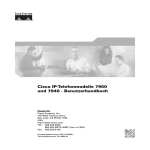
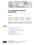
Cisco 7100 Series Routers Slot Numbering
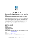
The ISM can be installed in service module slot 5 in Cisco 7120 series and Cisco 7140 series routers.
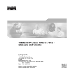
Figure 1-1 shows a Cisco 7120 with an ISM installed in slot 5. Figure 1-2 shows a Cisco 7140 with an
ISM installed in slot 5. A port adapter can be installed in slot 3 in the Cisco 7120 series routers and in
slot 4 in the Cisco 7140 series routers.
Integrated Services Adapter and Integrated Services Module Installation and Configuration
1-4
OL-3575-01 B0
Chapter 1
Overview
Port Adapter Slot Locations on the Supported Platforms
Note
The Cisco 7100 series VPN routers do not support an ISM and an ISA in the same chassis.
Figure 1-1
Service Module Slot 5 in the Cisco 7100 Series Router—Cisco 7120 Series
Port adapter in slot 3
ISM in slot 5
SM-ISM
RESET
BOOT
ERROR
PWR
SLOT 0 SLOT 1
ACT ACT
EN
0
5
FE 0 / 0
EN
TX
FE
0/1
CONS
AUX
SYS
RDY
RX
RX
3775
I
E3
LNK LNK
0
1
2
CEL CAR ALM
7120 - AE3
Figure 1-2
Service Module Slot 5 in the Cisco 7100 Series Router—Cisco 7140 Series
Slot 5
Slot 3
Slot 4
AC OK
DC OK
OTF
RESET
PWR
ACT ACT
EN
5
0
FE 0 / 0
I
SLOT 1
EN
RX
RX
155 - MM
TX
EN
CEL CAR ALM
FE 0 / 1
RX
LNK LNK
0
1
CONS
155 - MM
RX
TX
AC OK
SYS
RDY
DC OK
OTF
2
CEL CAR ALM
Slot 1
AUX
Slot 0
7140 - 2MM3
18499
SM-ISM
SLOT 0
BOOT
ERROR
Slot 2
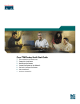
Cisco 7200 Series Routers Slot Numbering
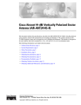
The ISA can be installed in the Cisco 7200 series routers in any available port adapter slot. Figure 1-3
shows a Cisco 7206 with port adapters installed, and a port adapter filler installed in slot 5. (The
Cisco 7202 and Cisco 7204 are not shown; however, the ISA can be installed in any available
port adapter slot.)
Integrated Services Adapter and Integrated Services Module Installation and Configuration
OL-3575-01 B0
1-5
Chapter 1
Overview
LEDs
Figure 1-3
Port Adapter Slots in the Cisco 7206
3
2
1
0
6
TOKEN RING
5
FAST ETHERNET
4
K
RJ4
LIN
0
MII
5
D
EN
AB
LE
3
3
2
2
1
0
LINK
1
0
3
EN
AB
LE
D
ETHERNET 10BT
2
TX
RX
4
TX
RX
3
TX
RX
0
T
O
T
M N
E
SL
EJ
EC
IA
M
C
PC
EN
AB
LE
D
0
R
II
Port adapter slot 5
Port adapter slot 3
Port adapter slot 1
5
J-4
R EN
R
5
PW
J-4
R INK O K
1 O
L
28329
M
II
5
J-4
FE
O
T
SL
2
FAST ETHERNET INPUT/OUTPUT CONTROLLER
1
Cisco 7200
Series
TX
RX
1
TX
RX
1
0
7
6
5
4
3
2
1
0
EN
EN
ETHERNET-10BFL
SERIAL-V.35
Port adapter slot 6
Port adapter slot 4
Port adapter slot 2
Port adapter slot 0
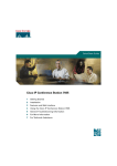
LEDs
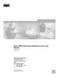
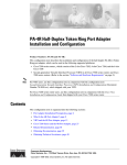
The ISA has three LEDs, as shown in Figure 1-4. Table 1-2 lists the colors and functions of the ISA
LEDs.
Note
The Boot LED remains lit when the ISA/ISM is configured for MPPE, and it starts to pulsate after
booting when the ISA/ISM is configured for IPSec. The ISA/ISM functions normally whether the Boot
LED is pulsating or is solid. See Chapter 4, “Configuring the ISA and ISM” for more information on
configuring the ISA/ISM.
Integrated Services Adapter and Integrated Services Module Installation and Configuration
1-6
OL-3575-01 B0
Chapter 1
Overview
LEDs
Figure 1-4
ISA Front Panel LEDs (SA-ISA shown)
ENCRYPT/COMP
SA-ISA
LE
AB
EN
OT
R
RO
ER
17607
BO
Table 1-2
ISA LEDs
LED Label
Color
State
Function
ENABLE
Green
On
Indicates the ISA is powered up and enabled for
operation.
BOOT
Amber
Pulses1
Indicates the ISA is operating.
On
Indicates the ISA is booting or a packet is being
encrypted or decrypted.
On
Indicates an encryption error has occurred.
ERROR
Amber
This LED is normally off.
1. After successfully booting, the boot LED pulses in a “heartbeat” pattern to indicate that the ISA is operating. As
crypto traffic increases, the nominal level of this LED increases in proportion to the traffic level.
The following conditions must all be met before the enabled LED goes on:
•
The ISA is correctly connected to the backplane and receiving power.
•
The system bus recognizes the ISA.
If either of these conditions is not met, or if the router initialization fails, the enabled LED does not go
on.
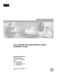
The ISM has three LEDs, as shown in Figure 1-5. Table 1-3 lists the colors and functions of the LEDs.
ISM LEDs
SM-ISM
RESET
BOOT
ERROR
EN
Note
23774
Figure 1-5
The physical orientation of the ISM LEDs is reversed from that of the ISA (see Figure 1-5).
Integrated Services Adapter and Integrated Services Module Installation and Configuration
OL-3575-01 B0
1-7
Chapter 1
Overview
LEDs
Table 1-3
ISM LEDs
LED Label
Color
State
Function
EN
Green
On
Indicates the ISM is powered up and enabled for
operation.
BOOT
Amber
Pulses1
Indicates the ISM is operating.
On
Indicates the ISM is booting or a packet is being
encrypted or decrypted.
On
Indicates an encryption error has occurred. This
LED is normally off.
ERROR
Amber
1. After successfully booting, the boot LED pulses in a “heartbeat” pattern to indicate that the ISM is operating. As
crypto traffic increases, the nominal level of this LED increases in proportion to the traffic level.
The following conditions must all be met before the enabled LED goes on:
•
The ISM is correctly connected to the backplane and receiving power.
•
The system bus recognizes the ISM.
If either of these conditions is not met, or if the router initialization fails for other reasons, the enabled
LED does not go on.
Integrated Services Adapter and Integrated Services Module Installation and Configuration
1-8
OL-3575-01 B0
C H A P T E R
2
Preparing for Installation
This chapter describes the general equipment, safety, and site preparation requirements for installing the
ISA and the ISM.
This chapter contains the following sections:
•
Required Tools and Equipment, page 2-1
•
Software and Hardware Requirements and Compatibility, page 2-1
•
Software Compatibility, page 2-2
•
Safety Guidelines, page 2-3
•
Compliance with U.S. Export Laws and Regulations Regarding Encryption, page 2-6
Required Tools and Equipment
You need the following tools and parts to install an ISA or ISM. If you need additional equipment,
contact a service representative for ordering information.
•
SA-ISA(=) service adapter or SM-ISM(=) service module
•
Number 2 Phillips screwdriver
•
Your own electrostatic discharge (ESD)-prevention equipment or the disposable grounding wrist
strap included with all upgrade kits, field-replaceable units (FRUs), and spares
•
Antistatic mat
•
Antistatic container
Software and Hardware Requirements and Compatibility
Table 2-1 lists the recommended minimum Cisco IOS software release required to use the ISA/ISM in
supported router or switch platforms.
Note
The Cisco 7100 series VPN routers do not support an ISM and an ISA in the same chassis. The
Cisco 7200 series routers do not support the ISM.
The ISA and the ISM are the same board, but differ in their outside appearance.
Integrated Services Adapter and Integrated Services Module Installation and Configuration
OL-3575-01 B0
2-1
Chapter 2
Preparing for Installation
Software and Hardware Requirements and Compatibility
Note
Table 2-1
The Cisco IOS Release 12.1 Mainline does not support the ISA/ISM.
Minimum Cisco IOS Software Releases
Platform
Recommended Minimum Cisco IOS Release
Cisco 7100 series
Cisco IOS Release 12.0(5)XE or a later release of Cisco IOS Release 12.0 XE
•
Cisco 7120 series and
Cisco 7140 series
Cisco IOS Release 12.1(1)E or a later release of Cisco IOS Release 12.1 E
Cisco IOS Release 12.2(2)T or later release of Cisco IOS Release 12.1T
Cisco IOS Release 12.2M or later release of Cisco Release 12.2M.
Cisco 7200 series (for ISA only)
•
Cisco 7202, Cisco 7204, and
Cisco 7206
Cisco IOS Release 12.0(5)XE or a later release of Cisco IOS Release 12.0 XE
Cisco IOS Release 12.1(1)E or a later release of Cisco IOS Release 12.1 E
Cisco IOS Release 12.2(2)T or a later release of Cisco IOS Release 12.1 T
Cisco IOS Release 12.2M or a later release of Cisco IOS Release 12.2M
Cisco IOS Release 12.2(4)B or a later release of Cisco IOS Release 12.2 B
Software Compatibility
To check the minimum software requirements of Cisco IOS software with the hardware installed on your
router, Cisco maintains the Software Advisor tool on Cisco.com. Registered Cisco Direct users can
access the Software Advisor at:http://www.cisco.com/cgi-bin/Support/CompNav/Index.pl. This tool does
not verify whether modules within a system are compatible, but it does provide the minimum Cisco IOS
software requirements for individual hardware modules or components.
Note
Access to this tool is limited to users with Cisco.com login accounts.
Interoperability Between ISA/ISM and VAM
Note
The Cisco 7100 series routers support ISM and the SA-VAM; the Cisco 7200 series routers support ISA
and SA-VAM; and the Cisco 7200 series routers support two ISAs in the same chassis.
Table 2-2 describes the interoperability between ISA and VAM. You can use ISA with VAM, provided
you observe the following conditions:
•
The system supports two ISAs in the same Cisco7200 series router chassis. If one ISA is enabled at
system bootup, and a second ISA is added later, the second ISA becomes active immediately, and
depending on the configuration, the system attempts to load-balance between the two ISAs.
•
If ISA and VAM are in the chassis at system bootup, the Cisco 7200 series router supports the newer
version, in this case, VAM, provided the Cisco IOS Release supports VAM; and the ISA remains
inactive.
Integrated Services Adapter and Integrated Services Module Installation and Configuration
2-2
OL-3575-01 B0
Chapter 2
Preparing for Installation
Safety Guidelines
•
If ISA and VAM are in the chassis at system bootup, and the encryption mppe command is in the
router’s running configuration, then both ISA and VAM are enabled at system bootup. The ISA card
supports MPPE, and the VAM supports ISAKMP/IPSec. You can enable encryption mppe by
following the steps in “Configuring IPSec” section on page 4-4. To disable MPPE on an ISA card,
use the no encryption mppe command. This disables the ISA.
•
To disable a card, use the no crypto engine accelerator type slot/port (port-adapter-slot-number/
interface-port-number) command.
Table 2-2
Interoperability Between ISA and VAM
ISA and ISA
ISA with VAM
•
Supports MPPE
•
Supports MPPE
•
Supports ISAKMP/IPSec
•
Supports ISAKMP/IPSec
•
If two ISAs are enabled in the chassis at
power up, then both modules support both
MPPE and ISAKMP/IPSec.
•
If ISA and VAM are enabled in the chassis at
power up, ISA is used for MPPE, and VAM is
used for ISAKMP/IPSec, provided the
router’s running configuration includes the
encryption mppe command.
•
If ISA is enabled in the chassis at bootup, and
another ISA is added later, the second ISA
immediately becomes active and depending
on the configuration, the system attempts to
load-balance between the two ISAs.
•
If ISA is enabled in the chassis at bootup, and
VAM is added later, the VAM remains
inactive until the next reboot, or until the
configuration is changed to enable the VAM.
Safety Guidelines
This section provides safety guidelines that you should follow when working with any equipment that
connects to electrical power or telephone wiring.
Safety Warnings
Safety warnings appear throughout this publication in procedures that, if performed incorrectly, might
harm you. A warning symbol precedes each warning statement.
Integrated Services Adapter and Integrated Services Module Installation and Configuration
OL-3575-01 B0
2-3
Chapter 2
Preparing for Installation
Safety Guidelines
Warning
This warning symbol means danger. You are in a situation that could cause bodily injury. Before you
work on any equipment, be aware of the hazards involved with electrical circuitry and be familiar
with standard practices for preventing accidents. To see translations of the warnings that appear in
this publication, refer to the Regulatory Compliance and Safety Information document that
accompanied this device.
Waarschuwing
Dit waarschuwingssymbool betekent gevaar. U verkeert in een situatie die lichamelijk letsel kan
veroorzaken. Voordat u aan enige apparatuur gaat werken, dient u zich bewust te zijn van de bij
elektrische schakelingen betrokken risico's en dient u op de hoogte te zijn van standaard
maatregelen om ongelukken te voorkomen. Voor vertalingen van de waarschuwingen die in deze
publicatie verschijnen, kunt u het document Regulatory Compliance and Safety Information
(Informatie over naleving van veiligheids- en andere voorschriften) raadplegen dat bij dit toestel is
ingesloten.
Varoitus
Tämä varoitusmerkki merkitsee vaaraa. Olet tilanteessa, joka voi johtaa ruumiinvammaan. Ennen
kuin työskentelet minkään laitteiston parissa, ota selvää sähkökytkentöihin liittyvistä vaaroista ja
tavanomaisista onnettomuuksien ehkäisykeinoista. Tässä julkaisussa esiintyvien varoitusten
käännökset löydät laitteen mukana olevasta Regulatory Compliance and Safety Information
-kirjasesta (määräysten noudattaminen ja tietoa turvallisuudesta).
Attention
Ce symbole d'avertissement indique un danger. Vous vous trouvez dans une situation pouvant causer
des blessures ou des dommages corporels. Avant de travailler sur un équipement, soyez conscient
des dangers posés par les circuits électriques et familiarisez-vous avec les procédures couramment
utilisées pour éviter les accidents. Pour prendre connaissance des traductions d’avertissements
figurant dans cette publication, consultez le document Regulatory Compliance and Safety
Information (Conformité aux règlements et consignes de sécurité) qui accompagne cet appareil.
Warnung
Dieses Warnsymbol bedeutet Gefahr. Sie befinden sich in einer Situation, die zu einer
Körperverletzung führen könnte. Bevor Sie mit der Arbeit an irgendeinem Gerät beginnen, seien Sie
sich der mit elektrischen Stromkreisen verbundenen Gefahren und der Standardpraktiken zur
Vermeidung von Unfällen bewußt. Übersetzungen der in dieser Veröffentlichung enthaltenen
Warnhinweise finden Sie im Dokument Regulatory Compliance and Safety Information
(Informationen zu behördlichen Vorschriften und Sicherheit), das zusammen mit diesem Gerät
geliefert wurde.
Avvertenza
Advarsel
Questo simbolo di avvertenza indica un pericolo. La situazione potrebbe causare infortuni alle
persone. Prima di lavorare su qualsiasi apparecchiatura, occorre conoscere i pericoli relativi ai
circuiti elettrici ed essere al corrente delle pratiche standard per la prevenzione di incidenti. La
traduzione delle avvertenze riportate in questa pubblicazione si trova nel documento Regulatory
Compliance and Safety Information (Conformità alle norme e informazioni sulla sicurezza) che
accompagna questo dispositivo.
Dette varselsymbolet betyr fare. Du befinner deg i en situasjon som kan føre til personskade. Før du
utfører arbeid på utstyr, må du vare oppmerksom på de faremomentene som elektriske kretser
innebærer, samt gjøre deg kjent med vanlig praksis når det gjelder å unngå ulykker. Hvis du vil se
oversettelser av de advarslene som finnes i denne publikasjonen, kan du se i dokumentet Regulatory
Compliance and Safety Information (Overholdelse av forskrifter og sikkerhetsinformasjon) som ble
levert med denne enheten.
Integrated Services Adapter and Integrated Services Module Installation and Configuration
2-4
OL-3575-01 B0
Chapter 2
Preparing for Installation
Safety Guidelines
Aviso
Este símbolo de aviso indica perigo. Encontra-se numa situação que lhe poderá causar danos
físicos. Antes de começar a trabalhar com qualquer equipamento, familiarize-se com os perigos
relacionados com circuitos eléctricos, e com quaisquer práticas comuns que possam prevenir
possíveis acidentes. Para ver as traduções dos avisos que constam desta publicação, consulte o
documento Regulatory Compliance and Safety Information (Informação de Segurança e Disposições
Reguladoras) que acompanha este dispositivo.
¡Advertencia!
Este símbolo de aviso significa peligro. Existe riesgo para su integridad física. Antes de manipular
cualquier equipo, considerar los riesgos que entraña la corriente eléctrica y familiarizarse con los
procedimientos estándar de prevención de accidentes. Para ver una traducción de las advertencias
que aparecen en esta publicación, consultar el documento titulado Regulatory Compliance and
Safety Information (Información sobre seguridad y conformidad con las disposiciones
reglamentarias) que se acompaña con este dispositivo.
Varning!
Denna varningssymbol signalerar fara. Du befinner dig i en situation som kan leda till personskada.
Innan du utför arbete på någon utrustning måste du vara medveten om farorna med elkretsar och
känna till vanligt förfarande för att förebygga skador. Se förklaringar av de varningar som förkommer
i denna publikation i dokumentet Regulatory Compliance and Safety Information (Efterrättelse av
föreskrifter och säkerhetsinformation), vilket medföljer denna anordning.
.
Electrical Equipment Guidelines
Follow these basic guidelines when working with any electrical equipment:
•
Before beginning any procedures requiring access to the chassis interior, locate the emergency
power-off switch for the room in which you are working.
•
Disconnect all power and external cables before moving a chassis.
•
Do not work alone when potentially hazardous conditions exist.
•
Never assume that power has been disconnected from a circuit; always check.
•
Do not perform any action that creates a potential hazard to people or makes the equipment unsafe;
carefully examine your work area for possible hazards such as moist floors, ungrounded power
extension cables, and missing safety grounds.
Preventing Electrostatic Discharge Damage
Electrostatic discharge (ESD) damage, which can occur when electronic cards or components are
improperly handled, results in complete or intermittent failures. Port adapters and processor modules
comprise printed circuit boards that are fixed in metal carriers. Electromagnetic interference (EMI)
shielding and connectors are integral components of the carrier. Although the metal carrier helps to
protect the board from ESD, use a preventive antistatic strap during handling.
Following are guidelines for preventing ESD damage:
•
Always use an ESD wrist or ankle strap and ensure that it makes good skin contact.
•
Connect the equipment end of the strap to an unfinished chassis surface.
Integrated Services Adapter and Integrated Services Module Installation and Configuration
OL-3575-01 B0
2-5
Chapter 2
Preparing for Installation
Compliance with U.S. Export Laws and Regulations Regarding Encryption
Caution
•
When installing a component, use any available ejector levers or captive installation screws to
properly seat the bus connectors in the backplane or midplane. These devices prevent accidental
removal, provide proper grounding for the system, and help to ensure that bus connectors are
properly seated.
•
When removing a component, use any available ejector levers or captive installation screws to
release the bus connectors from the backplane or midplane.
•
Handle carriers by available handles or edges only; avoid touching the printed circuit boards or
connectors.
•
Place a removed board component-side-up on an antistatic surface or in a static shielding container.
If you plan to return the component to the factory, immediately place it in a static shielding
container.
•
Avoid contact between the printed circuit boards and clothing. The wrist strap only protects
components from ESD voltages on the body; ESD voltages on clothing can still cause damage.
•
Never attempt to remove the printed circuit board from the metal carrier.
For safety, periodically check the resistance value of the antistatic strap. The measurement should be
between 1 and 10 megohms (Mohm).
Compliance with U.S. Export Laws and Regulations Regarding
Encryption
This product performs encryption and is regulated for export by the U.S. government. Persons exporting
any item out of the United States by either physical or electronic means must comply with the Export
Administration Regulations as administered by the U.S. Department of Commerce, Bureau of Export
Administration. See http://www.bxa.doc.gov/ for more information.
Certain “strong” encryption items can be exported outside the United States depending upon the
destination, end user, and end use. See http://www.cisco.com/wwl/export/crypto/ for more information
about Cisco-eligible products, destinations, end users, and end uses.
Check local country laws prior to export to determine import and usage requirements as necessary. See
http://www.kub.nl/faculteiten/frw/outdated.html as one possible, unofficial source of international
encryption laws.
Integrated Services Adapter and Integrated Services Module Installation and Configuration
2-6
OL-3575-01 B0
C H A P T E R
3
Removing and Installing the ISA and the ISM
This chapter describes how to remove the ISA or ISM from supported platforms and also how to install
a new or replacement ISA or ISM. This chapter contains the following sections:
•
Handling the ISA or the ISM, page 3-1
•
Online Insertion and Removal, page 3-2
•
Warnings and Cautions, page 3-3
•
ISA or ISM Removal and Installation, page 3-4
The ISA and the ISM circuit boards are mounted to metal carriers and are sensitive to electrostatic
discharge (ESD) damage.
Note
Caution
When a port adapter slot or service module slot is not in use, a blank port adapter or service module must
fill the empty slot to allow the router to conform to electromagnetic interference (EMI) emissions
requirements and to allow proper airflow. If you plan to install a new ISA or ISM in a slot that is not in
use, you must first remove the blank port adapter or blank service module.
When powering off the router, wait a minimum of 30 seconds before powering it on again.
Handling the ISA or the ISM
Caution
Always handle the ISA or the ISM by the carrier edges and handle; never touch the components or
connector pins. (See Figure 3-1 and Figure 3-2.)
Integrated Services Adapter and Integrated Services Module Installation and Configuration
OL-3575-01 B0
3-1
Chapter 3
Removing and Installing the ISA and the ISM
Online Insertion and Removal
Figure 3-1
Handling the ISM
Printed circuit board
23778
Metal carrier
Figure 3-2
Handling the ISA
Metal carrier
H6420
Printed circuit board
Online Insertion and Removal
Several platforms support online insertion and removal (OIR); therefore, you do not have to power down
the router when removing and replacing an ISA on Cisco 7200 series routers.
Warning
Cisco 7100 series routers do not support OIR for the service module slot (slot 5); therefore, you must
power down the router when removing or replacing an ISM in Cisco 7100 series routers.
It is wise to gracefully shut down the system before removing a port adapter that has active traffic moving
through it. Removing a module while traffic is flowing through the ports can cause system disruption.
Once the module is inserted, the ports can be brought back up.
Note
As you disengage the module from the router or switch, online insertion and removal (OIR)
administratively shuts down all active interfaces in the module.
OIR allows you to install and replace modules while the router is operating; you do not need to notify
the software or shut down the system power, although you should not run traffic through the module you
are removing while it is being removed. OIR is a method that is seamless to end users on the network,
maintains all routing information, and preserves sessions.
The following is a functional description of OIR for background information only; for specific
procedures for installing and replacing a module in a supported platform, refer to the “ISA or ISM
Removal and Installation” section on page 3-4.
Integrated Services Adapter and Integrated Services Module Installation and Configuration
3-2
OL-3575-01 B0
Chapter 3
Removing and Installing the ISA and the ISM
Warnings and Cautions
Each module has a bus connector that connects it to the router. The connector has a set of tiered pins in
three lengths that send specific signals to the system as they make contact with the module. The system
assesses the signals it receives and the order in which it receives them to determine if a module is being
removed from or introduced to the system. From these signals, the system determines whether to
reinitialize a new interface or to shut down a disconnected interface.
Specifically, when you insert a module, the longest pins make contact with the module first, and the
shortest pins make contact last. The system recognizes the signals and the sequence in which it receives
them.
When you remove or insert a module, the pins send signals to notify the system of changes. The router
then performs the following procedure:
Note
1.
Rapidly scans the system for configuration changes.
2.
Initializes newly inserted port adapters or administratively shuts down any vacant interfaces.
3.
Brings all previously configured interfaces on the module back to their previously installed state.
Any newly inserted interface is put in the administratively shutdown state, as if it was present (but
not configured) at boot time. If a similar module type is reinserted into a slot, its ports are configured
and brought online up to the port count of the originally installed module of that type.
Before you begin installation, read Chapter 2, “Preparing for Installation,” for a list of parts and tools
required for installation.
Warnings and Cautions
Observe the following warnings and cautions when installing or removing service adapters and service
modules.
Note
If a port adapter lever or other retaining mechanism does not move to the locked position, the service
adapter is not completely seated in the midplane. Carefully pull the service adapter out of the slot,
reinsert it, and move the port adapter lever or other mechanism to the locked position.
Caution
To prevent jamming the carrier between the upper and the lower edges of the service module slot, and to
ensure that the edge connector at the rear of the ISM mates with the connection at the rear of the service
module slot, make certain that the carrier is positioned correctly, as shown in the cutaway in the “Cisco
7100 Series—Removing and Installing the ISM” section on page 3-5
Warning
When performing the following procedures, wear a grounding wrist strap to avoid ESD damage to the
card. Some platforms have an ESD connector for attaching the wrist strap. Do not directly touch the
midplane or backplane with your hand or any metal tool, or you could shock yourself.
Warning
Cisco 7100 series routers do not support OIR of the ISM. Failure to power down the router when
removing or replacing the ISM could cause serious equipment damage or electrical shock.
Integrated Services Adapter and Integrated Services Module Installation and Configuration
OL-3575-01 B0
3-3
Chapter 3
Removing and Installing the ISA and the ISM
ISA or ISM Removal and Installation
ISA or ISM Removal and Installation
In this section, the illustrations that follow give step-by-step instructions on how to remove and install
the ISA or the ISM. This section contains the following illustrations:
Note
•
Cisco 7100 Series—Removing and Installing the ISM, page 3-5
•
Cisco 7200 Series—Removing and Installing the ISA, page 3-6
The Cisco 7100 series VPN routers do not support an ISM and an ISA in the same chassis.
Integrated Services Adapter and Integrated Services Module Installation and Configuration
3-4
OL-3575-01 B0
Chapter 3
Removing and Installing the ISA and the ISM
ISA or ISM Removal and Installation
Cisco 7100 Series—Removing and Installing the ISM
Step 1
To remove the ISM, use a number 2 Phillips screwdriver to
loosen the captive installation screws.
Step 2
Grasp the captive installation screws of the ISM to pull it from the
router.
Captive installation screws
Note: When inserting the ISM, hold the ISM up at a
slight angle to engage the carrier guides. Completely
seating the ISM in the slot may require several attempts.
5
SM-ISM
EN
I
TD
RESET
BOOT
ERROR
EN
TC
RD
RC
LB
CD
TD
TC
RD
RC
LB
CD
TD
TC
RD
RC
LB
CD
TD
TC
RD
RC
LB
CD
Step 3
To insert the ISM, carefully align the ISM carrier between the
upper and the lower edges of the service module slot (slot 5).
ISM in slot 5
Step 4
Step 5
After the ISM is properly seated, tighten the captive installation
screws.
29332
Carefully slide the ISM all the way into the slot until it is seated in
the router midplane.
Integrated Services Adapter and Integrated Services Module Installation and Configuration
OL-3575-01 B0
3-5
Chapter 3
Removing and Installing the ISA and the ISM
ISA or ISM Removal and Installation
Cisco 7200 Series—Removing and Installing the ISA
Step 1
Port adapter lever
(locked position)
To remove the service adapter,
place the port adapter lever in the
unlocked position. (See A.) The
port adapter lever remains in the
unlocked position.
3
2
1
0
6
TOKEN RING
Step 2
5
4
NK
0
LI
MII
K
3
3
2
2
LIN
1
0
D
1
0
LE
AB
EN
3
A
EN
AB
LE
D
ETHERNET 10BT
Grasp the handle of the service
adapter and pull the service adapter
from the router. If you are removing
a blank port adapter, pull the blank
port adapter completely out of the
chassis slot.
RJ
45
FAST ETHERNET
2
CD
LB
RC
RD
TC
TD
CD
LB
RC
RD
TC
TD
CD
LB
RC
RD
TC
TD
CD
LB
RC
RD
TC
TD
EN
FAST SERIAL
1
FAST ETHERNET INPUT/OUTPUT CONTROLLER
RE
U
Note: This adapter
removal applies to any
port or service adapter.
Step 3
To insert the service adapter,
carefully align the service adapter
carrier between the upper and the
lower edges of the port adapter slot.
(See B.)
PW
O
K R
1O
R
LI J4
N 5
K
R
EN J4
5
M
EN II
0
SLO
T
PC
M
C
IA
EJE
C
T
EN
AB
LE
D
0
RJ
FE
-4
CP
5
M
II
SLO
T
1
SE
T
Cisco 7200
Series
Port adapter lever
(unlocked position)
Step 4
Carefully slide the new service
adapter into the port adapter slot
until the service adapter is seated in
the router midplane.
2
1
0
6
3
TOKEN RING
Slot
guide
5
FAST ETHERNET
4
45
RJ
LI
MII
2
0
EN
3
2
NK
D
LE
AB
K
1
0
LIN
3
2
0
D
3
After the service adapter is properly
seated, lock the port adapter lever.
(See A.)
EN
AB
LE
1
ETHERNET 10BT
CP
5
-4
RJ
T
SE
U
RE
II
T
M
FE
FAST ETHERNET INPUT/OUTPUT CONTROLLER
AB
LE
D
SLO
1
1
29339
PW
K R
O
1O
R
LI J4
N 5
K
5
B
R
EN J4
M
EN II
T
0
T
C
EJE
SLO
PC
M
C
IA
Cisco 7200
Series
EN
Step 5
Integrated Services Adapter and Integrated Services Module Installation and Configuration
3-6
OL-3575-01 B0
C H A P T E R
4
Configuring the ISA and ISM
This chapter contains the information and procedures needed to configure the ISA or the ISM in the
Cisco 7100 series VPN routers and Cisco 7200 series routers. This chapter contains the following
sections:
•
Overview, page 4-1
•
Using the EXEC Command Interpreter, page 4-2
•
Enabling MPPE, page 4-2
•
Configuring IKE, page 4-3
•
Configuring IPSec, page 4-4
•
Creating Crypto Maps, page 4-7
•
Applying Crypto Maps to Interfaces, page 4-9
•
Verifying Configuration, page 4-9
•
IPSec Example, page 4-12
Overview
On power up if the enabled LED is on, the ISA or the ISM is fully functional and does not require any
configuration commands. However, for the ISA or the ISM to provide encryption services, you must
complete the steps in the following sections:
•
Enabling MPPE, page 4-2 (required)
•
Configuring IKE, page 4-3 (required)
•
Configuring IPSec, page 4-4 (required)
•
Creating Crypto Maps, page 4-7 (required)
Optionally, you can configure Certification Authority (CA) interoperability (refer to the “Configuring
Certification Authority Interoperability” chapter in the Security Configuration Guide publication).
The ISA or the ISM provides encryption services for any interface in Cisco 7100 series and Cisco 7200
series routers. If you have previously configured IPSec on the router and you install an ISA or an ISM,
the ISA or the ISM automatically performs encryption services.
Note
There are no interfaces to configure on the ISA or the ISM.
Integrated Services Adapter and Integrated Services Module Installation and Configuration
OL-3575-01 B0
4-1
Chapter 4
Configuring the ISA and ISM
Using the EXEC Command Interpreter
Configuring IPSec requires privileged-level access to the EXEC command interpreter. Also,
privileged-level access usually requires a password. (Contact your system administrator, if necessary, to
obtain privileged-level access.)
These sections contain basic configuration information only. For detailed configuration information,
refer to the “IP Security and Encryption” chapter of the Security Configuration Guide publication.
Using the EXEC Command Interpreter
You modify the configuration of your router through the software command interpreter called the EXEC
(also called enable mode). You must enter the privileged level of the EXEC command interpreter with
the enable command before you can use the configure command to configure a new interface or change
the existing configuration of an interface. The system prompts you for a password if one has been set.
The system prompt for the privileged level ends with a pound sign (#) instead of an angle bracket (>).
At the console terminal, use the following procedure to enter the privileged level:
Step 1
At the user-level EXEC prompt, enter the enable command. The EXEC prompts you for a
privileged-level password as follows:
Router> enable
Password:
Step 2
Enter the password (the password is case sensitive). For security purposes, the password is not displayed.
When you enter the correct password, the system displays the privileged-level system prompt (#):
Router#
Enabling MPPE
Use the encryption mppe command in ISA controller configuration mode to enable MPPE on the ISA
or the ISM. This off-loads the MPPE function from the route processor to the ISA or the ISM.
Note
The boot LED remains lit instead of pulsating when the ISA/ISM is configured for IPSec (default). When
the ISA/ISM is configured for MPPE, the Boot LED pulsates. The ISA/ISM functions normally whether
the Boot LED is pulsating or is solid.
Note
To use the encryption mppe command, PPP encapsulation must be enabled.
Step
Command
Purpose
slot/port
1.
Router(config)# controller isa
2.
Router(config-controller)# encryption mppe
Enter controller configuration mode on
the ISA card.
Enables MPPE encryption.
Integrated Services Adapter and Integrated Services Module Installation and Configuration
4-2
OL-3575-01 B0
Chapter 4
Configuring the ISA and ISM
Configuring IKE
Use the ppp encrypt mppe{auto | 40 | 128} [passive | required] [stateful] command in interface
configuration mode to enable MPPE on the virtual template.
Configuring IKE
IKE is enabled by default. IKE does not have to be enabled for individual interfaces but is enabled
globally for all interfaces at the router. You must create IKE policies at each peer. An IKE policy defines
a combination of security parameters to be used during the IKE negotiation.
You can create multiple IKE policies, each with a different combination of parameter values. If you do
not configure any IKE policies, the router uses the default policy, which is always set to the lowest
priority, and which contains each parameter’s default value.
For each policy that you create, you assign a unique priority (1 through 10,000, with 1 being the highest
priority). You can configure multiple policies on each peer—but at least one of these policies must
contain exactly the same encryption, hash, authentication, and Diffie-Hellman parameter values as one
of the policies on the remote peer.
If you do not specify a value for a parameter, the default value is assigned. For information on default
values, refer to the “IP Security and Encryption” chapter of the Security Command Reference
publication.
Note
The default policy and the default values for configured policies do not show up in the configuration
when you issue a show running-config EXEC command. Instead, to see the default policy and any
default values within configured policies, use the show crypto isakmp policy EXEC command.
To configure a policy, use the following commands, starting in global configuration mode:
Step
Command
Purpose
1.
crypto isakmp policy priority
Identify the policy to create, and enter
config-isakmp command mode.
1.
encryption {des | 3des}
Specify the encryption algorithm.
1.
group {1 | 2}
Specify the Diffie-Hellman group identifier.
For detailed information on creating IKE policies, refer to the “Configuring Internet Key Exchange
Security Protocol” chapter in the Security Configuration Guide publication. This chapter contains
information on the following topics:
•
Why Do You Need to Create These Policies?
•
What Parameters Do You Define in a Policy?
•
How Do IKE Peers Agree upon a Matching Policy?
•
Which Value Should You Select for Each Parameter?
•
Creating Policies
•
Additional Configuration Required for IKE Policies
Integrated Services Adapter and Integrated Services Module Installation and Configuration
OL-3575-01 B0
4-3
Chapter 4
Configuring the ISA and ISM
Configuring IPSec
Configuring IPSec
After you have completed IKE configuration, configure IPSec at each participating IPSec peer. This
section contains basic steps to configure IPSec and includes the tasks discussed in the following sections:
•
Creating Crypto Access Lists, page 4-4
•
Defining a Transform Set, page 4-5
For detailed information on configuring IPSec, refer to the “Configuring IPSec Network Security”
chapter in the Security Configuration Guide publication. This chapter contains information on the
following topics:
•
Ensure Access Lists Are Compatible with IPSec
•
Set Global Lifetimes for IPSec Security Associations
•
Create Crypto Access Lists
•
Define Transform Sets
•
Create Crypto Map Entries
•
Apply Crypto Map Sets to Interfaces
•
Monitor and Maintain IPSec
Creating Crypto Access Lists
Crypto access lists are used to define which IP traffic will be protected by encryption and which will not.
(These access lists are not the same as regular access lists, which determine what traffic to forward or
block at an interface.) For example, access lists can be created to protect all IP traffic between subnet A
and subnet Y or Telnet traffic between host A and host B.
The access lists themselves are not specific to IPSec—they are no different from what is used for Cisco
Encryption Technology (CET). It is the crypto map entry referencing the specific access list that defines
whether IPSec or CET processing is applied to the traffic matching a permit entry in the access list.
Crypto access lists associated with IPSec crypto map entries have four primary functions:
•
Select outbound traffic to be protected by IPSec (permit = protect).
•
Indicate the data flow to be protected by the new security associations (specified by a single permit
entry) when initiating negotiations for IPSec security associations.
•
Process inbound traffic in order to filter out and discard traffic that should have been protected by
IPSec.
•
Determine whether or not to accept requests for IPSec security associations on behalf of the
requested data flows when processing IKE negotiation from the IPSec peer. (Negotiation is only
done for ipsec-isakmp crypto map entries.) In order to be accepted, if the peer initiates the IPSec
negotiation, it must specify a data flow that is “permitted” by a crypto access list associated with an
ipsec-isakmp crypto map entry.
If you want certain traffic to receive one combination of IPSec protection (for example, authentication
only) and other traffic to receive a different combination of IPSec protection
(for example, both authentication and encryption), you need to create two different crypto access lists to
define the two different types of traffic. These different access lists are then used in different crypto map
entries that specify different IPSec policies.
Integrated Services Adapter and Integrated Services Module Installation and Configuration
4-4
OL-3575-01 B0
Chapter 4
Configuring the ISA and ISM
Configuring IPSec
Later, you will associate the crypto access lists to particular interfaces when you configure and apply
crypto map sets to the interfaces (following instructions in the section “Creating Crypto Maps” section
on page 4-7).
Note
IKE uses UDP port 500. The IPSec Encapsulation Security Protocol (ESP) and Authentication Header
(AH) protocols use protocol numbers 50 and 51. Ensure that your interface access lists are configured
so that protocol numbers 50, 51, and UDP port 500 traffic are not blocked at interfaces used by IPSec.
In some cases you might need to add a statement to your access lists to explicitly permit this traffic.
To create crypto access lists, use the following commands in global configuration mode:
Step
1.
Command
Purpose
access-list access-list-number {deny |
permit} protocol source source-wildcard
destination destination-wildcard [log]
Specify conditions to determine which IP
packets are protected.1 (Enable or disable
encryption for traffic that matches these
conditions.)
or
ip access-list extended name
2.
Add permit and deny statements as
appropriate.
3.
end
We recommend that you configure “mirror
image” crypto access lists for use by IPSec
and that you avoid using the any keyword.
Exit the configuration command mode.
1. You specify conditions using an IP access list designated by either a number or a name. The access-list command
designates a numbered extended access list; the ip access-list extended command designates a named access list.
For detailed information on configuring access lists, refer to the “Configuring IPSec Network Security”
chapter in the Security Configuration Guide publication. This chapter contains information on the
following topics:
•
Crypto Access List Tips
•
Defining Mirror Image Crypto Access Lists at Each IPSec Peer
•
Using the any Keyword in Crypto Access Lists
Defining a Transform Set
A transform set represents a certain combination of security protocols and algorithms. During the IPSec
security association negotiation, the peers agree to use a particular transform set for protecting a
particular data flow.
You can specify multiple transform sets, and then specify one or more of these transform sets in a crypto
map entry. The transform set defined in the crypto map entry is used in the IPSec security association
negotiation to protect the data flows specified by that crypto map entry’s access list.
During IPSec security association negotiations with IKE, the peers search for a transform set that is the
same at both peers. When such a transform set is found, it is selected and is applied to the protected
traffic as part of both peers’ IPSec security associations.
With manually established security associations, there is no negotiation with the peer, so both sides must
specify the same transform set.
Integrated Services Adapter and Integrated Services Module Installation and Configuration
OL-3575-01 B0
4-5
Chapter 4
Configuring the ISA and ISM
Configuring IPSec
If you change a transform set definition, the change is only applied to crypto map entries that reference
the transform set. The change is not applied to existing security associations but is used in subsequent
negotiations to establish new security associations. If you want the new settings to take effect sooner,
you can clear all or part of the security association database by using the clear crypto sa command.
To define a transform set, use the following commands, starting in global configuration mode:
Step
Command
Purpose
crypto ipsec transform-set
transform-set-name transform1
[transform2 [transform3]]
Define a transform set and enter crypto
transform configuration mode.
2.
mode [tunnel | transport]
Change the mode associated with the
transform set. The mode setting is applicable
only to traffic whose source and destination
addresses are the IPSec peer addresses; it is
ignored for all other traffic. (All other traffic
is in tunnel mode only.)
3.
end
Exit the crypto transform configuration mode
to enabled mode.
4.
clear crypto sa
This step clears existing IPSec security
associations so that any changes to a
transform set take effect on subsequently
established security associations (SAs).
(Manually established SAs are reestablished
immediately.)
1.
or
clear crypto sa peer {ip-address |
peer-name}
or
clear crypto sa map map-name
or
clear crypto sa spi destination-address
protocol spi
Complex rules define which entries you can
use for the transform arguments. These rules
are explained in the command description for
the crypto ipsec transform-set command,
and Table 4-1 on page 4-7 provides a list of
allowed transform combinations.
Using the clear crypto sa command without
parameters clears out the full SA database,
which clears out active security sessions. You
may also specify the peer, map, or entry
keywords to clear out only a subset of the SA
database.
Integrated Services Adapter and Integrated Services Module Installation and Configuration
4-6
OL-3575-01 B0
Chapter 4
Configuring the ISA and ISM
Creating Crypto Maps
Table 4-1 shows allowed transform combinations.
Table 4-1
Allowed Transform Combinations
AH Transform 1
ESP Encryption Transform1
ESP Authentication Transform 2
Transform
Description
Transform
ah-md5-hma AH with MD5
c
(HMAC variant)
authentication
algorithm
esp-3des
ESP with 168-bit Triple
esp-md5-hma
DES encryption algorithm c
ESP with MD5
(HMAC variant)
authentication
algorithm
ah-sha-hmac AH with SHA
(HMAC variant)
authentication
algorithm
esp-des
ESP with 56-bit DES
encryption algorithm
ESP with SHA
(HMAC variant)
authentication
algorithm
esp-null
ESP transform without
cipher
Transform
Description
esp-sha-hmac
Description
1. Pick one transform option.
2. Pick one transform option, but only if you selected esp-null or ESP encryption transform.
Creating Crypto Maps
Crypto map entries created for IPSec pull together the various elements used to set up IPSec security
associations, including:
•
Which traffic should be protected by IPSec (according to a crypto access list)
•
Granularity of the flow to be protected by a set of security associations
•
Where IPSec-protected traffic should be sent (who the remote IPSec peer is)
•
Local address to be used for the IPSec traffic (see the “Applying Crypto Maps to Interfaces” section
on page 4-9 for more details)
•
What IPSec security should be applied to this traffic (selecting from a list of one or more transform
sets)
•
Whether security associations are manually established or are established through IKE
•
Other parameters that might be necessary to define an IPSec security association
Crypto map entries with the same crypto map name (but different map sequence numbers) are grouped
into a crypto map set. Later, you will apply these crypto map sets to interfaces; then, all IP traffic passing
through the interface is evaluated against the applied crypto map set. If a crypto map entry sees outbound
IP traffic that should be protected and the crypto map specifies the use of IKE, a security association is
negotiated with the remote peer according to the parameters included in the crypto map entry; otherwise,
if the crypto map entry specifies the use of manual security associations, a security association should
have already been established through configuration.
(If a dynamic crypto map entry sees outbound traffic that should be protected and no security association
exists, the packet is dropped.)
The policy described in the crypto map entries is used during the negotiation of security associations. If
the local router initiates the negotiation, it uses the policy specified in the static crypto map entries to
create the offer to be sent to the specified IPSec peer. If the IPSec peer initiates the negotiation, the local
router checks the policy from the static crypto map entries, as well as any referenced dynamic crypto
map entries, to decide whether to accept or reject the peer’s request (offer).
Integrated Services Adapter and Integrated Services Module Installation and Configuration
OL-3575-01 B0
4-7
Chapter 4
Configuring the ISA and ISM
Creating Crypto Maps
For IPSec to succeed between two IPSec peers, both peers’ crypto map entries must contain compatible
configuration statements.
When two peers try to establish a security association, each must have at least one crypto map entry that
is compatible with one of the other peer’s crypto map entries. For two crypto map entries to be
compatible, they must meet the following criteria:
•
The crypto map entries must contain compatible crypto access lists (for example, mirror image
access lists). When the responding peer is using dynamic crypto maps, the entries in the local crypto
access list must be “permitted” by the peer’s crypto access list.
•
The crypto map entries must each identify the other peer (unless the responding peer is using
dynamic crypto maps).
•
The crypto map entries must have at least one transform set in common.
When IKE is used to establish security associations, the IPSec peers can negotiate the settings they will
use for the new security associations. This means that you can specify lists (such as lists of acceptable
transforms) within the crypto map entry.
To create crypto map entries that use IKE to establish the security associations, use the following
commands, starting in global configuration mode:
Step
Command
Purpose
1.
crypto map map-name seq-num
ipsec-isakmp
Create the crypto map and enter
crypto map configuration mode.
2.
match address access-list-id
Specify an extended access list. This
access list determines which traffic is
protected by IPSec and which is not.
3.
set peer {hostname | ip-address}
Specify a remote IPSec peer. This is
the peer to which IPSec-protected
traffic can be forwarded.
Repeat for multiple remote peers.
4.
set transform-set transform-set-name1
Specify which transform sets are
[transform-set-name2...transform-set-name6] allowed for this crypto map entry.
List multiple transform sets in order
of priority (highest priority first).
5.
end
Exit crypto map configuration mode.
Repeat these steps to create additional crypto map entries as required.
For detailed information on configuring crypto maps, refer to the “Configuring IPSec Network Security”
chapter in the Security Configuration Guide publication. This chapter contains information on the
following topics:
•
About Crypto Maps
•
Load Sharing
•
How Many Crypto Maps Should You Create?
•
Creating Crypto Map Entries for Establishing Manual Security Associations
•
Creating Crypto Map Entries That Use IKE to Establish Security Associations
•
Creating Dynamic Crypto Maps
Integrated Services Adapter and Integrated Services Module Installation and Configuration
4-8
OL-3575-01 B0
Chapter 4
Configuring the ISA and ISM
Applying Crypto Maps to Interfaces
Applying Crypto Maps to Interfaces
You need to apply a crypto map set to each interface through which IPSec traffic flows. Applying the
crypto map set to an interface instructs the router to evaluate all the interface’s traffic against the crypto
map set and to use the specified policy during connection or security association negotiation on behalf
of traffic to be protected by encryption.
To apply a crypto map set to an interface, use the following commands, starting in global configuration
mode:
Step
Command
Purpose
1.
interface type number
Specify an interface on which to apply the
crypto map and enter interface configuration
mode.
2.
crypto map map-name
Apply a crypto map set to an interface.
3.
end
Exit interface configuration mode.
For redundancy, you could apply the same crypto map set to more than one interface. The default
behavior is as follows:
•
Each interface has its own piece of the security association database.
•
The IP address of the local interface is used as the local address for IPSec traffic originating from
or destined to that interface.
If you apply the same crypto map set to multiple interfaces for redundancy purposes, you need to specify
an identifying interface. This has the following effects:
•
The per-interface portion of the IPSec security association database is established one time and
shared for traffic through all the interfaces that share the same crypto map.
•
The IP address of the identifying interface is used as the local address for IPSec traffic originating
from or destined to those interfaces sharing the same crypto map set.
One suggestion is to use a loopback interface as the identifying interface.
To specify redundant interfaces and name an identifying interface, use the following command in global
configuration mode:
crypto map map-name local-address interface-id
This command permits redundant interfaces to share the same crypto map, using the same local identity.
Verifying Configuration
Certain configuration changes only take effect when subsequent security associations are negotiated. If
you want the new settings to take immediate effect, you must clear the existing security associations so
that they are reestablished with the changed configuration. For manually established security
associations, you must clear and reinitialize the security associations, or the changes do not take effect.
If the router is actively processing IPSec traffic, it is desirable to clear only the portion of the security
association database that would be affected by the configuration changes (that is, clear only the security
associations established by a given crypto map set). Clearing the full security association database
should be reserved for large-scale changes or when the router is processing very little other IPSec traffic.
Integrated Services Adapter and Integrated Services Module Installation and Configuration
OL-3575-01 B0
4-9
Chapter 4
Configuring the ISA and ISM
Verifying Configuration
To clear (and reinitialize) IPSec security associations, use one of the following commands in global
configuration mode:
Command
Purpose
clear crypto sa
Clear IPSec security associations (SAs).
or
Using the clear crypto sa command without
parameters clears out the full SA database,
which clears out active security sessions. You
may also specify the peer, map, or spi keywords
to clear out only a subset of the SA database.
clear crypto sa peer {ip-address | peer-name}
or
clear crypto sa map map-name
or
clear crypto sa spi destination-address
protocol spi
To view information about your IPSec configuration, use one or more of the following commands in
EXEC mode:
Command
Purpose
show crypto ipsec transform-set
View your transform set configuration.
show crypto map [interface interface | tag
map-name]
View your crypto map configuration.
show crypto ipsec sa [map map-name | address View information about IPSec security
| identity | detail | interface]
associations.
show crypto dynamic-map [tag map-name]
View information about dynamic crypto maps.
show crypto ipsec
security-association-lifetime
View global security association lifetime values.
The following is sample output for the show crypto ipsec transform-set command. This command
shows the type of transform set configured on the router.
Router# show crypto ipsec transform-set
Transform set combined-des-md5: {esp-des esp-md5-hmac}
will negotiate = {Tunnel,},
Transform set t1: {esp-des esp-md5-hmac}
will negotiate = {Tunnel,},
Transform set t100: {ah-sha-hmac}
will negotiate = {Transport,},
Transform set t2: {ah-sha-hmac}
will negotiate = {Tunnel,},
{esp-des}
will negotiate = {Tunnel,},
The following is sample output for the show crypto map command. Peer 172.21.114.67 is the IP address
of the remote IPSec peer. Extended IP access list 141 lists the access list associated with the crypto map.
Current peer indicates the current IPSec peer. Security-association lifetime indicates the lifetime of the
security association. PFS N indicates that IPSec does not negotiate perfect forward secrecy when
establishing new security associations for this crypto map. Transform sets indicates the name of the
transform set that can be used with the crypto map.
Router# show crypto map
Crypto Map: “router-alice” idb: Ethernet0 local address: 172.21.114.123
Crypto Map “router-alice” 10 ipsec-isakmp
Integrated Services Adapter and Integrated Services Module Installation and Configuration
4-10
OL-3575-01 B0
Chapter 4
Configuring the ISA and ISM
Verifying Configuration
Peer = 172.21.114.67
Extended IP access list 141
access-list 141 permit ip
source: addr = 172.21.114.123/0.0.0.0
dest:
addr = 172.21.114.67/0.0.0.0
Current peer: 172.21.114.67
Security-association lifetime: 4608000 kilobytes/120 seconds
PFS (Y/N): N
Transform sets={t1,}
The following is sample output for the show crypto ipsec sa command:
Router# show crypto ipsec sa
interface: Ethernet0
Crypto map tag: router-alice, local addr. 172.21.114.123
local ident (addr/mask/prot/port): (172.21.114.123/255.255.255.255/0/0)
remote ident (addr/mask/prot/port): (172.21.114.67/255.255.255.255/0/0)
current_peer: 172.21.114.67
PERMIT, flags={origin_is_acl,}
#pkts encaps: 10, #pkts encrypt: 10, #pkts digest 10
#pkts decaps: 10, #pkts decrypt: 10, #pkts verify 10
#send errors 10, #recv errors 0
local crypto endpt.: 172.21.114.123, remote crypto endpt.: 172.21.114.67
path mtu 1500, media mtu 1500
current outbound spi: 20890A6F
inbound esp sas:
spi: 0x257A1039(628756537)
transform: esp-des esp-md5-hmac,
in use settings ={Tunnel,}
slot: 0, conn id: 26, crypto map: router-alice
sa timing: remaining key lifetime (k/sec): (4607999/90)
IV size: 8 bytes
replay detection support: Y
inbound ah sas:
outbound esp sas:
spi: 0x20890A6F(545852015)
transform: esp-des esp-md5-hmac,
in use settings ={Tunnel,}
slot: 0, conn id: 27, crypto map: router-alice
sa timing: remaining key lifetime (k/sec): (4607999/90)
IV size: 8 bytes
replay detection support: Y
outbound ah sas:
interface: Tunnel0
Crypto map tag: router-alice, local addr. 172.21.114.123
local ident (addr/mask/prot/port): (172.21.114.123/255.255.255.255/0/0)
remote ident (addr/mask/prot/port): (172.21.114.67/255.255.255.255/0/0)
current_peer: 172.21.114.67
PERMIT, flags={origin_is_acl,}
#pkts encaps: 10, #pkts encrypt: 10, #pkts digest 10
#pkts decaps: 10, #pkts decrypt: 10, #pkts verify 10
#send errors 10, #recv errors 0
local crypto endpt.: 172.21.114.123, remote crypto endpt.: 172.21.114.67
path mtu 1500, media mtu 1500
current outbound spi: 20890A6F
inbound esp sas:
spi: 0x257A1039(628756537)
transform: esp-des esp-md5-hmac,
in use settings ={Tunnel,}
slot: 0, conn id: 26, crypto map: router-alice
sa timing: remaining key lifetime (k/sec): (4607999/90)
IV size: 8 bytes
replay detection support: Y
inbound ah sas:
Integrated Services Adapter and Integrated Services Module Installation and Configuration
OL-3575-01 B0
4-11
Chapter 4
Configuring the ISA and ISM
IPSec Example
outbound esp sas:
spi: 0x20890A6F(545852015)
transform: esp-des esp-md5-hmac,
in use settings ={Tunnel,}
slot: 0, conn id: 27, crypto map: router-alice
sa timing: remaining key lifetime (k/sec): (4607999/90)
IV size: 8 bytes
replay detection support: Y
outbound ah sas:
For a detailed description of the information displayed by the show commands, refer to the “IP Security
and Encryption” chapter of the Security Command Reference publication.
IPSec Example
The following is an example of an IPSec configuration in which the security associations are established
through IKE. In this example an access list is used to restrict the packets that are encrypted and
decrypted. In this example, all packets going from IP address 12.120.0.2 to IP address 15.1.2.1 are
encrypted and decrypted and all packets going from IP address 15.1.2.1 to IP address 12.120.0.2 are
encrypted and decrypted. (See Figure 4-1.) Also, one IKE policy is created.
Figure 4-1
Basic IPSec Configuration
Only packets from 10.0.0.2 to 10.2.2.2 are
encrypted and authenticated across the network.
Encrypted text
Clear text
10.0.0.3
10.2.2.2
10.2.2.3
Router B
Router A
10.0.0.1
10.2.2.1
All other packets are not encrypted
Clear text
29728
10.0.0.2
Clear text
Router A Configuration
Specify the parameters to be used during an IKE negotiation.
crypto isakmp policy 15
encryption des
hash md5
authentication pre-share
group 2
lifetime 5000
crypto isakmp key 1234567890 address 10.0.0.2
crypto isakmp identity address
Integrated Services Adapter and Integrated Services Module Installation and Configuration
4-12
OL-3575-01 B0
Chapter 4
Configuring the ISA and ISM
IPSec Example
Note
In the above example, the encryption DES of policy 15 would not appear in the written configuration
because this is the default value for the encryption algorithm parameter.
A transform set defines how the traffic will be protected
crypto ipsec transform-set auth1 ah-md5-hmac esp-des esp-md5-hmac
mode tunnel
A crypto map joins the transform set and specifies where the protected traffic is sent (the remote IPSec
peer).
crypto map toRemoteSite 10 ipsec-isakmp
set peer 10.0.0.2
set transform-set auth1
The crypto map is applied to an interface.
interface Serial0
ip address 11.0.0.2
crypto map toRemoteSite
An IPSec access list defines which traffic to protect.
access-list 101 permit ip host 12.120.0.2 host 15.1.2.1
access-list 101 permit ip host 11.0.0.2 host 10.0.0.2
Router B Configuration
Specify the parameters to be used during an IKE negotiation.
crypto isakmp policy 15
encryption des
hash md5
authentication pre-share
group 2
lifetime 5000
crypto isakmp key 1234567890 address 11.0.0.2
crypto isakmp identity address
A transform set defines how the traffic will be protected.
crypto ipsec transform-set auth1 ah-md5-hmac esp-des ah-md5-hmac
mode tunnel
A crypto map joins the transform set and specifies where the protected traffic is sent (the remote IPSec
peer).
crypto map toRemoteSite 10 ipsec-isakmp
set peer 11.0.0.2
set transform-set auth1
The crypto map is applied to an interface
interface Serial0
ip address 10.0.0.2
crypto map toRemoteSite
An IPSec access list defines which traffic to protect
access-list 101 permit ip host 15.1.2.1 host 12.120.0.2
access-list 101 permit ip host 10.0.0.2 host 11.0.0.2
Integrated Services Adapter and Integrated Services Module Installation and Configuration
OL-3575-01 B0
4-13
Chapter 4
Configuring the ISA and ISM
IPSec Example
Integrated Services Adapter and Integrated Services Module Installation and Configuration
4-14
OL-3575-01 B0
INDEX
defaults, viewing
A
4-3
initialization-vector size command
access-list (encryption) command
4-5
installation
access lists
VIP prerequisites
See also IPSec, crypto access lists
2-1
interface processor
acronyms
list of
4-6
installation prerequisites
vii
2-1
tools and parts required for installation
2-1
IPSec
access lists
C
requirements
cache memory
configuring
viii
clear crypto sa command
crypto ipsec transform-set command
crypto map command
4-4 to 4-10
crypto access lists
4-10
crypto isakmp enable command
4-5
creating
4-6
4-5
description
4-3
purpose
4-8
4-4
4-4
crypto maps
applying
E
purpose
electrical equipment guidelines
monitoring
2-5
clearing
See ESD prevention
ESD prevention
4-7
4-9
SAs
electrostatic discharge damage
encryption command
4-9
4-6
IKE negotiations
4-3
4-8
See also SAs
2-5
transform sets
changing
G
defining
group command
4-6
4-5
4-3
L
I
LEDs
POSIP
IKE
1-6 to ??
policies
configuring
4-3
Integrated Services Adapter and Integrated Services Module Installation and Configuration
OL-3575-01 B0
IN-1
Index
M
match address command
4-8
P
parts required for VIP installation and maintenance
2-1
POSIP
LEDs, checking
1-6 to ??
prerequisites
VIP installation
2-1
S
safety guidelines
2-3
SAs
clearing
4-10
IKE established
crypto map entries, creating
set peer command
4-8
4-8
set transform-set command
4-8
show crypto dynamic-map command
show crypto ipsec sa command
4-10
4-10
show crypto ipsec security-association lifetime
command 4-10
show crypto ipsec transform-set command
show crypto isakmp policy command
show crypto map command
4-10
4-3
4-10
software and hardware compatability
ix, 2-2
T
terms
list of
vii
terms and acronyms
vii
tools required for VIP installation and maintenance
2-1
Integrated Services Adapter and Integrated Services Module Installation and Configuration
IN-2
OL-3575-01 B0