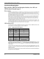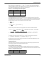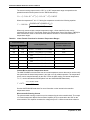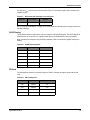
1
Stellaris® LM4F232 Evaluation Kit User’s Manual The OLED display has special reset timing requirements requiring a dedicated control line from the microcontroller. Power Supplies and Jumper The EK-LM4F232 can be powered from one of two power sources: Stellaris® ICDI USB cable (default) USB OTG cable A moveable jumper shunt on the POWER SELECT headers is used to select one of the two power sources. Only one source should be selected at a time. See “USB Host/Device/OTG” on page 10 for the recommended jumper positions for the specific USB modes. The evaluation board is designed to provide power to a limited amount of external circuitry. Table 2-10 shows the board’s power requirements and Table 2-11 shows the board’s breakout requirements. Table 2-10. Power Requirements Board Supply ICDI USB Cable USB OTG Cable Min Typical Max Unit 4.75 5.0 5.25 V Table 2-11. Breakout Requirements Breakout Condition Max Unit +3.3 V — 260 mA +3.3 V @ 260 mA, OLED on 350 mA +3.3 V @ 260 mA, OLED off 380 mA +5.0 Va,b a. This represents the +5.0 V breakout and the +VBUS breakout. Total current = I5V + IVBUS. b. +5.0 V is switched by the load switch (U7); however, +VBUS is always connected. Debug and Virtual COM Port (Schematic Page 4) Stellaris® In-Circuit Debug Interface (ICDI) and Virtual COM Port The EK-LM4F232 evaluation board comes with an on-board Stellaris® In-Circuit Debug Interface (ICDI). The Stellaris® ICDI allows for the programming and debug of the LM4F232H5QD using LM Flash Programmer and/or any of the supported tool chains. Both JTAG and Serial Wire Debug (SWD) are supported. NOTE: Although other Stellaris kits support debug out, the EK-LM4F232 evaluation board does not support this. You can use another Stellaris evaluation kit for debug out. An external debugger can be connected to the evaluation board through a 2 x 5 fine pitch (0.05”) ARM JTAG header. When connecting an external debugger, pin 3 of the JTAG header must be tied 18 September 14, 2012