1
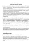
Installation & Quick Start Guide WL510 Wireless Adaptor/Antenna IMPORTANT INFORMATION ABOUT YOUR WL510 IP Address = 192.168.10.20 Password = wl510 QUICK START WL510-03- VR3.00 DIGITAL YACHT WL510 Quick Start Guide 1. Introduction Congratulations on the purchase of your WL510 Wireless Adaptor/Antenna. This unit is designed for permanent installation on board a sail or motor boat. The WL510 comprises the following parts; 2.4GHZ external antenna Base mount for antenna 10M LMR400 coax cable assembly WL510 Modem unit 1m RJ45 Cat5 network cable Manual Before operating this unit you should familiarise yourself with this Quick Start Guide and user manual for any equipment you wish to connect to it. 2. Before you start The WL510 is configured and controlled via its built-in web interface. In order to access this, you will need a PC with one RJ45 Ethernet (LAN) connection and a suitable modern web browser such as Internet Explorer, Chrome or Firefox. No drivers are required to be installed to make the WL510 work and any Windows, Mac OSX or LINUX powered PC can work with the WL510. Do not plug in the WL510 to the Ethernet port of your computer whilst the WL510 is powered up and always ensure that the WL510 is connected to the Antenna before powering up the WL510. 3. Mounting the WL510 Antenna The WL510 should be mounted in line of sight with the wireless router that you wish to connect to. Unlike VHF antennas, height is not critical and popular antenna locations include; cockpit guard rail, radar arch or wheel house roof. The WL510 antenna requires a 1.25” BSP thread mount which is larger than the popular 1” x 14TPI thread mount used by many VHF antennas. The WL510 is supplied with an antenna mount that is suitable for mounting to a flat horizontal surface (see Fig 1 below). However, if you wish to mount the WL510 antenna in a different manner, a variety of different brackets are available for this type of threaded mount but do not confuse it with the smaller 1” x 14TPI types. Please consult your local marine electronics dealer or chandlery for more information. Use of this system may be prohibited in certain localities and territories. Please check with Digital Yacht prior to operation. It is intended for offshore use only. The WL510 is a high power Wi-Fi access system with an ERP of 1W Installation The maximum distance from the antenna to the below deck modem unit is 10m as per the supplied cable. This is a specialist coax cable assembly and it should not be cut or lengthened. Mount the deck base using the supplied fasteners. Drill a clearance hole for the cable and connector through the deck. Screw the N type connector to antenna and mount the antenna onto base. Figure 1 Power Requirements The unit is only designed to work on vessels with a 12V DC system (10-18V DC Input voltage). It is supplied with an inline 3.15A fuse which should be connected if there is no suitable circuit breaker or fuse protected circuit for the WL510 to be connected to. The WL510 has a two core power cable with a Red (+12v) and Black (-0v) wire. Be very careful to ensure that the correct supply voltage polarity is connected to the WL510, as reverse polarity will damage the unit. DIGITAL YACHT WL510 Quick Start Guide 3. Connecting the WL510 to a single PC The WL510 can be connected directly to a single PC or via a Wireless Router so that it can be shared by multiple PCs and other wireless devices. If you wish to connect it to a Wireless Router please skip to section 4. The WL510 acts as a DHCP server on its LAN connection and will allocate an IP address to any PC connected to it, so it is important that your PC is set to “Obtain an IP address automatically” in the LAN Network Connection properties (as shown in Fig 1 to Fig 3) Fig 1 Fig 2 Fig 3 This is the default network settings for PCs, so once you have confirmed these settings or reset them, ensure the WL510 is turned off and then connect your PC’s ethernet RJ45 LAN socket to the WL510 LAN socket using the conventional 1m network cable (not cross over) supplied. This cable can be replaced with any length of normal RJ45 Cat5 network cable up to 60m in length. Confirm that you have connected the antenna to the WL510 and then apply power to the WL510. Over the next 10-20 seconds as the WL510 powers up, you should see some network activity and your PC will receive an IP address from the WL510 in the range 192.168.10.100 to 192.168.10.200. Your WL510 is now ready to connect to a Hotspot and provide long range internet connectivity to your PC. Proceed to Section 6 for details of how to scan for available networks (hotspots) and connect to them. 4. Connecting the WL510 to iNavConnect or iNavHub The WL510 really comes in to its own when you connect it to a Router (wireless or wired) and share its long range wireless connection with multiple PCs and mobile devices. The easiest solution is to use one of Digital Yacht’s own wireless routers; 1) iNavConnect – entry level wireless router 2) iNavHub – wireless router with integral NMEA to Wi-Fi converter Both units are powered directly from the boat’s 12v/24v DC supply and are housed in a rugged, IP54 rated enclosure that can be screwed to a bulkhead. These units work particularly well with the “Captive Portal” type Wi-Fi hotspots found in many marinas and are fully supported by Digital Yacht. It is important that the WL510 and iNavConnect/iNavHub are wired to the same switch/circuit breaker, so that the two units power up together and negotiate correctly to ensure that the WL510 provides IP addresses to the network. DIGITAL YACHT WL510 Quick Start Guide Connection to iNavConnect/iNavHub should be made with both units turned off. Use a normal RJ45 Cat 5 network cable (as supplied with both units) and the WL510 should be wired to the “Network/LAN” socket as shown in Fig 4 on the next page. Do NOT wire the WL510 to the “Internet/WAN” socket. Figure 4 Once the WL510 and iNavConnect/iNavHub are connected together, turn on the common switch/circuit breaker and you should see a steady red light on the WL510 and a flashing green light on LAN LED of the iNavConnect/iNavHub. Your WL510 is now ready to connect to a Hotspot and provide long range internet connectivity to your router. Proceed to Section 6 for details of how to scan for available networks (hotspots) and connect to them. 5. Connecting the WL510 to a 3rd Party Router If you already have a router that you wish to use or you want to use another make of router, the WL510 can be connected to any cable modem type router (rather than a phone line ADSL type). There are plenty of units available from manufacturers like Netgear, Belkin, Linksys, TP-Link, Cisco, etc. and although Digital Yacht have not exhaustively tested all of them, every unit that we have so far tested, worked fine with the WL510. Unfortunately Digital Yacht cannot provide support for installations that are using 3 routers, such as those previously listed. rd party commercial off the shelf Connection should be made with both the router and WL510 turned off and simply involves connecting the Ethernet RJ45 WAN (INTERNET) socket of the router to the WL510 LAN socket using the conventional 1m network cable (not cross over) supplied. It is important that the WL510 is connected to the router’s WAN socket and not one of the router’s LAN sockets. Confirm that you have connected the antenna to the WL510 and then apply power to the WL510, wait a couple of seconds and then apply power to the router. Over the next 10-20 seconds as the two devices power up, you should see some network activity and your router will receive an IP address from the WL510 in the range 192.168.10.100 to 192.168.10.200. Your WL510 is now ready to connect to a Hotspot and provide long range internet connectivity to your router. Proceed to Section 6 for details of how to scan for available networks (hotspots) and connect to them. DIGITAL YACHT WL510 Quick Start Guide 6. Using the WL510 to connect to a Hotspot The WL510 always has an IP address of 192.168.10.20. Whether you are connecting just one PC to the WL510 or multiple PCs via a router, to talk to the WL510, you must enter the IP address 192.168.10.20 in to the address bar of a browser on the PC or mobile device connected to the WL510 or router. You should then see the WL510 login page as shown in Fig 4. The first time that you log in, you will be asked to enter the country in which you are operating the WL510, language that you want the web interface to be displayed in and asked to confirm the terms and conditions. The password is “wl510” by default. All subsequent logins will just display the password box. Figure 4 Once logged in to the WL510, you will see the “STATUS” screen – see Fig 5. Normally this screen would display the connection status but as this is the first time you have logged in, there is no wireless connection to a network established. Click on the “WIRELESS” tab and you will be taken to the screen shown in screen, there are three key settings that need to be configured…. 1) Country Code – you have already set the country when you first logged in, but if you sail to a different country, then you must select the new country you are in from the drop down box. This sets the wireless channels to be used and the maximum legal power output for that country. 2) “Auto Adjust to EIRP Limit” – this tick box automatically regulates the maximum power that the WL510 transmits to keep it within the legal limits of the country you have selected. If you are off shore and want the maximum possible range, un-tick this box and manually adjust the “Output Power”. 3) Figure 5 – This slider is used to manually adjust the power output of the WL510 Output Power Once the above settings are configured click the “Change” button and then click the “Apply” button that will appear at the top of the page. To scan for available networks (hotspots), click on the “SCAN” button. A pop-up window will appear - see Fig 7. Figure 6 DIGITAL YACHT WL510 Quick Start Guide Every wireless network that the WL510 could detect is listed and this can often be quite a long list. It is sometimes useful to sort the list by signal strength or by encryption e.g. to see which networks are Open (free). To sort the list, click on the relevant column heading. The list will then be resorted by the category you have selected. From the list of available networks, select the one that you wish to connect to by clicking the tick box to the left of the networks “MAC Address”. Then click on the “Select” button. If the network is protected with a WEP/WPA/WPA2 password, you will be taken back to the “WIRELESS” screen and you will need to type in the password as shown in Fig 8. Figure 7 To make sure that you have typed the password correctly, you can click the Show tick box to display the password instead of hidden ******* characters. Once you have entered the correct password (if necessary), click the “Change” button followed by the “Apply” button that will appear at the top of the page. It usually takes up to 10 seconds for the connection to be established and when successful, a coloured signal strength meter will appear in the top right hand panel of the “STATUS” screen – se Fig 9. If the coloured signal strength meter starts a cycle of appearing and then disappearing, this means that the password you have entered is incorrect. Try correcting the password and then click the “Change” followed by the “Apply” buttons again. Figure 8 If the signal strength meter is stable and is indicating a value between -10db and -84db, then you should now be connected to the hotspot. Any values less than -84db and the connection may start to drop out. If you are struggling with low signal strength, you can try un-ticking the “Auto Adjust to EIRP Limit” box and sliding the Output Power slider to the right to increase the transmit power of the WL510. If this still fails to improve the signal strength of the connection then you may need to move closer to the Hotspot or re-position the vessel so that the WL510 antenna has a clearer line of sight to the Hotspot. If you click on the “STATUS” tab, you will display more information about the connection status including speed, quality and distance. At the bottom of the “STATUS” page you will see the Monitor screen which by default shows a series of data performance graphs. Above the graphs you will see a series of blue links to other monitor pages that provide a large amount of information that is useful for diagnostic purposes. Simply click on the relevant link to display this information. Figure 9 DIGITAL YACHT WL510 Quick Start Guide Assuming that; a) The hotspot you connected to has an Internet connection b) You have paid any necessary connection fees c) Entered any access codes Then you’re PC and any devices connected to the Router should now be able to connect to the internet. You can now log out from the WL510 web connection or simply navigate to another webpage on the internet. Although the WL510 does have many other settings, in reality, these are very rarely needed. IT IS STRONGLY RECOMMENDED that you do not change any of the settings in the “WIRELESS” of “NETWORK” pages. Only experienced network technicians should attempt changing any of these advanced menu settings. If you have problems with any of the advanced WL510 settings, it is recommended that you click the “Reset to Defaults” button on the “SYSTEM” screen.