1
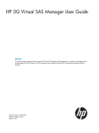
Installation & Quick Start Guide WL450 Wireless Antenna IMPORTANT INFORMATION ABOUT YOUR WL450 IP Address = 192.168.10.20 Password = wl450 QUICK START WL450-01- VR1.00 DIGITAL YACHT WL450 Quick Start Guide 1. Introduction Congratulations on the purchase of your WL450 Wireless Antenna. This unit is designed for permanent installation on board a sail or motor boat. The WL450 comprises the following parts; WL450 2.4GHZ Wireless antenna 10M Cat5e shielded network cable WL450 Power Over Ethernet (PoE) injector unit Manual Software and Driver CD-Rom Before operating this unit you should familiarise yourself with this Quick Start Guide and user manual for any equipment you wish to connect to it. 2. Before you start The WL450 is configured and controlled via its built-in web interface. In order to access this, you will need a PC with one RJ45 Ethernet (LAN) connection and a suitable modern web browser such as Internet Explorer, Chrome or Firefox. No drivers are required to be installed to make the WL450 work and any Windows, Mac OSX or LINUX powered PC can work with the WL450. IMPORTANT – The WL450 must be connected to the PoE socket on the Power Over Ethernet injector and the PC/Router/Switch connected to the LAN socket of the Power Over Ethernet injector. If these two connections are mistakenly swapped, then 12v DC will be applied to your PC/Router/Switch connection which could cause permanent damage to this equipment. 3. Mounting the WL450 Antenna The WL450 will have best performance when it has a clear “line of sight” with the wireless hotspot that you are trying to connect to. Most wireless hotspot antennas are mounted on buildings or on poles that are between 5-10m high. The WL450 antenna is omni-directional and has quite a narrow beam width of about 18 degrees. Height is not as critical as with a VHF antenna, as the TX/RX distances are much smaller and if mounted too high, you can actually “overshoot” the hotspot you are trying to connect to (see Fig.1). Choosing a mounting location is a compromise between getting enough height to get a clear line of sight (and reduce sea surface reflection effects) whilst not going so high that you overshoot the hotspot if moored too close. Popular antenna locations include; cockpit guard rail, radar arch or wheel house roof, although if you want maximum range the top of the mast is still the best location. Figure 1 The WL450 antenna base has the same standard 1” x 14TPI thread that is popular on VHF/GPS antennas. A variety of different mounts, brackets and clamps are readily available for this type of threaded mount. We recommend the use of a metal rather than plastic mount for the WL450. Please consult your local marine electronics dealer or chandlery for more information. The default settings of the WL450 ensure that the Wi-Fi transmissions are within the legal limits of the country that you have selected as your current location. If you do not select the correct country or you change the power settings from the defaults, you may be operating the equipment outside of the legal limits of certain localities and territories. Please check with Digital Yacht prior to operation. If in doubt only use the WL450 when offshore away from other Wi-Fi users. The WL450 is a high power Wi-Fi access system with an ERP of 1W WL450 Quick Start Guide DIGITAL YACHT Installation The WL450 is supplied with 10m of cable as standard (a 20m option is available). This cable carries both the data and power to the antenna so, in long cable runs, voltage drop can become an issue and we do not recommend extending this cable beyond 20m. If you do replace the supplied cable, only use Cat5e shielded cable that has all eight wires – some early network cables only fitted four wires. The base of the WL450 has a slot cut in it to allow the network cable to side exit the antenna. Some mounts have a hollow center allowing the cable a straight exit through the mount (see Fig.2) but in some cases a side exit is necessary or desirable (see Fig.3). Care must be taken to ensure the network cable is not twisted or stressed whilst attaching the WL450 to the mount. It is recommended that prior to fixing the mount in place that the mount is screwed on to the WL450, rather than the WL450 screwed on to the mount. This allows the cable to be kept in one position whilst the mount is fitted and avoids unwanted twisting of the cable. Figure 3 Figure 2 Once the WL450 is mounted in its final position, route the network cable through the deck to where the PoE Injector unit will be mounted. The PoE Injector must be mounted inside the boat in a dry location. Secure the PoE Injector using two suitable fixings (not supplied) to a vertical bulkhead with the connections facing downwards. The PoE Injector requires a fused 12v DC supply (1 Amp Fuse) and has a right angled DC jack plug (center positive) which has two wires for connecting to the boat’s 12v supply. WL450 Power Cable Fused 12v DC Supply Black Wire with White Stripe + 12 v (Positive) Plain Black Wire - 0v (Negative) Prior to plugging the DC jack plug in to the PoE Injector, we recommend using a multi-meter to take a DC voltage measurement between the Inner and Outer terminals of the connector to make sure that the polarity is correct. The inner (center) connector should be positive. This is very important as incorrect polarity can cause damage to the WL450. On boat’s with a 24v supply, a suitable 24v to 12v regulator must be used, as the WL450 is 12v only and connecting it directly to 24v could cause permanent damage to the WL450. The PoE Injector (see Fig.4) supplies 12v to the WL450 through the network connector marked POE. Under no circumstances should any other device be connected to this PoE connection as the 12v DC supply could cause damage to non-PoE devices such as PCs, routers, etc. WL450 Quick Start Guide DIGITAL YACHT Figure 4 With the power to the PoE Injector turned off, connect the WL450 network cable to the POE socket (black cable shown in Fig.4). The LAN connector of the PoE Injector should be connected to; 1) The Network socket of a PC/Mac in a simple, single computer installation 2) The Internet (WAN) socket of a Digital Yacht iNavConnect or iNavHub Wireless Router (see Fig.5) rd 3) The WAN socket of a suitable 3 Party Router 4) A spare LAN network socket on a suitable network switch Figure 5 In order for the WL450 to correctly connect to some public hotspots that use the “Captive Portal” technique (very popular with marinas for allowing different users to connect via a web based login page), it is necessary to set a secondary DNS setting in the router so that the re-direct to the marinas “Welcome” login page is properly triggered. If you are using our iNavConnect or iNavHub wireless routers, please go to the Appendix of this manual for details of how to configure this secondary DNS setting. rd If you are using a 3 Party router, you will need to consult the router’s user manual and find out how to setup a secondary DNS address – which should be set to 192.168.10.20 (IP address of the WL450). DIGITAL YACHT WL450 Quick Start Guide 3. Connecting the WL450 to a single PC The WL450 can be connected directly to a single PC or via a Wireless Router so that it can be shared by multiple PCs and other wireless devices. If you wish to connect it to a Wireless Router please skip to section 4. The WL450 acts as a DHCP server on its LAN connection and will allocate an IP address to any PC connected to it, so it is important that your PC is set to “Obtain an IP address automatically” in the LAN Network Connection properties (as shown in Fig 6 to Fig 8) Fig 6 Fig 7 Fig 8 This is the default network settings for PCs, so once you have confirmed these settings or reset them, ensure the WL450 is turned off and then connect your PC’s ethernet RJ45 LAN socket to the PoE Injector’s LAN socket using a conventional network cable (not cross over). Any length of network cable can be used up to 60m (maximum). Confirm that you have connected the antenna to the WL450 and then apply power to the WL450. Over the next 10-20 seconds as the WL450 powers up, you should see some network activity and your PC will receive an IP address from the WL450 in the range 192.168.10.100 to 192.168.10.200. Your WL450 is now ready to connect to a Hotspot and provide long range internet connectivity to your PC. Proceed to Section 6 for details of how to scan for available networks (hotspots) and connect to them. 4. Connecting the WL450 to iNavConnect or iNavHub The WL450 really comes in to its own when you connect it to a Router (wireless or wired) and share its long range wireless connection with multiple PCs and mobile devices. The easiest solution is to use one of Digital Yacht’s own wireless routers; 1) iNavConnect – entry level wireless router 2) iNavHub – wireless router with integral NMEA to Wi-Fi converter Both units are powered directly from the boat’s 12v/24v DC supply and are housed in a rugged, IP54 rated enclosure that can be screwed to a bulkhead. These units work particularly well with the “Captive Portal” type Wi-Fi hotspots found in many marinas and are fully supported by Digital Yacht. We normally recommend that the WL450 and iNavConnect/iNavHub are wired to the same switch/circuit breaker, so that the two units power up together and negotiate correctly at power up. If this is not possible and the units have to be on separate circuit breakers, you should power up the WL450, wait a couple of seconds and then power up the rd iNavConnect/iNavHub. This is also true when using the WL450 with 3 Party Routers, always power up the WL450 and then the router. DIGITAL YACHT WL450 Quick Start Guide Connection to iNavConnect/iNavHub should be made with both units turned off. Use a normal RJ45 Cat 5 network cable (as supplied with both units) to connect the WL450 PoE Injector’s LAN socket to the iNavConnect/iNavHub’s “Internet/WAN” socket as shown previously in Fig 5 on the next page. Once the WL450 and iNavConnect/iNavHub are connected together, turn on the common switch/circuit breaker and you should see a steady green light on the WL450’s PoE Injector and after approximately 10secs, the green WAN LED of the iNavConnect/iNavHub should start to flash as it talks to the WL450. Your WL450 is now ready to connect to a Hotspot and provide long range internet connectivity to your router. Proceed to Section 6 for details of how to scan for available networks (hotspots) and connect to them. 5. Connecting the WL450 to a 3rd Party Router If you already have a router that you wish to use or you want to use another make of router, the WL450 can be connected to any cable modem type router (rather than a phone line ADSL type). There are plenty of units available from manufacturers like Netgear, Belkin, Linksys, TP-Link, Cisco, etc. and although Digital Yacht have not exhaustively tested all of them, every unit that we have so far tested, worked fine with the WL450. rd Unfortunately Digital Yacht cannot provide support for installations that are using 3 routers, such as those previously listed. party commercial off the shelf Connection should be made with both the router and WL450 turned off and simply involves connecting the Ethernet RJ45 WAN (INTERNET) socket of the router to the WL450 LAN socket using the conventional 1m network cable (not cross over) supplied. It is important that the WL450 is connected to the router’s WAN socket and not one of the router’s LAN sockets. Confirm that you have connected the antenna to the WL450 and then apply power to the WL450, wait a couple of seconds and then apply power to the router. Over the next 10-20 seconds as the two devices power up, you should see some network activity and your router will receive an IP address from the WL450 in the range 192.168.10.100 to 192.168.10.200. Your WL450 is now ready to connect to a Hotspot and provide long range internet connectivity to your router. Proceed to Section 6 for details of how to scan for available networks (hotspots) and connect to them. DIGITAL YACHT WL450 Quick Start Guide 6. Using the WL450 to connect to a Hotspot The WL450 always has an IP address of 192.168.10.20. Whether you are connecting just one PC to the WL450 or multiple PCs via a router, to talk to the WL450, you must enter the IP address 192.168.10.20 in to the address bar of a browser on the PC or mobile device connected to the WL450 or router. You should then see the WL450 login page as shown in Fig.9. The first time that you log in, you will be asked to enter the country in which you are operating the WL450, language that you want the web interface to be displayed in and asked to confirm the terms and conditions. The password is “wl450” by default. All subsequent logins will just display the password box. Once logged in to the WL450, you will see the “STATUS” screen – see Fig.10. Normally this screen would display the connection status but as this is the first time you have logged in, there is no wireless connection to a network established. Figure 4 Figure 9 Click on the “WIRELESS” tab and you will be taken to the screen shown in Fig.11, there are three key settings that need to be configured. These settings should be used with care, as they affect the output power of the WL450 and may make it operate outside of the local legal limits for WiFi signal transmission. 1) Country Code – you have already set the country when you first logged in, but if you sail to a different country, then you must select the new country you are in from the drop down box. This sets the wireless channels to be used and the maximum legal power output for that country. 2) “Auto Adjust to EIRP Limit” – this tick box automatically regulates the maximum power that the WL450 transmits to keep it within the legal limits of the country you have selected. Only untick this option if you are off shore. 3) Figure 10 Output Power – This slider is used to adjust the power output of the WL450 and can only be adjusted if the “Auto Adjust to EIRP Limit” is unticked. Only make adjustments to this setting if you are off shore. Once the above settings are configured and you are sure that you are operating the WL450 within the legal limits of the country you are in, click the “Change” button and then click the “Apply” button that will appear at the top of the page. Figure 11 DIGITAL YACHT WL450 Quick Start Guide To scan for available networks (hotspots), click on the “SCAN” button. A pop-up window will appear - see Fig.12. Every wireless network that the WL450 could detect is listed and this can often be quite a long list. It is sometimes useful to sort the list by signal strength or by encryption e.g. to see which networks are Open (free). To sort the list, click on the relevant column heading. The list will then be resorted by the category you have selected. It is important to note that the signal strength values are shown in negative dBs. Therefore the smaller the number the better the signal strength i.e. -54dB is a stronger more reliable signal than -75dB Figure 12 From the list of available networks, select the one that you wish to connect to by clicking the tick box to the left of the networks “MAC Address”. Then click on the “Select” button. If the network is protected with a WEP/WPA/WPA2 password, you will be taken back to the “WIRELESS” screen and you will need to type in the password as shown in Fig.13. To make sure that you have typed the password correctly, you can click the Show tick box to display the password instead of hidden ******* characters. Once you have entered the correct password (if necessary), click the “Change” button followed by the “Apply” button that will appear at the top of the page. Older WEP passwords can be either HEX (0-9 and A-F characters) or ASCII (0-9, A-Z and some special characters). Also they can vary in length which can create problems when trying to enter the WEP passkey. If you have problems connecting to a WEP encoded access point please contact Digital Yacht for guidance. It usually takes up to 10 seconds for the connection to be established and when successful, a coloured signal strength meter will appear in the top right hand panel of the “STATUS” screen – se Fig.14. If the coloured signal strength meter starts a cycle of appearing and then disappearing, this means that the password you have entered is incorrect. Try correcting the password and then click the “Change” followed by the “Apply” buttons again. If the signal strength meter is stable and is indicating a value between -10db and -84db, then you should now be connected to the hotspot. Any values less than -84db and the connection may start to drop out. Figure 13 If you click on the “STATUS” tab, you will display more information about the connection status including speed, quality and distance. At the bottom of the “STATUS” page you will see the Monitor screen which by default shows a series of data performance graphs. Above the graphs you will see a series of blue links to other monitor pages that provide a large amount of information that is useful for diagnostic purposes. Simply click on the relevant link to display this information. The DHCP Client tab is particularly useful as it displays the network settings that the WL510 has been given by the Wireless Network you have connected to. Figure 14 DIGITAL YACHT WL450 Quick Start Guide The only known reason for a connection to a marina hot spot to not work, is if the IP address that the WL510 has been given by the wireless network is in the same range as the WL510 network address i.e. 192.168.10.xxx. If you find that the WL510 has been given an IP address in this range, then it may not be possible to connect to this particular hot spot without changing the WL510’s default IP address range. In this situation please contact Digital Yacht for advice on how to work around this problem. Another useful piece of information that is displayed in the DHCP Client tab is the “Lease Time” which is the amount of time that the network IP settings that the wireless network has given the WL510 will be valid for. If the Lease has expired then it will be necessary to renew the lease by clicking the “Renew” button. This is normally done automatically but in some case the lease can expire and it is necessary to renew it manually. Assuming that; a) The hotspot you connected to has an Internet connection b) You have paid any necessary connection fees c) You have entered the correct password (pass key) if the wireless network is encrypted (WEP/WPA/WPA2) d) You have registered/logged on to the Marina’s Welcome page with the correct access codes, if it is an Open network Then you’re PC and any devices connected to the Router should now be able to connect to the internet. You can now log out from the WL450 web connection or simply navigate to another webpage on the internet. Although the WL450 does have many other settings, in reality, these are very rarely needed. IT IS STRONGLY RECOMMENDED that you do not change any of the settings in the “WIRELESS” of “NETWORK” pages. Only experienced network technicians should attempt changing any of these advanced menu settings. If you have problems with any of the advanced WL450 settings, it is recommended that you click the “Reset to Defaults” button on the “SYSTEM” screen. DIGITAL YACHT WL450 Quick Start Guide APPENDIX: Entering a Secondary DNS Setting on iNavConnect/iNavHub We have found that many of the marinas use a method of connection called "Captive Portal" that makes the wireless network they create appear as an "Open" unprotected network, that you can connect to without a wireless password. Then when you try to open your browser and to go to a website, you are re-directed to the marina's "Welcome Page" where you are asked to register or enter a specific password or code that you have to get from the marina (usually for a small fee). In order for this re-direction to occur, it is important that the DNS settings that your PC or Mobile Device get from the iNavConnect/iNavHub, correctly point to the WL450. To ensure this always happens, we recommend that the following setting are made on the iNavConnect/iNavHub 1) Connect your PC or Mobile Device wirelessly to the iNavConnect/iNavHub 2) Open your browser and type the following IP address depending upon which unit you have; - iNavConnect = 10.0.0.1 - iNavHub = 192.168.1.1 3) At the login page, type the following password for the unit you have; - iNavConnect password = "inavconnect" - iNavHub password = "inavhub" 4) You will now see the main status page of the iNavConnect/iNavHub 5) Click on the “Network” tab and then click on the “Edit” button on the LAN interface (top line) DIGITAL YACHT WL450 Quick Start Guide 6) Now scroll down this page and in the lower "DHCP Server" section click on the "Advanced Settings" tab 7) In the very last "DHCP-Options" box type the following text depending upon the unit you have, making sure that you get the commas and full stop characters correct and no spaces; - For iNavConnect enter "6,10.0.0.1,192.168.10.20" - For iNavHub enter "6,192.168.1.1,192.168.10.20" DIGITAL YACHT WL450 Quick Start Guide 8) Once you have checked that you have typed this correctly, click on the "Save & Apply" button and your change of setting will be stored. Power off the iNavConnect and then power it on again. 9) Everything should now be set correctly and to test simply connect to any Marina Hotspot that makes you login on their “Welcome” page or alternatively to any national wireless operator’s (i.e. BT Openzone) hotspot as most of these operate in the same way. Once connected to the hotspot, in your browser click on a bookmark or type a website address in the address bar and you should see the marina or wireless operator’s login page.