1
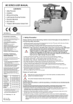
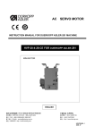
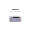
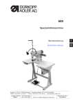
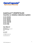
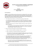
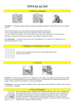
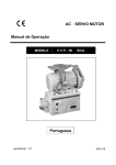
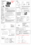
MA SERIES USER MANUAL
CONTENTS
1. Safety Precaution
2. Installation
3. Wiring and Grounding
4. Control Panel
5. Error Code List
HSVPMAU01-0
2008.03
EC Declaration of Conformity
We hereby declare that the following products:
1. Safety Precaution :
AC servo motor--MA、MB、MD、ME、MH、MF series
are in conformity with the provision of the EC
directives as following :
Please read this manual with sewing machine manual thoroughly and pay attention for the
following safety precaution.
-EC Low Voltage Directive (73/23/EEC)
-EC Electromagnetic Compatibility Directive
(89/336/EEC)
-EC Machinery Directive (98/37/EC)
Applied harmonized standards :
EN 60204-31 : Electrical equipment of industrial
machines. Particular requirements for sewing
machines, sewing units and sewing system.
EN 292-1 : Safety of machines.
EN 292-2 : Safety of machines, technical
guidelines and specifications.
EN 61000-6-2 : EMS for industrial environment.
EN 61000-6-3 : EMI for residential environment.
Declaration of Conformity for
Concentration Limits for Certain
Hazardous Substances
We hereby declare that the following products:
AC servo motor--MA、MB、MD、ME、MH、MF series
are complies with the following directives and
requirements :
1. European Union RoHS Directive (2002/95/EC) and
the concentration limits for certain hazardous
substances (2005/618/EC)
2. People’s Republic of China Electronic Business
Standard : Requirements for concentration limits for
certain hazardous substances in electronic
information products (SJ/T 11363-2006)
Our product itself (motor, control box) or its packing
materials and accessories (box, screws package,
user manual, sticker, label, print…etc.) or the
suppliers of parts and raw materials are all in
conformity with the provision of the European Union
RoHS Directive and People’s Republic of China
Electronic Business Standard to conform the
following concentration limits for the six hazardous
substances :
Hazardous
Substance
Permissible Values
Lead (Pb)
Less than 240 ppm
Mercury
(Hg)
Cadmium
(Cd)
Hexavalent
chromium (Cr VI)
Polybrominated
Biphenyl (PBB)
Polybrominated
Diphenyl ether
(PBDE)
Less than 800 ppm
Less than
80 ppm
Less than 800 ppm
Less than 800 ppm
Less than 800 ppm
*The concentration of lead in the lead-free process
for PCB shall be less than 800 ppm.
*For packing materials shipped with our products
or parts, the hazardous substances shall be 80
ppm or less in sum of Pb+Hg+Cd+Cr VI.
H. S. Machinery. Co., Ltd.
Mr. C. H. Tai
Plant Manager
․Installation and operation must be done by the trained personnel, also turn off the power switch and remove the plug
from outlet and wait for 5 minutes before any installation.
․This product is designed for the specific sewing machines and must not be used for other purposes.
․Only use the power voltage as described on the name plate of the MA motor and control box in ±10 % ranges.
※Attention : If the control box is AC 220V system, please don’t connect to the AC 380V power
outlet, otherwise the error will occur and panel LED will blink continually. If that
happened, please turn off the power switch immediately and check the power
voltage. Continue supply the 380V power over 5 minutes might damage the
fuses (F1,F2) of EMI board and burst the electrolytic capacitors (C4,C5) of power
board and even might endanger the person safety.
․In order to prevent abnormal operation, keep the product away from the high frequency machines.
․Don’t operate in direct sun light、outdoors area and the room temperature is 45°C above or 5°C under.
․Don’t operate near the heater、dew area and the humidity is 30 % less or 95% more.
․Don’t operate in dusty、evaporate、combustible gas area, and stay away from corrosive material.
․Don’t apply heavy objects or excessive force on the power cord, also don’t bend or pull the power cord.
․Power cord must keep 3 cm or above distance away from the V-belt and the pulley.
․In order to prevent the static interference and current leakage, all grounding works must be done properly.
․After power on the machine for the first time, use low speed to operate and check the correct rotation direction.
․During machine operation, don’t touch any moving parts.
․All moving parts must have protective device to avoid the body contact and objects insertion.
․Maintenance and repair must be done by the properly trained technician, also all the spare parts for repair must be
approved or supplied by the manufacturer.
․Don’t use any objects or force to hit or ram the product.
Danger and caution signs
Risks that may cause personal injury or risk to the machine are marked with this
symbol in the instruction manual.
This symbol indicates electrical risks and warnings.
Limited Warranty
Warranty period of this product is 1 year from purchasing, or 18 months from our manufacturing date.
Warranty Detail
Any trouble found within warranty period under normal use condition in conformance with this manual, it will be
repaired free of charge. Repair will be chargeable in the following cases even if within warranty period :
1. Inappropriate use include: wrong connecting high voltage, wrong application, disassemble, repair, modification by
incompetent personnel, or operate the product without the precaution, or operate the products out of its
specification range. Insert odd objects or liquids into the product.
2. Damage by fire, Earth quake, lighting, wind, flood, salt corrosive, moisture, abnormal power voltage and any other
damage cause by the natural disaster or by the inappropriate environments.
3. Dropping after purchase, or damage in transportation by customer himself. (or by customer’s shipping agency)
Note : We put our best effort and mind in testing and manufacturing for assuring the quality and reliable of this product.
But it is possible this product can still be damaged due to external magnetic interference and electronic static or
noise or unstable power source more than expected; therefore the grounding system of operate area must be
well-connected to this product and it’s also recommended to install a failsafe device. (such as residual current
breaker).
2. Installation :
MA installation
c). Install the V-Belt on the motor and
machine pulley, then adjust the
belt to its appropriate tension.
b). Install the pedal with
speed control unit.
a). Install the motor and
control box under the
table
Hazardo us vo ltage
will cause i njury.
Tur n off main switch
and wai t 5 mi nutes
bef ore openin g this
cov er .
Hazardo us vo ltage
will cause i njury.
Tur n off main switch
and wai t 5 mi nutes
bef ore openin g this
cov er .
Hoch spannung
Un volt age n on adapte Un voltaje inadecuado
pu ede p rovocar las
prov oque des
ver letzungsgefahrl
her idas.
Bit te schalten sie den blessur es.
hau ptschalter aus un d Eteind rel inter rupteur Apagar el interr uptor
war ten sie 5 minut en, et attendre 5 minutes pr incipal y esperar 5
bev or sie diese
avan td ouvr ir le capot. m inutos antes de
abr ir esta cubierta.
abd eckung offn en.
Pedal
Hazardo us vo ltage
will cause i njury.
Tur n off main switch
and wai t 5 mi nutes
bef ore openin g this
cov er .
MA series
Un volt age n on adapte Un voltaje inadecuado
Hoch spannung
pu ede p rovocar las
ver letzungsgefahrl
prov oque des
her idas.
Bit te schalten sie den blessur es.
hau ptschalter aus un d Eteind rel inter rupteur Apagar el interr uptor
war ten sie 5 minut en, et attendre 5 minutes pr incipal y esperar 5
bev or sie diese
avan td ouvr ir le capot. m inutos antes de
abr ir esta cubierta.
abd eckung offn en.
Synchronizer installation
Caution :
For person safety, turn off the power switch and remove
the power plug from outlet before any adjustment.
Hand wheel
Hexagonal
screw
Synchronizer Adjustment ( Please open the top cover first )
Synchr
onizer
Needle up position : Rotate the machine pulley to reach mechanical needle up
position and turn the photo disc (A) until its red mark is
aligned with the red mark on the bearing cover plate.
Needle down position : Rotate the machine pulley to reach mechanical needle
down position and turn the photo disc (B) until its blue
mark is aligned with the red mark on the bearing cover
plate.
Note: Instruction above is the standard adjustment. If you feel the position wasn’t
accurate, please do the fine tuning by yourself.
Stopper
To control box
Setting screw
Mounting the Synchronizer onto the flange of
hand wheel and match the stop groove of the
synchronizer with the stopper of the machine
head then tighten and secure 2 hexagonal
screws of the synchronizer rotor, then connect
the synchronizer cable to the control box.
Note : Stopper type and location might be
varied, depend by the machine model.
Bearing cover plate
..
.
Photo disc (A)
Photo disc (B)
Speed control unit adjustment
Components of speed control unit : see figure
Caution :
For person safety, turn off the power
switch and remove the power plug
from outlet before any adjustment.
Term of adjustment
1
2
3
A:
B:
C:
D:
Spring for toeing forward force adjustment
Bolt for heeling backward force adjustment
Pedal arm
Pitman rod for pedal
decrease
increase
B
C
Adjustment result
Toeing forward
Spring A move to right = force increased
force adjustment
Spring A move to left = force decreased
Heeling backward
Bolt B turn
= force decreased
force adjustment
Bolt B turn
= force increased
Pedal stroke
Rod D secure at right = stroke is longer
adjustment
Rod D secure at left = stroke is shorter
D
decrease
A
increase
3. Wiring and Grounding :
Caution :
Single phase ( AC220V )
1. Green / Yellow wire is for grounding, and
all grounding works must be done
properly.
Brown wire
Blue wire
Green / Yellow
(ground wire)
To control box
Three phase ( AC380V )
R
S
T
Brown wire
Black wire
Blue wire
Green / Yellow
(ground wire)
To control box
When multiple 1Φ / 220 V motors are connected to a 3 Φ / 220 V power source, take caution for the load balance
of each R, S, T phase, see the following diagram :
R
S
T
PE
Grounding
system
Haz ard ou s vo ltage
will c au se inju ry.
Turn off ma in switch
an d wa it 5 minu tes
be fore o p enin g th is
co ve r.
H och sp an nu ng
U n v oltag e no n a dap te U n vo ltaje ina de cu ado
p ue de p ro vo car las
p rov o qu e de s
v erletz un gsg efa hrl
h erid as.
Bitte sc ha lt e n sie d en b less ures .
h au ptsc ha lt e ra us u nd Etein dre l in terrup teu r A pag ar el in te rrup tor
w arten s ie 5 min ute n, e t a tte nd re 5 m inu tes p rinc ip al y e spe rar 5
a va ntd o uv rir le cap ot. m inu to s an tes d e
b ev or sie d iese
a brir esta c ub ierta.
a bd eck u ng o ffn en.
How to connect a 1Φ / 220 V power from a 3 Φ / 380 V power source
Attention : Must have a neutral point layout
Caution : If the power source
does not have the neutral point,
then this 1Φ / 220 V servo
motor is not suitable for this
connection. Please ask supplier
to offer our 3Φ / 380 V servo
motor.
Neutral point
Grounding system
Motor
Motor
Motor
4. Control Panel :
2
2
3
Control panel key functions :
4
1
6
5
After power ON, the p,q,r,s 4 LEDs will
blink and run in a clockwise or counterclockwise
direction 2 times which indicate the motor rotate
direction, then 4 LED blink together 2 times and
stop which confirm the LEDs are in good
condition.
RESET to the factory setting :
n Sewing speed adjust knob
Knob turn counterclockwise : speed down.
Knob turn clockwise : speed up.
o Power ON LED
Power ON, LED ON.
Power OFF, LED OFF.
p Start back tacking
LED ON=function ON. / LED OFF=function OFF.
q End back tacking
LED ON=function ON. / LED OFF=function OFF.
r Slow start
Press the key, LED ON=function ON.
Press the key, LED OFF=function OFF.
s Needle stop (up/down) position when motor stop
Press the key, LED ON : Stop at UP.
Press the key, LED OFF : Stop at DOWN.
Clockwise direction
6
5. Error Code List :
ER0. 1
ER0. 4
ER0. 5
ER0. 7
ER0. 8
ER0. 9
ER0. 11
5
+
+ Power ON
Press & hold
After RESET, the
p,q,r,s 4
LEDs will blink
together 4 times
to indicate the
setting has
completed.
After counterclockwise or
clockwise direction changed,
confirm the correct running
direction of the p,q,r,s 4
LEDs.
+ Power ON
p q
Panel LED for error code :
1. When MA control box is malfunction or abnormal, the error message will be warned by the
blinking of p,q,r,s 4 LED on the control panel. (See the following list)
2. Repair and maintenance must be performed by the properly trained technician.
Error code
6
Change motor rotate direction :
Counterclockwise
direction
Panel LED
blinking
When control box need to recover
the factory default setting, see the
following for instruction :
Cause of the problem
1. Power module detected error.
2. Abnormal over current occurred.
s r
Condition and solution
Motor and machine will be shutting down.
Please check the power module.
Please check the power board over current protection circuit.
Motor and machine will be shutting down.
Please check the AC power source.
1. When power on, higher power voltage has *If control box is AC 220V system, don’t use the AC 380V power
been detected.
voltage, otherwise the panel LED will blink continually after 2
2. Connect to a wrong AC power source.
second of power ON. If continue supply the 380V power, the
3. Aluminum casing resistor for the brake
electrolytic capacitors (C4,C5) of power board will burst open
circuit is defective or power board F1 fuse
over a period of time and cause the fuses (F1,F2) of EMI board
burst.
open circuit.
Please check the power board.
Please check the aluminum casing resistor and power board F1 fuse.
1. When power on, lower power voltage has Motor and machine will be shutting down..
been detected.
Please check the AC power source
2. Connect to a wrong AC power source.
Please check the power board.
Motor and machine will be shutting down.
1. Bad connection to the motor connector.
Please check the motor or motor connectors’ connection.
2. Synchronizer (sensor) signal error.
3. Machine locked or object stuck in the motor Please check the synchronizer (sensor) and its signal.
Please check machine head to see if any objects stuck in the motor
pulley.
pulley, or machine does not rotate smoothly.
4. Sewing material is too thick.
Operation box to CPU interface has
communication error.
Motor and machine will be shutting down.
Please check the operation box.
Motor still can run, but all output signals and operation box’s pattern
sewing function will be invalid.
Please check machine’s solenoids or the resistance value is 2 Ω less.
Please check all the power transistors which related to solenoid
Motor and machine will be shutting down.
If parameter【121.ANU】is set ON, but motor Please check synchronizer’s up position signal.
Please check control box.
can not find the needle up position signal
Please check machine head to see if any objects stuck in the motor
when power on.
pulley, or machine does not rotate smoothly.
1. Machine solenoid shorted.
2. Main board’s power transistor circuit was
defected.
ER0. 12
Power on, no synchronizer signal was
detected or synchronizer is not connected.
Automatic starts the clutch mode.
Please check the synchronizer and its connection.
ER0.16
1. Safety switch is defected or bad
Motor stopped
connection.
Please check the safety switch.
2. Parameter【075. SFM】setting not match Please check parameter【075. SFM】setting, make sure it match
the machine head model.
machine head’s safety switch.
If you need the technical support, please contact your distributor or browse our website at http://www.hohsing.com