1
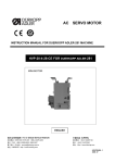
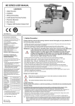
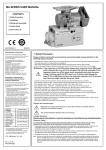
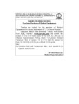
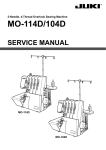
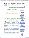
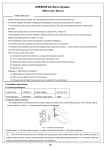
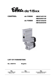
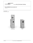
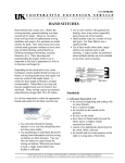
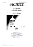
Operation Panel
Operation Instruction Manual
第 1 页 共 22 页
1. Operation Panel Overview
Operation panel (as shown in fig. 1-1), the front surface is divided into two parts:
LED Display Area and Push-button Area. And on upper right of operation panel, there is
a thumb wheel which is available to be turned C.W and C.C.W.
Fig. 1-1
The LED Display Area is on upper-center of the operation panel. The functional
parameter display is made up for 6 LEDs. There is a push-button on each side of display area;
they are the “Function Key”, “Cycle Key”. Under the display area, there are 12 push-buttons,
with LED on upper right or left to show whether the function is on or off.
Fig. 1-2
Detailed description of each push-button is shown in table-1.
Table 1: Push-button description of operation panel
No. Sign
1
2
Description
Function Key: Main function is to confirm operation and also can be used with
other buttons for key-combinations;
Cycle Key: Change parameter position when configuration;
Front-end Back tacking Key: Cycle selection among the single, double,
3
quadruple and none front-end back tacking. After selection, different
combinations of upper left and right LEDs will show the current status;
4
Rear-end Back tacking Key: Cycle selection among the single, double,
quadruple and none rear-end back tacking. After selection, different
第 2 页 共 22 页
combinations of upper left and right LEDs will show the current status;
Free-sewing Mode Key: After this mode is selected, LED on upper left will be
5
lighted;
Multi-section Sewing key: After this mode is selected, LED on upper left will be
6
lighted;
W-type Sewing Key: Select W-type sewing mode. After selection, the upper left
7
LED will be lighted;
Soft-start Key: Select soft-start mode. After selection, the upper left LED will be
8
lighted;
Foot Lifting Key: Automatic foot lifting setting. Select foot lifting and mid-foot
9
lifting functions. After selection, upper left and upper right LED combination
will show the current status;
Trimming Key: Select/not select auto trimming. After selection, the upper left
10
LED will be lighted;
Trigger Key: Select/not select trigger mode. After selection, the upper left LED
11
will be lighted;
Needle Stop Position Key: Select up/down needle position. After the up needle
12
position is selected, the upper left LED will be lighted;
Sewing Lamp Key: Select on/off the illumination lamp. After lamp on is
13
selected, the upper left LED will be lighted;
Stitch Compensation Key: Compensation function is on when you press the key,
the function will be off when you release it. After compensation function is
14
selected, the upper left LED will be lighted;
2. User Mode Definition
2.1 Operator Mode
This mode is the default mode of operation panel; operation panel will enter this mode
automatically after switched on. After entering this mode, the 6 decimal points of LED will
move in couples (display likes
), this means HMI is in idle condition.
When doing any operation, if you don’t press any button or turn thumb wheel for a long
time, HMI will switch to idle mode automatically and the previous operation will not be
executed!
第 3 页 共 22 页
2.1.1 Sewing Mode Set Up:
Free Sewing Mode: Press
press
, LED displays
, then if you
to confirm operation, LED display will recover to idle condition and upper
left LED of
will be lighted.
, LED displays
Multi-section Sewing Mode: Press
,
this is the operation interface of multi-section sewing. You can use the thumb wheel to
confirm N sewing sections according to your need, then press
parameters and quit the interface, or press
, to confirm
, LED displays
,
entering the interface of stitch number set-up for each section. In this interface, you can
to choose the section which should be changed, then use thumb wheel to
use
change stitch number, after operation is done, press
to confirm the parameters
and quit the interface, then LED display will recover to idle condition. So long as the
multi-section sewing mode is on, upper left LED of
W-type
Sewing
Mode:
displays
Press
,
enter
will be lighted.
W-type
sewing
function,
, this is W-type sewing interface. You can use
LED
to
switch over A, B, D section, and use thumb wheel to change stitch number of each
section. After confirmation, press
, then LED display will recover to idle condition,
and upper left LED of
will be lighted.
2.1.2 Front-end/Rear-end Back tacking Setting:
When
mode.
press
When press
double
or
, LED enters front-end or rear-end back tacking setup
, LED cycles among the single
, quadruple
front-end back tacking interfaces. When press
,
, and none
, LED cycles among the single,
to
double, quadruple and none rear-end back tacking (fig. omitted). You can press
switch section A, B or C, D, and use thumb wheel to change stitch number of each
section. After changing, press
to confirm operation, LED display will recover to idle
第 4 页 共 22 页
condition. The two LEDs on front-end or rear-end back tacking key will be lighted to
show corresponding conditions.
are both off, means none back tacking;
When 2 LEDs on
When upper left LED on
tacking;
is on, upper right is off, means single back
When upper left LED on
tacking;
is off, upper right is on, means double back
are both on, means quadruple back tacking.
When 2 LEDS on
Note: above instruction we provide pictures of front-end back tacking
2.1.3 Soft-start Set Up:
press
to select soft-start function, after selection, LED on upper left of
be lighted. Press again can quit soft-start condition; LED on upper left of
will
will be off.
2.1.4 Foot Lifting Set Up:
Use
to choose foot lifting mode, there are four different modes:
auto-foot-lifting;
, means auto-foot-lifting after trimming;
when stop during sewing;
, means no
, means auto-foot-lifting
, means auto-foot-lifting after trimming and stop during
sewing. Use
to cycle select among these four modes, after selection the LEDs will
also show in corresponding conditions.
2.1.5 Trimming Set Up:
Use
: to choose auto-trimming mode. When it’s auto-trimming, upper left LED of
will be lighted; when auto-trimming is off, upper left LED of
2.1.6 Trigger Set Up:
Use
will be off.
: to choose trigger mode. When it’s in trigger mode, upper left LED of
will be lighted; when trigger mode is off, upper left LED of
will be off.
2.1.7 Needle Position Position Set Up:
Use
to choose up/down needle position. When down position is selected, upper
left LED of
be off.
will be lighted; when up position is selected, upper left LED of
2.1.8 Sewing Lamp Set Up:
Use
to turn on/off sewing lamp. When turn on the lamp, upper left LED of
is on; when turn off the lamp, upper left LED of
2.1.9 Stitch Compensation Set Up:
will be off.
第 5 页 共 22 页
will
Use
to activate stitch compensation function, when you release the button, the
will be
function will be deactivated. When the function is selected, upper left LED of
lighted, otherwise the LED of
will be off.
2.2 Technician Mode
When HMI is in idle condition, press
interface, LED displays
first, then press
to enter technician
. Then use thumb wheel to change value
directly in the digit position with the flashing decimal point, you can use
to change
position of the flashing decimal point. After confirmation, press
. If you don’t press
any button or turn thumb wheel within the certain time, HMI will recover to idle condition
automatically.
2:Parameter List of Technician Mode
Para.
Para.
Para.
Default
Value
Type
max
min
Value
Range
0
200
Remark
100
Start sewing speed
~800
200
1
Max. speed of free sewing mode(Max. speed limitation
2500
~3000
of overall situation)
200
2
2500
Max. speed of fixed-length sewing
~3000
200
3
2500
Max. speed limitation of manual backstitch
~3000
Speed
0
Para.
100
4
200
Stitch compensation speed
~800
100
5
250
Trimming speed
~500
6
0
0 /1
Slow-start mode:0; slow-start only after trimming,1:after
trimming, sewing stop, both has slow-start
7
2
8
200
1 ~9
Slow-start stitch number
100
Slow-start speed
~800
第 6 页 共 22 页
Para.
Para.
Para.
Default
Value
Type
max
min
Value
Range
Remark
System acceleration sensitivity(for direct drive, the value
can be bigger; for belt drive, don’t use big value, which
9
20
1 ~20
will make more vibration and noise. This Para. Will not
affect motor torque)
System deceleration sensitivity (for direct drive, the value
can be bigger; for belt drive, don’t use big value, which
A
20
1 ~20
will make more vibration and noise. This Para. Will not
affect motor torque)
200~120
B
800
Medium speed value(RPM)
0
C
50
0
800
25~200
Low speed value(RPM)
200
Front-end back tacking speed
~2200
200
1
800
Rear-end back tacking speed
~2200
200
2
800
tacking
W-type sewing speed
~2200
Back
1
Para.
3
26
0 ~70
Front-end back tacking, No.1 stitch compensation profile
4
37
0 ~70
Front-end back tacking, No.2 stitch compensation profile
5
26
0 ~70
Rear-end back tacking, No.1 stitch compensation profile
6
37
0 ~70
Rear-end back tacking, No.2 stitch compensation profile
9
200
1~999
A
180
10~359
Auto back tacking section stop time CT(ms)
Stitch compensation reference angle(optimum actuation
angle of backstitch electromagnet)
Start back-tacking mode selection:
0;One shot sewing
Back
1;Pedal control and motor can stop at middle way.
tacking
2
0
0
0/1/2/3
2;One shot sewing but motor stops at needle up by CT
Mode
timer at end of each seam.
3;One shot sewing but motor stops at needle down by
第 7 页 共 22 页
Para.
Para.
Para.
Default
Value
Type
max
min
Value
Range
Remark
CT timer at end of each seam.
At the end of Start back-tacking mode selection.
0;At the end of Start back-tacking ,machine continues
sewing if pedal pressed or START signal on (standing
operation)
1
0
0/1/2
1;At the end of
Start Back-Tacking, machine stops and
must re-start by pedal command.
2;Making the trimming cycle once the Start
Back-Tacking finished. ( Mini Bar tacking )
Automatic sewing End mode selection
2
0
0/1
0;Start back-tacking
1;Active when motor stop,Invalid.
End back-taking mode selection.
0;One shot sewing
1;Invalid
3
0
0/1/2/3
2;One shot sewing but motor stops at needle up by CT
timer at end of each seam.
3;One shot sewing but motor stops at needle down by
CT timer at end of each seam.
Bar-tacking mode selection.
0;One shot sewing
1;Pedal control and motor can stop at middle way.
4
0
0/1/2/3
2;One shot sewing but motor stops at needle up by CT
timer at end of each seam.
3;One shot sewing but motor stops at needle down by
CT timer at end of each seam.
5
0
0 ~99
Setting stitches C of End
6
0
0 ~99
stitches plus on Start back-tacking
7
0
0 ~99
stitches plus on End back-tacking
8
0
0 ~3
frequence of middle fixed length back tacking
第 8 页 共 22 页
back-tacking
Para.
Para.
Para.
Default
Value
Type
max
min
Value
Range
9
0
0 ~99
Remark
needle number of middle backing tacking
Pedal speed-control profile mode:
0:Auto linear ramp(auto calculation according to max.
speed)
Speed
Pedal value
1:Two-stage ramp (can be set up freely, use Para. No.31
and No.32)
Speed
Pedal
0 /1 / 2 /
3
Para.
0
2
Pedal value
3
2:Power law curve(use No.33)
Speed
Pedal value
Pedal
3:S-type curve(first slow then quick, better operation in
low speed)
Speed
Pedal value
第 9 页 共 22 页
Para.
Para.
Para.
Default
Value
Type
max
min
Value
Range
Remark
Sub-para. Of two-stage speed control: mid-turning-point
speed RPM (two-stage ramp turning point speed), only
valid when para. No.30’s value is 1.
Pedal
200
3
1
3000
Para.
Speed
~4000
Mid-turning
Pedal
-point speed
Sub-para. Of two-stage speed control ramp:
Pedal analog value of mid-turning-point, valid when
Para. No.30 is set to 1, the para. Value should be in the
range from para. No.38 to para. No.39.
800
0 ~1024
2
Speed
Mid-turning-point
Analog Value
Pedal Value
Pedal
Para.
Sub-para. Of power speed control curve:
3
Valid when para. No.30 is 2.
1: Square(slow first, faster later, easy to control in low
speed);
Speed
3
2
1 /2
Pedal Value
2:Radication(fast first, slower later, response fast);
Speed
Pedal value
第 10 页 共 22 页
Para.
Para.
Para.
Default
Value
Type
max
min
Value
Range
4
150
0 ~1024
Remark
Trimming pedal-position set up, see fig. 2-1
(setting value should no bigger than Para. No.35)
Foot lifting pedal-position set up, see fig.2-1
5
300
0 ~1024
(Setting value should be in the range of para.No.34 and
para. No.36)
Pedal mid-homing position, see fig. 2-1.
6
460
0 ~1024
(Setting value should be in the range of para. No.35 and
para. No.37)
Pedal forward running position, see fig. 2-1.
7
480
0 ~1024
(Setting value should be in the range of para.No.36 and
para. No.38)
Pedal low speed running position (upper limitation), see
fig. 2-1.
8
680
0 ~1024
(Setting value should be in the range of para.No.37 and
para. No.39)
Pedal max. Analog value, see fig. 2-1.
9
960
0 ~1024
(Setting value should be no less than para.No.38)
A
0
0 ~800
Pedal foot lifting confirming time
After pedal back to homing position then trimming
selection start:
B
0
0/1
0:off
1:on
Foot lifting position, foot lifting function selection:
C
1
0/1
0: without
1:with
Trimming position, foot lifting function selection:
D
1
0/1
0: without
1:with
Auto upper needle stop position search after switch on:
0
1
0/1
0: function on 1: function off
第 11 页 共 22 页
Para.
Para.
Para.
Default
Value
Type
max
min
Value
Range
Remark
Auto back tacking function selection:
(for machines without this function, we suggest to
1
Customize
1
0/1
4
deactivated this function
Set up
0: function off 1:function on
Function mode selection when manually push back
tacking
2
0
0/1
0:Juki mode. During sewing or stop sewing both have
this action.
1:Brother mode. Only acts during sewing.
Special operation mode:
0: Operator selection
1: Simply sewing mode
0/1/
3
0
2: Motor initial angle measurement (not necessary to
2/3
remove the belt)
3: Ratio mode calculation (synchronize encoder is
necessary and belt can not be removed)
Motor torque increase function in low speed on & off:
4
0
0—31
0: Normal functions
1-31: low speed torque increase level
Needle stop mode:
0: Constant speed idle mode (in belt drive mode, stop
5
1
0/1
accuracy is not high)
1: Pull-back mode (PMX mode)
6
100
0 ~800
Instruction execution time of half stitch compensation
7
150
0 ~800
Instruction execution time of one stitch compensation
0/1/
Needle compensate:0.press time to
8
0
2
Count
5
control;1.half needle;2.one whole needle
9
0
Running-Delay time setting after foot lift
A
0
0~10
The larger the value the faster to up speed
0
1
1~
Stitch counting proportion set up
第 12 页 共 22 页
Para.
Para.
Para.
Default
Value
Type
max
min
Value
Range
Remark
Mode
100
1~
1
1
Stitch counting value set up
9999
Stitch counting mode selection:
0: no counting
1: Counting up according to stitch number, after reaching
set value then restart.
2: Counting down according to stitch number, after
reaching set value then restart.
3: Counting up according to stitch number, after reaching
2
0
0~4
set value, then motor should stop automatically,
recounting should be restart by S4 [152.INI] =CRS or the
button A on operation panel.
4: Counting down according to stitch number, after
reaching set value, motor should stop automatically,
recounting should be restart by S4 [152.INI] =CRS or the
button A on operation panel.
1~
3
1
Trimming counting proportion set up
100
1~
4
1
Trimming counting value set up
9999
Trimming counting mode selection:
0: no counting
1: Counting up according to stitch number, after reaching
set value then restart.
5
0
0~4
2: Counting down according to stitch number, after
reaching set value then restart.
3: Counting up according to stitch number, after reaching
set value, then motor should stop automatically,
recounting should be restart by S4 [152.INI] =CRS or the
第 13 页 共 22 页
Para.
Para.
Para.
Default
Value
Type
max
min
Value
Range
Remark
button A on operation panel.
4: Counting down according to stitch number, after
reaching set value, motor should stop automatically,
recounting should be restart by S4 [152.INI] =CRS or the
button A on operation panel.
0
0
0
Running time reset
Para. transmission method:
0: no action;
1
0
0/1/2
Operatio
n
1: Para. Download (from operation panel to controller);
6
2: Para. Upload (from controller to operation panel).
2
2000
1, 2, 88
3
0
1, 2
Recover to default para.
Save current para. As User custom para.(recoverable)
Note: operation para. Of (6X) will not be save.
图 2-1 踏板动作参数各位置示意图
2.3 Administrator Mode
When
displays
HMI in
idle
mode,
first
press
,
then
press
,
to
enter
administrator
use thumb wheel to change value with the flashing radix point, and
change flashing point position. After the value is confirmed, you can switch to next para. Or press
interface,
can be used to
to confirm modification. If
you don’t press any button or turn thumb wheel in a certain time, system will automatically switch to HMI idle condition.
Table 3: Para. List of Administrator mode
第 14 页 共 22 页
LED
Para.
Para. No.
Para. No.
Defaul
Type
max
min
t Value
Value Range
Remark
Motor running mode at
trimming sequence
0: For general Lock-Stitch
0
0
0/1
machines .
1:For general Cover stitch
machines with under trimmer
only.
Mech. Angle when trimming
1
0
0~359
finished
Trimming time sequence
selection:
0: [TS] set angle start
trimming, until upper needle
stop position is reached, then
time delay to [T2] set value.
Trimming Mode
0
1: [TS] set angle start
trimming, until [TE] set angle.
2: [TS] set angle start
trimming, time delay to [T2]
0/1/2/3/4
2
1
set value.
/5/6
3: After lower needle stop
position is reached, time delay
to [T1] set value then start
trimming, time delay to [T2]
set value.
4: After upper needle stop
position is reached, time delay
to [T1] set value then start
trimming, time delay to [T2]
set value, most applications
第 15 页 共 22 页
Para.
Para. No.
Para. No.
Defaul
Type
max
min
t Value
Value Range
Remark
are for interlock machines.
5: After lower needle stop
position is reached then start
trimming until to the upper
position. Time delay to T1 set
value then start T2 set
trimming time. (Most
applications are for flat sewing
machines, and set value for T1
and T2 are mostly 0)
6: [TS] set angle start
trimming until upper needle
stop position. Time delay to
T1 set value then start T2 set
trimming time.
Trimming start angle TS
3
10
5-359
(relate to lower needle stop
position angle)
Trimming finish angle TE
(relate to lower needle stop
4
300
10-359
position angle, the value
should be bigger than TS)
第 16 页 共 22 页
Para.
Para. No.
Para. No.
Defaul
Type
max
min
t Value
5
10
1-999
6
60
1-999
7
30
1~999
Value Range
Remark
Trimming start time delay T1
(ms)
Trimming finish time delay T2
(ms)
Lower needle stop position
trimming time delay D1
Lower needle stop position
8
90
1~9999
trimming duration time D2
Lower needle stop position
9
120
1~999
trimming recover time D3
Trimming torque increase
A
20
10-70
angle (Reserved)
trimming for short
thread(0:off; other
B
0
0~999
number:delay the closed
time after finished one
needle)
Thread slack electromagnet
time sequence selection:
0: [LS] set angle is reached
start thread slack, until upper
needle stop position then time
Thread
delay to [L2] set value.
slack/Thread
0/1/2/3/4
1
0
0
sweeping/String
1: [LS] set angle is reached
/5/6
start thread slack, until [LE]
nipping Mode
set angle.
2: [LS] set angle is reached
start thread slack, time delay
to [L2] set time.
3: Lower needle stop position
第 17 页 共 22 页
Para.
Para. No.
Para. No.
Defaul
Type
max
min
t Value
Value Range
Remark
is reached, time delay [L1] set
time then start thread slack,
until [L2] set time.
4: Upper needle stop position
is reached, time delay [L1] set
time then start thread slack,
until [L2] set time.
5: Lower needle stop position
is reached then start thread
slack until upper needle stop
position. Time delay [L1] set
time then start [L2] set thread
lack time.
6: [LS] set angle is reached
then start thread slack until
upper needle stop position.
And then time delay [L1] set
time, then [L2] set thread lack
time.
Thread slack electromagnet
1
30
5-359
start angle LS (relate to lower
needle stop position angle)
Thread slack electromagnet
finish angle LE (relate to
2
300
10-359
lower needle stop position, the
value should bigger than LS)
Thread slack electromagnet
3
1
1-999
start time delay T1(ms)
Thread slack electromagnet
4
10
第 18 页 共 22 页
1~999
time delay T2(ms)after upper
Para.
Para. No.
Para. No.
Defaul
Type
max
min
t Value
Value Range
Remark
needle stop position is reached
String sweeping function
5
1
0/1
selection
0: off
1:on
Thread wiping/Thread
6
10
1~999
sweeping time delay ms
Thread wiping/Thread
7
30
1~9999
sweeping time delay ms
Thread wiping/Thread
8
50
1~999
sweeping recover time ms
Thread nipping function
9
1
0/1
selection
0: off
1: on
A
100
10-359
Thread nipping initial angle
B
190
11-359
Thread nipping finish angle
C
0
0~9999
Air blow start time delay ms
D
50
1~9999
Air blow duration time ms
E
160
11-359
Lower angle after foot lifting
when thread nipping
the angle of presser foot
F
160
11~359
lifting then drop down
when thread clamping
Stop
0
360
200~360
position
after
trimming(can implement pull
back function after trimming)
Reverse angle before sewing
Stop Mode
2
1
0
0~240
start(enhance the ability over
thick material)
D axis current lock selection
2
0
0/1
after stop
第 19 页 共 22 页
Para.
Para. No.
Para. No.
Defaul
Type
max
min
t Value
3
300
Value Range
Remark
D axis current lock duration
1~3000
after stop (ms)
Emergency Stop Mode:
0: Turn off the emergency stop
function
1: Emergency stop at any
4
0
0/1/2/3
position
2: Emergency stop at upper
needle stop position
3: Emergency stop at lower
needle stop position
Continue stitch No. before
emergency stop (according to
5
0
0~999
different set speed and stitch
No., the actual value might be
bigger)
Restart after emergency stop:
0: Can not be restart, it’s
6
0
0/1
necessary to restart the power.
1: When the alarm is canceled,
can be restarted.
Upper needle stop position
7
360
200~360
adjustment when machine stop
Needle cooling output power
8
0
0/1/2
set up
9
2500
1 - 2550 ms
Needle cooling time delay
A
200
200 - 6000 rpm
Needle cooling start speed
B
2
1~5
stitch of double needle
automatic angle
第 20 页 共 22 页
Para.
Para. No.
Para. No.
Defaul
Type
max
min
t Value
Value Range
Remark
Middle presser foot
mode:
0: not associated with
presser foot、
C
0
0/1
backtacking and
alternating quantity ;
1:associated with
presser foot、
backtacking and
alternating quantity
Foot lifting control mode
0: Push button jog switch:
0
0
0/1
1:
Valid
when
button
is
pushed;
Auto test mode selection:
1
0
0/1
0: With certain stitch number
1: With certain time
Safety alarm confirming time
ms (for flat sewing machine
Mode Selection
3
safety tilting switch and
2
300
0~1000
overlock sewing machine
safety
knife
protection
switch are same, use the
same solution)
Safety switch recover confirm
3
50
0~1000
time ms
Motor resolving direction:
4
0
0/1
1: C.C.W
0: C.W.
5
0
第 21 页 共 22 页
0/1 /2
Foot
lifting
signal
speed
Para.
Para. No.
Para. No.
Defaul
Type
max
min
t Value
Value Range
Remark
control function:
0: off
1: analog signal
2: digital signal
6
0
0~1023
Signal min.
7
710
0~1023
Signal max.
8
200
200~800
Signal speed control min.
9
400
200~2500
Signal speed control max.
Single side detector operation
mode:
0: no use of detector
1: detector on when manual
start mode
A
0
0/1/2/3
2: detector on when auto start
mode
3: detector on when double
trimming
manual
speed
control mode
Auto start mode confirming
B
50
10~3000
time ms
Stitch No. without response
C
3
0~999
after start
Stitch No. for first double
D
3
0~999
trimming
Continue
stitch
No.
after
signal invalid (according to
E
3
0~999
different speed and stitch No.,
the actual value might be
bigger)
第 22 页 共 22 页
Para.
Para. No.
Para. No.
Defaul
Type
max
min
t Value
Value Range
Remark
Air-tight joint mode of auto
back tacking
0: Hold current air-tight joint
F
0
0/1
condition when auto back
tacking;
1: Forced close air-tight joint
when auto back tacking;
Motor/machine ratio:0.001
(If ratio has been calculated
0
1000
0~9999
automatically, the para. In the
controller might be different
with HMI)
Max.
1
3500
speed
limitation
of
0~5000
machine
Adjustment angle of upper
needle stop position (relate to
2
0
0~359
angle
difference
of
upper
needle stop position encoder)
Machine Para.
4
Mech. Angle of lower needle
3
175
0~359
stop position
Foot lifting release time delay
4
200
0~800
(ms)
Torque increase initial angle of
5
9
0~359
over thick material
Torque increase finish angle of
6
57
0~359
over thick material
Oil refill time alarm (hour. 0:
7
0
0~2000
function deactivated)
Oil alarm, stop operation time
8
0
0~4000
(hour. 0: function deactivated)
第 23 页 共 22 页
Para.
Para. No.
Para. No.
Defaul
Type
max
min
t Value
9
1000
200~2500
Machine signal B2 speed
A
1500
200~2500
Machine signal B3 speed
B
800
0~1023
Value Range
Remark
No.1
Analog
signal
input
signal
input
threshold value
No.2
C
800
Analog
0~1023
threshold value
0
1
0:Disable
1
1
1:Manual back
2
0
3
0
4
5
10
1
tacking
2:Safety
switch
3:Emergency stop
4:Material side
No.1 input definition
No.1 active input level 0/1
No.2 input definition
No.2 active input level 0/1
No.3 input definition
No.3 active input level 0/1
detection
6
0
No.4 input definition
5:Pedal trimming
7
0
No.4 active input level 0/1
input
8
6:Pedal
9
No.5 input definition
foot lifting input
9
1
No.5 active input level 0/1
7:Stitch compensation
Input
Definition
5
A
0
B
0
C
11
9:Presser foot
D
1
alternation lifting
No.7 active input level 0/1
E
7
10:Air-tight joint
No.8 input definition
No.6 input definition
8:Front-end/rear-end
back tacking reverse
No.6 active input level 0/1
No.7 input definition
11:Counter reset
12:OP input
13:Presser foot
alternation input 1
F
1
No.8 active input level 0/1
14:Presser foot
alternation input 2
15:Needle lifting lock
16:Edge joint presser
第 24 页 共 22 页
Para.
Para. No.
Para. No.
Defaul
Type
max
min
t Value
Value Range
Remark
foot control input17;
double turn left 18:
double needle turn right
0:Output disable
0
1:Trimming
2:Thread wiping
1
2
No.2
electromagnet
4
definition
4:Foot lifting
No.3
5:Thread slack
0
7:Air sucking
0
9:Needle cooling
10: Presser foot
5
output
definition
3:Back stitch
8:Air blowing
4
electromagnet
output
3
6:Thread nipping
3
No.1
1
13
alternation lifting
electromagnet
output
definition
No.4
electromagnet
output
definition
No.5
electromagnet
output
definition
No.6
electromagnet
output
definition
11: Air-tight joint
No.7
6
Output
14
electromagnet
output
12:Back tacking
definition
6
Definition
reverse hanging
mode
13:Alternation lifting
mode
14:Air-tight joint mode
15:OP output
16:Bottom thread
7
8
counter full condition
17:Trimming short
thread head output
18: Edge joint presser
foot control output
19: double needle left
needle bar actuation;20:
第 25 页 共 22 页
No.8
electromagnet
definition
output
Para.
Para. No.
Para. No.
Defaul
Type
max
min
t Value
Value Range
Remark
double needle right needle
bar actuation;21:double
needle keep left;22:
double needle keep right;
No.1
0
50
electromagnet
fully
1~500
output time ms
No.1 electromagnet chopping
1
1
1~10
on time ms(Reserved)
No.1 electromagnet chopping
2
1
1~10
off time ms(Reserved)
No.1 electromagnet protection
3
0
0~600
time 100ms
No.2
4
70
electromagnet
fully
1~500
output time ms
No.2 electromagnet chopping
5
1
1~10
on time ms(Reserved)
No.1
No.2 electromagnet chopping
7
6
1
1~10
Electromagnet
off time ms(Reserved)
No.2 electromagnet protection
7
0
0~600
time 100ms
No.3
8
150
electromagnet
fully
1~500
output time ms
No.3 electromagnet chopping
9
1
1~10
on time ms(Reserved)
No.3 electromagnet chopping
A
1
1~10
off time ms(Reserved)
No.3 electromagnet protection
B
0
0~600
time 100ms
No.4
C
100
electromagnet
1~500
output time ms
第 26 页 共 22 页
fully
Para.
Para. No.
Para. No.
Defaul
Type
max
min
t Value
D
1
Value Range
Remark
No.4 electromagnet chopping
1~10
on time ms(Reserved)
No.4 electromagnet chopping
E
1
1~10
off time ms(Reserved)
No.4 electromagnet protection
F
0
0~600
time 100ms
No.5
0
40
electromagnet
fully
1~500
output time ms
No.5 electromagnet chopping
1
0
1~10
on time ms(Reserved)
No.5 electromagnet chopping
2
0
1~10
off time ms(Reserved)
No.5 electromagnet protection
3
0
0~600
time 100ms
No.6
4
100
electromagnet
fully
1~500
output time ms
No.6 electromagnet chopping
5
0
1~10
No.2
on time ms(Reserved)
8
Electromagnet
No.6 electromagnet chopping
6
0
1~10
off time ms(Reserved)
No.6 electromagnet protection
7
0
0~600
time 100ms
No.7
8
100
electromagnet
fully
1~500
output time ms
No.7 electromagnet chopping
9
0
1~10
on time ms(Reserved)
No.7 electromagnet chopping
A
0
1~10
off time ms(Reserved)
No.7 electromagnet protection
B
0
0~600
time 100ms
第 27 页 共 22 页
Para.
Para. No.
Para. No.
Defaul
Type
max
min
t Value
C
100
Value Range
Remark
No.8
electromagnet
fully
1~500
output time ms
No.8 electromagnet chopping
D
0
1~10
on time ms(Reserved)
No.8 electromagnet chopping
E
0
1~10
off time ms(Reserved)
No.8 electromagnet protection
F
0
0~600
time 100ms
0
0
No.9 analog input definition
0:Disable
1
0
1:Manual back
tacking
2
0
2:Safety switch
3:Emergency stop
3
0
4:Material side
detection
4
0
5
0
5:Pedal trimming
input
6:Pedal foot lifting
Input
6
8
7
1
input
No.9 analog input active
level 0/1
No.10
analog
input
definition
No.10 analog input active
level 0/1
No.11 analog input definition
No.11 analog input active
level 0/1
No.12 analog input definition
9
Definition
8
0
7:Stitch compensation
No.12 analog input active
8:Front-end/rear-end
level 0/1
back tacking reverse
No.13 analog input definition
9:Presser foot
9
A
0
0
alternation lifting
10:Air-tight joint
11:Counter reset
B
C
0
0
12:OP input
13:Presser foot
No.13 analog input active
level 0/1
No.14 analog input definition
No.14 analog input active
level 0/1
No.15 analog input definition
alternation input 1
No.15 analog input active
D
0
14:Presser foot
level 0/1
第 28 页 共 22 页
Para.
Para. No.
Para. No.
Defaul
Type
max
min
t Value
E
0
Value Range
alternation input 2
Remark
No.16 analog input definition
15:Needle lifting lock
16:Edge joint presser
No.16 analog input active
F
0
foot control input
level 0/1
17;double turn left 18:
double needle turn right
0:Output disable
0
1:Trimming
2:Thread wiping
1
2
0
definition
4:Foot lifting
No. 3 electromagnet output
5:Thread slack
definition
0
7:Air sucking
0
9:Needle cooling
10: Presser foot
5
Output Definition
No. 2 electromagnet output
3:Back stitch
8:Air blowing
4
definition
0
6:Thread nipping
3
No. 1 electromagnet output
0
0
A
alternation lifting
No. 4 electromagnet output
definition
No. 5 electromagnet output
definition
No. 6 electromagnet output
definition
11: Air-tight joint
No. 7 electromagnet output
6
0
12:Back tacking
definition
reverse hanging
mode
13:Alternation
lifting mode
14:Air-tight joint
7
mode
0
15:OP output
16:Bottom thread
counter full
condition
17:Trimming short
第 29 页 共 22 页
No. 8 electromagnet output
definition
Para.
Para. No.
Para. No.
Defaul
Type
max
min
t Value
Value Range
Remark
thread head output
18: Edge joint
presser foot control
output
19:double
needle left needle bar
actuation;20:double
needle right needle bar
actuation;21:double
needle keep left;22:
double needle keep right;
2.4 Research and Development Mode
When HMI is in idle condition, press
first, then press
to enter research
and development interface, enter password, LED displays
. Then
use thumb wheel to change value directly in the digit position with the flashing decimal
point, you can use
to change position of the flashing decimal point. After
confirmation, press
. If you don’t press any button or turn thumb wheel within the
certain time, HMI will recover to idle condition automatically.
Table 4::Rresearch
and Development Mode
Par
a.
Para.
Para.
Default
Typ
max
min
Value
0
2
0/1/2/3/4
1
6000
1000~9999
2
200
0~359
the initial angle
3
180
1~9999
line number of encoder
4
5500
1000~9999
(RPM)forward direction max speed
5
1000
200~2000
(RPM)reverse max speed
6
311
150~700
rated voltage value(V)
Value Range
Remark
e
mot
or
hex
ade
cima
l
0
logarithm
(RPM)motor max speed
第 30 页 共 22 页
Par
a.
Para.
Para.
Default
Typ
max
min
Value
Value Range
Remark
e
Encoder: 0,PMX;1. Hohsing direct
7
0
0/1/2/3
drive(Index and synchronizer can be shared
with Hohsing);2.Hohsing belt drive(with
external synchronizer)
0
09C4
0~FFFF
electric current loop Kp
1
005D
0~FFFF
electric current loop Ki
3
2400
0~FFFF
current limiting value
4
1000
0~FFFF
overload protection reference value
Mot
5
2000
0~FFFF
high speed Kp
or
6
0050
0~FFFF
high speed Ki
8
0001
0~FFFF
low speed Kp
9
0002
0~FFFF
low speed Ki
11
0004
0~FFFF
position Kp
12
0005
0~FFFF
position Ki
14
0007
0~FFFF
motor magnetic flux linkage coefficients
15
0008
0~FFFF
system inertia
50~300
0
180
Stop position to enter min speed (for
1
600
2
20
1~300
stop position to enter min angle
3
120
1~300
stop position to enter max angle
4
25
1~300
angle for trimming and stopping position
deci
mal
1
syst
em
Mac
stopping)
200~1500
hine
Stop position to enter max speed (for
stopping)
2
Para
.
第 31 页 共 22 页
Par
a.
Para.
Para.
Default
Typ
max
min
Value
5
0
0
160
1
380
2
80
3
440
4
400
Value Range
Remark
0~3000
load torque compensation 0.000 format
e
low voltage when motor froze(for under
50~200
voltage detection )
high voltage when motor froze (for under
200~450
Ccon
voltage detection )
trol
low voltage in running(for under voltage
50~200
3
syste
detection )
m
overvoltage in running(for overvoltage
300~450
Para
detection)
braking voltage (for brake resistance
300~450
discharging control )
2.5Monitoring Mode
When operation panel is in idle condition, first press
and press
, then
enter monitoring mode. Use thumb wheel to
choose the para. Which you like to monitor.
Detail monitoring para. See table 4, if you don’t push any button, then operation panel will back to idle condition automatically.
Table 4: Monitoring mode para. table
Para. No.
Para. No.
max
min
Para. Unit
Remark
0
Time
Stitch counting
1
Time
Trimming counting
0
V
1
RPM
Machine speed
2
0.01A
Phase current
3
degree
Initial angle
4
degree
Mech. Angle
5
——
Sample value of pedal voltage
6
0.001
Ratio
1
Line voltage
Monitoring
Status
2
第 32 页 共 22 页
3
7
Hour
Motor total running time
8
——
Sample value of machine speed signal
0-7
——
8 history error codes
2.5 False alarm mode
When system detect an error, the operation panel will switch to false alarm mode
. In this mode, operation panel is still possible
automatically, LED displays
to change Technician para., Administrator para. And other para., and monitoring mode is also
valid. When you quit these modes, the operation panel will not return to idle mode, it’ll still
back to false alarm mode, after correcting system false, it’s necessary to reset the main power
then the machine can be used normally. For the most error codes and disposal methods,
please check user’s manual of controller.
2.6 Safety switch alarm mode
When control system detects safety switch action (normally being used for machine tilting
safety switch, etc), then operation panel will turn to safety switch alarm mode, LED
displays
. In safety switch alarm mode, it’s still possible to change technician
para. And operation panel para., and entering monitor mode. After quitting these modes,
operation panel will not back to idle condition, it’ll still back to safety switch alarm mode.
(Safety switch input will be handled integrally; system will not distinguish machine tilting
switch or knife protection switch.)
3. Operation after control system installation:
1.After control system has been installed, before using, it’s necessary to have a “Auto
ratio calculation” (because the machining accuracy, hand wheel effective radius of different
manufactures are different, even for direct drive system, the ratio is not always 1:1). Enter
technician No.43 para., value set to 3. Step pedal to start, the system will run about 10 rounds in
mid-speed then stop; the calculation result will save in controller directly. After that set para.
No.43 to 0.
If the ratio value can be confirmed, then technician para. No.40 can be set directly. The
actual ratio which saved in controller can be got by monitoring para. No.26.
2. For this software version and higher version, the down needle position, will no longer
confirm by down needle position signal. Instead, the position will be confirmed by technician
para. No.43, this parameter will ensure corresponding mech. Angle between down and up
第 33 页 共 22 页
needle position. The present mech. Angle can be showed by monitoring parameter No.24 to
user, up needle position mech. Angle is 0.
(After power on, control system needs at least one time to go through the up needle
position for calibration the mech. Angle. For instance: searching for upper position. Ratio value
will influence mech. Angle calculation, we suggested that confirm the correct ratio first, then
adjust lower needle position).
3. For this software version and higher version, all control systems have 5 electromagnet
outputs, and use new software design. And No.2 and No.3 has output chopping current
adjustment (default output is back stitch and foot lifting electromagnet), the other outputs have
no chopping function. Before using, please confirm administrator para. No. 6x, ensure set up of
all outputs are same to electromagnet connections; and it’s also necessary to confirm
administrator para. No.7x and No.8x, if not, the electromagnets may have insufficient power
output. (Default para. Is set according to most manufactures’ electromagnet connection
definition)
4. Control system recovery set up:
4.1 Manufacture parameters recovery
Step 1: In operator mode, press and hold
password which set by technician is required.
, then press
, LCD display PD 0000, and
Step 2: Use thumb wheel change the value with flashing decimal point, you can use
change decimal point position, then go to technician para. No.62.
to
Step 3: Use thumb wheel change the value with flashing decimal point, you can use
change decimal point position, and then change value to recover one.
to
Step 4: Confirm the parameters are correct, then press and hold
operation panel start flashing, then release
, until LED on
, then operation panel and whole control system
is recovered to default settings.
4.2 User’s parameters recovery
Use operation panel para. No.63 can turn the current user settings to user-defined settings,
operation method as follows:
Step 1: In operator mode, first press and hold
, then press
0000, and password which set by technician is required.
第 34 页 共 22 页
, LCD will display PD
Step 2: Use thumb wheel to change value with flashing decimal point directly, you can
to change the decimal point position, to index value 63, the parameter value should be
use
1 or 2.
Step 3: Use thumb wheel to change value with flashing decimal point directly, you can
use
to change the decimal point position, to parameter value which you want to recover.
Step 4: After confirming inputs are correct, press and hold
LED start flashing, then release
, until the operation panel
,then operation panel and whole system is recovered to
default condition.
When system get error due to parameter settings, then the user can use user-definition
parameter to recover, the operational method is same like “Default parameters recover”, set
administrator parameter No.63 to 1 or 2, press and hold
recover to user-definition parameter settings.
for 5 seconds, then system will
Notes:
1. After power on, operation panel will only download parameters in operator mode, it will
not download technician and administrator parameter settings initiatively. If you want to
download the whole parameters, you can use technician para. No.61 to download all
current active parameters from operation panel to controller.
2. If you want to recover other parameters which saved in operation panel, it’s necessary to
use technician para. No.62 to activate these parameter settings, then download them.
3. After changing one single para., operation panel need to compare the value difference
between current para. And modified one, and then start downloading.
4. After recovering default parameter settings, we strongly recommend that to restart the
system.
386P0065A
2012-10-17
第 35 页 共 22 页