1
MANUAL
Simrad WR20
RemoteCommander
Jun06 E04921 Rev.C English
MANUAL
Simrad WR20
RemoteCommander
Jun06 E04921 Rev.C English
WR20 Remote Commander
© 2006 Simrad Ltd
The technical data, information and illustrations contained in this publication were to the best of our knowledge correct
at the time of going to print. We reserve the right to change specifications, equipment, installation and maintenance
instructions without notice as part of our policy of continuous development and improvement.
No part of this publication may be reproduced, stored in a retrieval system or transmitted in any form, electronic or
otherwise, without prior permission from Simrad Ltd.
No liability can be accepted for any inaccuracies or omissions in the publication, although every care has been taken to
make it as complete and accurate as possible.
4
E04921 Rev.C June06 WP
Contents
WR20 RemoteCommander
1 INTRODUCTION
1.1
1.2
1.3
1.4
CONTENTS
General ................................................................................
About this manual ................................................................
SimNet network system .......................................................
Bluetooth .............................................................................
9
10
10
10
2 INSTALLATION
2.1
2.2
2.3
2.4
2.5
General .................................................................................
Installing the recharge cradle ..............................................
Charging the WR20 Handset battery ..................................
Installing the Basestation .....................................................
Connecting to a VHF radio ..................................................
13
13
13
13
14
3 HANDSET AND KEYPAD OVERVIEW
3.1
3.2
3.3
3.4
3.5
Layout ..................................................................................
PWR/Lights key (Powering on and off) .............................
PTT key ...............................................................................
SoftKeys ..............................................................................
Navigation keys ..................................................................
3.5.1 4-Way menu navigation ........................................
3.5.2 4-Way remote key control ....................................
3.5.3 8-Way remote control ...........................................
3.6 Menu key ........................................................................
3.6.1 Menu function ......................................................
3.6.2 Enter function .......................................................
3.7 Product Key .........................................................................
3.8 STBY/Auto key ...................................................................
3.9 PWR/Lights (Backlight adjustment) ...................................
3.9.1 Method one ...........................................................
3.9.2 Method two ..........................................................
3.10 KeyLock ............................................................................
3.11 Battery level indicator .......................................................
3.12 Signal indicator ..................................................................
17
17
18
18
18
18
19
19
19
19
19
19
19
20
20
20
20
21
21
4 HANDSET CONFIGURATION
4.1 General ................................................................................. 23
4.2 Setup options ........................................................................ 23
4.2.1 User settings ......................................................... 24
5
WR20 Remote Commander
4.2.2
4.2.3
4.2.4
4.2.5
4.2.6
4.2.1.1 Light level ............................................. 24
4.2.1.2 Color ...................................................... 25
4.2.1.3 Timeout (Lights) ................................... 25
4.2.1.4 LCD contrast ........................................ 25
4.2.1.5 KeyLock ................................................ 25
4.2.1.6 KeyBeep ................................................ 25
Unit selection ........................................................ 26
4.2.2.1 Depth units ............................................ 26
4.2.2.2 Boat speed units ................................... 26
4.2.2.3 Wind speed units .................................. 26
4.2.2.4 Distance units ....................................... 27
4.2.2.5 Temperature units ................................. 27
Installation ............................................................ 27
4.2.3.1 Pair to WB20 ........................................ 27
4.2.3.2 Product info .......................................... 28
4.2.3.3 Reset B/station ..................................... 28
4.2.3.4 Reset defaults ...................................... 28
4.2.3.5 S/W upgrade ......................................... 28
Phone setup .......................................................... 28
Radio setup .......................................................... 29
Radio selection .................................................... 29
5 PRODUCT SELECTION
5.1 Product recognition .............................................................. 31
5.2 Selecting from a list ............................................................. 31
5.3 Disabling remote control ..................................................... 31
6 AUTOPILOT
6.1
6.2
6.3
6.4
6.5
General ................................................................................
Display ................................................................................
Standby mode ......................................................................
Steering modes ....................................................................
Auto Compass mode ...........................................................
6.5.1 Dodge (Powerboat) ..............................................
6.5.2 Tack/Gybe (Sailboat) ............................................
6.6 Auto NoDrift mode .............................................................
6.6.1 Dodge ...................................................................
6.7 Auto Nav mode ....................................................................
6.7.1. Dodge ...................................................................
6.8 Auto Wind mode ..................................................................
6
33
33
34
34
35
35
36
37
37
37
38
38
Contents
6.8.1 Tack/Gybe mode ...................................................
6.9 Autopilot alarms .................................................................
6.9.1 WR20 Alarm Displays ........................................
6.9.2 Volvo IPS Override Warning ..............................
39
40
40
41
7 VHF RADIO/INTERCOM
7.1
7.2
7.3
7.4
7.5
7.6
7.7
7.8
General ................................................................................. 43
Display ................................................................................. 43
Changing channels ............................................................... 44
Volume and squelch adjustment .......................................... 44
PTT (Push to talk) ................................................................ 44
Selecting transmission power .............................................. 44
Selecting emergency channel 16 ......................................... 44
Radio menus options ............................................................ 45
7.8.1 VHF radio ............................................................ 45
7.8.2 Call individual stations (Intercom) ...................... 45
7.8.3 Call all stations (Intercom) .................................. 46
8 NAVSTATION
8.1 General ................................................................................. 47
8.2 Display ................................................................................. 47
8.3 Navstation control ............................................................... 48
8.3.1 Menu option ......................................................... 48
8.3.2 Key option ........................................................... 49
8.4 MOB function ..................................................................... 49
9 INSTRUMENTS
9.1 General ................................................................................. 51
9.2 Display ................................................................................. 51
10 MOBILE PHONE
10.1
10.2
10.3
10.4
10.5
10.6
General ...............................................................................
Enabling mobile phone connectivity ................................
Pairing the WR20 with a mobile phone ............................
Making/receiving calls ....................................................
Range .................................................................................
Reconnect to Basestation ...................................................
53
53
53
55
56
56
11 DATA DISPLAYS
11.1 General ............................................................................... 57
7
WR20 Remote Commander
11.2 Display ...............................................................................
11.2.1 ...............................................................................
11.3 Configuring DataPages .....................................................
11.3.1 Adding DataPage items ......................................
11.3.2 Exchanging DataPage items ...............................
11.3.3 Removing DataPage items ..................................
11.4 Data Groups and Data Items ..............................................
57
58
58
59
60
62
62
12 APPENDIX
12.1
12.2
12.3
12.4
12.5
12.6
12.7
12.8
12.9
8
Maintenance and battery replacement ............................. 65
Pairing the Basestation and Handset .................................. 65
Troubleshooting ................................................................ 66
Spares and accessories ....................................................... 66
Dimensions ........................................................................ 67
Specifications ..................................................................... 68
Service and warranty ........................................................ 68
Declaration of Conformity (EU) ....................................... 69
Declaration of Conformity (USA) .................................... 70
Introduction
1.1 General
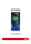
The WR20 Remote Commander is a sophisticated wireless
command centre comprising a rugged, compact, Handset and
SimNet Base Station. It enables you to remotely control all of your
SimNet electronics such as Plotter/Radar, Autopilots
and Instruments. It also controls the VHF with the
advanced features of voice calls.
When paired to a mobile phone it offers the same
operating features as a Bluetooth Handset.
Using the latest Bluetooth technology means that you
are always in control when you want to be.
The WR20 has safety in mind, so it’s very simple to
trigger MOB alerts, make VHF calls on Channel 16 and
switch the Autopilot between Standby and Auto.
To prevent accidental use, the keypad can be locked and
unlocked as required.
Fig 1.1 - Remote
The WR20 Handset has been designed to survive the
Commander
rigours of the marine environment. It has a tough, sealed
body that is fully waterproof and houses an integral Li-Ion
rechargeable battery that is automatically charged whenever it is
placed in its cradle.
Note
A product that is under command from the WR20 can be operated
locally by direct operation at the units own keypad in the normal
way.
Warning
As with all electronic navigational equipment, it is only an
aid to navigation and should not be used as a substitute
for good seamanship. Remember - Maritime law requires
that you keep a good lookout at all times.
9
Introduction
1. INTRODUCTION
Introduction
WR20 Remote Commander
Note
The way that Bluetooth operates means that the maximum distance
between the WR20 handset and its base station is less when using
the handset in audio mode (VHF, intercom or mobile phone modes)
than for data communication. In addition the Bluetooth signal
strength is heavily attenuated by the human head and is optimized
when the handset is in line of sight of the base station
Fig. 1.2 Showing possible reduction in range
depending on how the handset is held
1.2 About this manual
The manual combines operating and installation information for
the WR20. Operation is sub-divided into main product categories
for easy reference. For full operating details of the products under
WR20 control, please refer to their supplied user manual.
1.3 SimNet network system
SimNet is Simrad’s proprietary high speed data bus network. It
provides intelligent sharing of data and control information
between a wide range of marine electronics and instruments.
1.4 Bluetooth
Bluetooth is the name of a wireless technology standard for
connecting devices without the need for cables. It provides a
reliable means of data and audio communication between the
remote Handset and a fixed Basestation.
Note
The separation distance between the Handset and Basestation can
generally be greater for data communication compared with that of
audio communication.
Note
Bluetooth and WiFi technologies operate in the same part of the
radio spectrum. As with any Bluetooth enabled devices working in
a WiFi environment interference can occur. Caution is therefore
10
Introduction
Warning
This equipment communicates wirelessly with the
installed instrument system. It is possible that the
wireless link will fail due to a variety of reasons including,
but not limited to, low battery power, travelling out of
communication range and high levels of RF interference.
Users should be aware that failure of the wireless link
would lead to the inability to control the vessels systems
from the WR20 including an inability to alter pilot course
or make VHF calls. In such circumstances a product can
be operated locally by direct control at the units own
keypad.
11
Introduction
advised when using the WR20 under these conditions as operation
may be impaired and interference may be heard on the VHF audio
channel.
Installation
2 INSTALLATION
2.1 General
Installation
There is no installation required for the Handset which is already
“paired” to the Basestation and ready to use. Installation of the
Basestation and recharge cradle is very simple.
2.2 Installing the recharge cradle
Choose a convenient, dry location to mount the Handset cradle
using the two screws provided. A 12V power cable is supplied and
this should be connected to a suitable supply fused at 2A. Connect
the Red wire to +12V and the Black wire to 0V (Ground).
2.3 Charging the WR20 Handset battery
Push the Handset firmly into the cradle, (Fig. 2.1) and the Handset
battery will charge. If the Handset is switched off the charge status
will be indicated in the display. The unit may be switched on and
will function normally while charging.
Fig. 2.1 - WR20 Charging Cradle
2.4 Installing the Basestation
Careful consideration must be given to the location of the
Basestation to ensure optimum performance.
13
Installation
WR20 Remote Commander
•
Avoid installing behind other electrical and electronic devices as
they may reduce the signal strength and consistency of wireless
communications
•
The Basestation should be at least 2m away from any other
Bluetooth or Wireless LAN (WiFi) transceiver
•
Carbon fibre and steel are strong reflectors of RF signals; they
can severely limit the Bluetooth range depending on the relative
position of the Handset and Basestation
•
Mount in an accessible location for access to pairing functions.
Due to the characteristics of wireless communications a small
alteration in mounting location can make a large difference in
signal strength. A location that is reasonably central in the boat and
reasonably high is favoured.
It is also recommended that the wireless performance is checked
prior to final installation to help decide the optimum location. If
the Handset is to be used as a VHF station the check should also
include audio performance as the range is more limited than the
transfer of data.
The Basestation is connected to the SimNet databus using the cable
supplied. This also supplies power to the Basestation and separate
power is not required. Ensure that the connector on the end of the
cable is in the correct orientation and press firmly into either of the
two Basestation sockets. The spare socket can be used to daisy
chain SimNet to another item of equipment. If the spare socket is
not used insert the supplied blanking plug.
2.5 Connecting to a VHF radio
If the WR20 is to be used as a VHF Handset the Basestation must
be connected to the VHF black box using an accessory cable.
There are two accessory options, the EXPC05 is a 5 meter cable
and the EXPC20 is a 20 meter cable. The end of the cable with the
round connector attaches to the corresponding connector on the
Basestation.
14
Installation
Fig. 2.2 - Terminal wiring
Terminal
Number
1
2
3
4
5
6
7
8
Wire
Colour(s)
Brown
Green
Red
White
Blue
Yellow
Orange
Black
The radio can also be fitted with a Simrad LS80 external speaker
or third party speakers with an impedance of 4 Ohms. If an
external speaker is to be fitted this must be wired directly into the
connector block. Remove the wires from the connector block
terminals 7 and 8 and insulate the bare ends. These wires are are
redundant and not used. Wire the external speaker into the two free
terminals.
Note
The Basestations VHF cable must not occupy the connector in the
VHF black box that is designated Station 1. Station 1 must be
connected to a hardwired VHF Handset or Control Panel.
15
Installation
The other end of the cable has a prewired connector block that
locates in the next available free station in the VHF black box.
Please refer to your VHF user manual for further instructions (Fig.
2.2).
Handset & Keypad Overview
3
HANDSET AND KEYPAD OVERVIEW
3.1 Layout
N
P
Q
R
S
T
U
V
NM
Note
Handset &
Keypad Overview
O
Functions:
1 Speaker/Earpiece
2 PTT (Push-To-Talk)
3 MOB & Soft key 1
4 MOB & Soft key 2
5 4-way NavPad
(Up/Down/Left/Right)
6 Product Selection
7 Menu/Enter
8 PoWER & LIGHTS
9 STANDBY/AUTO
10 Microphone
Fig 3.1 - Wireless
Remote Commander
When using your WR20 Handset for voice communication, hold the
Handset speaker close to your ear as you would a mobile phone.
3.2 PWR/LIGHTS key (Powering on and off)
Press the PWR/LIGHTS key to turn on the WR20 Handset. The
display will show “SIMRAD WR20” and the current software
version number. After approximately 2 seconds the display will
revert to the Product List (see section 5.3)
To turn the Handset off, hold the PWR/LIGHTS key for 3 seconds.
The display will show
“Power Down
Hold PWR Key
for 3 Secs”
17
WR20 Remote Commander
If the PWR/LIGHTS key is released at any time during the power
down sequence, the Handset will revert to whatever it was
displaying prior to pressing the PWR/LIGHTS key.
Handset &
Keypad Overview
3.3 PTT key
The PTT key (Fig. 3.1 Item 2) is reserved for the operation of the
VHF Radio/Intercom (if connected). When pressed the user is able
to Transmit audio from the Handset. When released the user is able
to hear any audio received by the VHF Radio, (as long as the
squelch is open). The user cannot Transmit from the WR20 Handset
if the radio is already in the transmit mode from the main unit.
Note
If the Handset is set to any product page other than the VHF
Radio/Intercom mode, pressing the PTT key for 2 seconds will
change the WR20 to show the VHF Radio/Intercom Product.
3.4 SoftKeys
There are two SoftKeys located directly below the LCD, (Fig 3.1
Items 3 & 4). The function of each SoftKey is shown in the bottom
line of text directly above it.
When the two SoftKeys are pressed simultaneously for over 3
seconds, the MOB (Man Over Board) function is activated, if an
active Simrad navigation product is connected.
3.5 Navigation keys
The circular NavPad, (Fig. 3.1 Item 5) can operate in a variety of
modes depending on product being operated.
3.5.1 4-Way menu navigation
The VW keys are used for picking or highlighting an item in a list.
The W key is used to return to the previous menu (unless it has a
predefined function). Pressing and holding the W key will exit all
menus and return you to the top level menu.
Pressing the X key, (once an item is highlighted), will select it, or
go further into that items sub menus, (unless it already has a
predefined function).
18
Handset & Keypad Overview
3.5.2 4-Way remote key control
Pressing a key on the NavPad has the same effect as pressing a
specified key on the device being controlled and may be
considered a Remote Key Press.
3.6
MENU key (Enter/menu key)
The MENU key (Fig. 3.1 Item 7), has two functions :
3.6.1 Menu function
Pressing the MENU key will bring up the menu associated with
the product that is currently selected on the WR20.
3.6.2 Enter function
When navigating within a menu, once an item has been highlighted,
pressing the MENU key will select that item; this could be
another menu, data item to adjust, or a new product to control.
3.7 Product key
Pressing the PRODUCT key (Fig. 4.1 Item 6), brings up the top level
display showing all products that are available for control by the
WR20.
3.8 STBY/Auto key
The STBY/AUTO key (Fig. 4.1 Item 9), is exclusively reserved for
the Autopilot and will only be usable if there is a WR20
compatible Autopilot connected to the Network.
If the WR20 is controlling any other product, a single press of the
STBY/AUTO key will put the Autopilot into standby mode and give
the WR20 Handset the active control (See section 6.3)
Press and holding the STBY/AUTO key for 2 seconds will put the
Autopilot into Auto Compass mode and give the WR20 Handset
the active control (See section 6.5).
19
Handset &
Keypad Overview
3.5.3 8-Way Remote Control Mode
In this mode, combination keys are allowed. For example, pressing
V and W together will be interpreted as diagonally up and to the
left. This can be useful for positioning the cursor on a Chartplotter
or Radar if connected into the SimNet Network.
WR20 Remote Commander
3.9 PWR/LIGHTS key (Backlight adjustment)
Handset &
Keypad Overview
The backlighting will come on whenever a key is pressed, and will
stay on for 10 seconds. There are two methods for changing the
level of the backlight:
3.9.1 Method one
Press the PWR/LIGHTS key (Fig. 3.1 Item 8) and by using the VW
keys, adjust the light to the required level. The current value will
be shown in the display, (between Off - 9).
Note
If a key has not been pressed for 2 seconds, the display will return
to its previous state.
3.9.2 Method two
Via the “WR20 Setup” menu, see section 4.2.1.1
3.10 Auto KeyLock
If the WR20 has not been used for a predetermined time, the
keypad will lock, a short beep will be heard, and the UNLOCK
SoftKey function will appear.
Note
The display may automatically revert to the Main Menu display at
the same time as the Auto KeyLock starts (depending on the mode
of operation or menu currently activated).
Note
The Auto KeyLock option can be turned on/off and a delay time
entered in the initial WR20 Setup. (See section 4.2.1.5)
Pressing the UNLOCK SoftKey will activate a pop-up box
displaying the text;
“Press Menu To Unlock”
If the MENU key is not pressed within 2 seconds, the display
reverts back to the KeyLocked display.
Pressing MENU will unlock the keypad and return the display to
its unlocked state. The Auto KeyLock timer is reset and starts to
countdown again, (from delay time defined in setup).
20
Handset & Keypad Overview
Note
While unlocked, every key press will reset the countdown timer to
the delay value as defined in “WR20 setup”.
3.11 Battery level indicator
Handset &
Keypad Overview
The battery charge status is indicated by the “ F ” symbol in the
centre lower part of the display. When fully charged the bargraph
contains the letter “F”. When the battery is depleted and requires
recharging the following message (Fig. 3.2) is displayed.
t~êåáåÖ
_~ííÉêóiçï
`Ü~êÖÉe~åÇëÉí
Fig. 3.2 - Battery Low Warning
If the unit continues to be used without being charged the
following message appears when the battery level falls critically
low (Fig. 3.3).
_~ííÉêóiçï
mçïÉêaçïå
áåVëÉÅë
Fig. 3.3 - Powering Down
3.12 Signal indicator
All the time the Handset is in communication with the Basestation
the “ ” symbol is shown in the lower right hand side of the
display. If the signal is lost for any reason, this will disappear.
21
Handset Configuration
4 HANDSET CONFIGURATION
4.1 General
The WR20 has many advanced features that are user configurable
as described below.
4.2 Setup options
To access the setup options first press the PRODUCT key and the
product list will be displayed (Fig. 4.1).
pÉäÉÅí==mêçÇìÅí
Handset
Configuration
W
^mORJN=^ìíçéáäKK
opUMJO=`ä~ëë=a
a~í~m~ÖÉë
toOM=pÉíìé
W
F
Fig. 4.1 - Instrument menu
Using the V or W keys, highlight “WR20 Setup” and press MENU
key to select it (Fig. 4.2).
toOM==pÉíìé
rëÉê=pÉííáåÖë
råáí=pÉäÉÅíáçå
fåëí~ää~íáçå
mÜçåÉ=pÉíìé
W
F
Fig. 4.2 - Setup menu
If there are more items above those being displayed, then V will
be shown in the top left corner of the LCD. If there are more items
below those being displayed, then W will be shown in the bottom
left corner of the LCD.
23
WR20 Remote Commander
Once selected the full list includes:
•
•
•
•
•
•
Handset
Configuration
Note
User settings
Unit Selection
Installation
Phone Setup
Radio Setup
Select Radio
“Select Radio” will only appear if more than one VHF radio is present on
the SimNet network.
4.2.1 User settings
Selecting the “User Settings” option from the Setup list opens the
following menu (Fig.4.3).
rëÉê==pÉííáåÖë
iáÖÜí=iÉîW
`çäçìêW
iáÖÜí=qáãÉW
`çåíê~ëíW
W
V
tÜáíÉ
NMë
OQ
F
Fig. 4.3 - User Settings
Note
The same menu will appear when the PWR/LIGHTS key is pressed.
The full list includes:
•
•
•
•
•
•
Light Lev
Colour
Light Time
Contrast
Auto KeyLock
KeyBeep
4.2.1.1 Light level
Highlight “Light Lev” and then use the X key to highlight the light
level value. Use the V or W keys to adjust to the desired level
between Off - 9.
24
Handset Configuration
To return to the user settings list press W.
4.2.1.2 Colour
Highlight “Colour” and then use the X key to highlight the colour
value. Press the V or W key to toggle the colour between “Red”
and “White”.
To return to the user settings list press W.
To return to the user settings list press W.
4.2.1.4 LCD contrast
Highlight “Contrast” and then use the X key to highlight the
contrast value. Use the V or W keys to adjust the Display Contrast
to a suitable level between 0 - 40.
To return to the setup list press W.
4.2.1.5 Auto KeyLock
Highlight “Auto KeyLock” and then use the X key to highlight the
time delay interval. Use the V or W keys to toggle the delay
interval between Off, 30s or 60s.
To return to the setup list press W
4.2.1.6 KeyBeep
An audible KeyBeep can be switched on or off. Highlight
“KeyBeep” and then use the X key to highlight the current setting.
Use the V or W keys to toggle the KeyBeep between On or Off.
To return to the setup list press W.
25
Handset
Configuration
4.2.1.3 Light Time
Following a key press the backlights come on for a predefined
period. This period can be adjusted by highlighting “Light Time”
and then using the X key to highlight the timeout value. Press the
V or W key to select a time delay of 10s, 20s or 30s for the lights
to remain on after a key press.
WR20 Remote Commander
4.2.2 Unit selection
Selecting “Unit selection” from the “WR20 Setup” menu will
display data in predefined units of measurement, however, these
can be changed to meet individual needs (Fig. 4.4).
råáí==pÉäÉÅíáçå
Handset
Configuration
aÉéíÜW
_ç~í=péÉÉÇW
táåÇ=péÉÉÇW
aáëí~åÅÉW
W
j
hq
hq
hj
F
Fig. 4.4 - Unit selection options
The full list includes:
•
•
•
•
•
Depth
Boat Speed
Wind Speed
Distance
Temperature
4.2.2.1 Depth units
Highlight “Depth” and then use the X key to highlight the current
depth unit. Use the V or W keys to toggle between feet and meters.
To return to the setup list press W.
4.2.2.2 Boat speed units
Highlight “Boat Speed” and then use the X key to highlight the
current units. Use the V or W keys to change between knots, miles
per hour and kilometres per hour.
To return to the setup list press W.
4.2.2.3 Wind speed units
Highlight “Wind Speed” and then use the X key to highlight the
current units. Use the V or W keys to change between knots,
kilometers per hour, miles per hour, meters/sec and Beaufort.
To return to the setup list press W.
26
Handset Configuration
4.2.2.4 Distance units
Highlight “Distance” and then use the X key to highlight the
current units. Use the V or W keys to change between nautical
miles, statute miles and kilometres.
To return to the setup list press W.
To return to the setup list press W.
4.2.3 Installation
Selecting “Installation” from the “WR20 Setup” menu provides the
following options (Fig 4.5).
fåëí~ää~íáçå
m~áê=íç=t_OM
mêçÇìÅí=fåÑç==
oÉëÉí=_Lpí~íáçå
oÉëÉí=aÉÑ~ìäíë
W
F
Fig. 4.5 - Installation options
The full list includes:
•
•
•
•
•
Pair to WB20
Product Info
Reset B/Station
Reset Defaults
S/W Upgrade
4.2.3.1 Pair to WB20
When “Pair to WB20” is selected from the “Installation” menu the
WR20 enters pairing mode. For more information on pairing, refer
to section 12.2.
To return to the setup list press W.
27
Handset
Configuration
4.2.2.5 Temperature units
Highlight “Temperature” and then use the X key to highlight the
current units. Use the V or W keys to toggle between °Fahrenheit
and °Centigrade.
WR20 Remote Commander
4.2.3.2 Product info
When “Product Info” is selected from the “Installation” menu, the
Software Version and Serial Number is displayed for both the
Handset and Basestation (Fig. 4.6).
mêçÇìÅí==fåÑç
Handset
Configuration
toOM
toOM
t_OM
t_OM
ptW
pkW
ptW
pkW
MMKPN
t`MMMMVP
MMKOO
t`MMMMVQ
F
Fig. 4.6 - Product Info
To return to the setup list press W.
4.2.3.3 Reset B/station
The BaseStation is always powered on when it is connected to a
live SimNet system. The “Reset B/Station” function essentially
switches the BaseStation off and then on again. This has the
advantage that it can be done remotely from the handset no matter
where the BaseStation is mounted.
To switch the BaseStation off and then on again select "Reset
B/Station" from the "Installation" menu and press MENU. The reset
is executed immediately. Press W to return to the previous menu.
4.2.3.4 Reset defaults
This function will set user configurable variables back to the
factory preset values.
4.2.3.5 S/W upgrade
In the event that software upgrades become available these can be
downloaded to the WR20 over Bluetooth. Instructions for
downloading will be supplied with the software upgrade.
4.2.4 Phone setup
From the “WR20 Setup” menu your WR20 can be paired with
many makes of mobile phone that feature Bluetooth Headset
support. The “Phone Setup” menu allows this feature to be enabled
28
Handset Configuration
– in which case “Mobile Phone” will appear as a selectable item in
the list of products when the PRODUCT key is pressed.
Selecting the “Phone Setup” menu will display whether Mobile
Phone support is switched on or off. To change the status, use the
X key to highlight the current status and then use the V or W keys
to adjust accordingly.
To return to the setup list press W. For information on making and
receiving calls via mobile phone please refer to section 10.
Handset
Configuration
4.2.5 Radio Setup
From the “WR20 Setup” menu select “Radio Setup”.The WR20
will only control a VHF radio whose black box is connected
directly to the wireless base station. If there is no direct
connection, the radio can be disabled from the network so that it
no longer appears in the product list.
From the “Radio Setup” menu the control of the radio can be
enabled/disabled using the ON/OFF SoftKey (Fig 4.7).
o~Çáç==pÉíìé
o~Çáç=bå~ÄäÉÇ
F
lkLlcc
Fig. 4.7 - Radio Setup
To return to the setup list press W.
Note
4.2.6 Select Radio
This option will only be available if there is more than one VHF
Radio on the SimNet network.
From the “WR20 Setup” menu press “Select Radio”. If more than
one VHF radio is present on the SimNet network, each one will be
identified in the product listing with a unique instance number as
shown in (Fig. 4.8).
29
WR20 Remote Commander
pÉäÉÅí==o~Çáç
opUMJN=`ä~ëë=a
opUMJO=`ä~ëë=a==
F
Fig. 4.8 - Selecting a radio
Handset
Configuration
The WR20 will only control the VHF whose black box is
connected directly to the wireless base station. If this is RS80-1
Class D in the example above then this radio must be selected from
the list. All VHF operation from the handset will then control the
selected radio.
From the “Select Radio” menu select the appropriate radio from
the list, and press MENU.
To return to the setup list press W.
30
Product Selection
5 PRODUCT SELECTION
5.1 Product recognition
Only WR20 compatible products will be available for selection.
5.2 Selecting from a list
Press the PRODUCT key to display a list of products connected to
the SimNet Network (Fig. 5.1).
V pÉäÉÅí==mêçÇìÅí
W
^ìíçéáä=K=K
`ä~ëë=a
k^spq^q=K=K=
fåëí=póë
F
Fig. 5.1 - Product List
Use the V or W keys to highlight the product you require.
If there are more items above those being shown, then V will be
displayed in the top left corner of the LCD. If there are more items
below those being shown, then W will be displayed in the bottom
left corner of the LCD.
Pressing the MENU or key will select the product. The display
will now show the current status of that selected Item.
Pressing the key will return you to the previous menu.
If a product is not available the display will show the product name
at the top of the display and the message.
“Product Not Available”
A product will become “Not Available” if it is under control from a
local control at the same time you wish to access it from your handset.
5.3 Disabling remote control
It may be desirable to inhibit remote control of specific products in
the network. Details for enabling or disabling remote control can
be found in the product’s operating instructions.
31
Product Selection
^mORJN
opUMJO
`uPQJO
fpNO
Autopilot
6 AUTOPILOT
6.1 General
The ability of the WR20 to control many different models of
Simrad Autopilots may mean that some of the functions shown in
this manual will not be relevant to the model you have purchased.
However, the way the information is shown in the display will
apply to current and future models. Please refer to the manual that
came with your Autopilot for further information.
6.2 Display
Select the Autopilot you wish to control from the product menu.
An example Autopilot Standby display (AP25) is shown in (Fig.
6.1), with current compass heading, Thruster ‘active’ symbol (if
available), Rudder Angle Indicator and ‘Inactive’ symbol, shown
by a “ ” in the top right corner of the display. At this stage you do
not have control over the selected Autopilot.
Autopilot
Thruster
symbol
^mORJN
N
pq^ka_v
Heading
eb^afkdW NPS°j
m• • • • • • MR Ì • • • • • p
Inactive symbol
(Not in control)
Operational mode
Rudder Angle
Indicator
F
Fig. 6.1 - Standby mode
(Inactive)
33
WR20 Remote Commander
6.3 Standby mode
To gain control of the Autopilot, press STBY/AUTO key. The
“Inactive” symbol disappears from the display, and the MODE
SoftKey function appears (Fig. 6.2).
^mORJN
N
pq^ka_v
eb^afkdW NPS°j
m• • • • • • MR• • • • • • p
F
jlab
Fig. 6.2 - Standby mode (Active)
Autopilot
In Standby mode pressing the W Port or X Starboard NavPad key
will control the rudder. If either key is pressed, the display will
indicate “Power Steer” (Fig. 6.3).
^mORJN
N
pq^ka_v==kcr
W mçïÉê=píÉÉê===X
eb^afkdW NPS°j
P• • • • • • 15 ÌÌÌ• • • S
F
jlab
Fig. 6.3 - Powersteer display
Note
As rudder is added in either direction, the display will change to
show a single arrow “Ì” and a double arrow “ÌÌ”.
6.4 Steering modes
Pressing the MODE SoftKey enters the steering mode menu,
“Standby” and “Auto Compass” will be listed as standard. Further
options such as Auto NoDrift, Auto Nav and Auto Wind, may be
listed depending on the settings of the Autopilot itself (Fig. 6.4).
Use the V or W keys to scroll through the menu options. Press the
MENU key to select the mode you want to enter.
34
Autopilot
^mORJN
N
pí~åÇÄó
^rql=`çãé~ëë
^rql=kçaêáÑí
`^k`bi
F
Fig. 6.4 - Steering mode
Pressing CANCEL returns you to the previous mode
Note
Throughout this chapter, Pressing the MODE SoftKey when
available will open the “Steering Mode” menu.
6.5 Auto Compass mode
^mORJN
N
^mORJN
N
^ìíç==`çãé~ëë
^ìíç==`çãé~ëë
`lropbW
eb^afkdW
aladb
F
NPS
NPV °j
jlab
Fig. 6.5 - Auto Compass
(Powerboat)
`lropbW
eb^afkdW
q^`h
F
NPS
NPV °j
jlab
Fig. 6.6 - Auto Compass
(Sailboat)
Pressing the W or X Nav key allow you to make course
adjustments in 1 degree increments. Holding the key down, makes
changes at a rate of 5 degrees per second, until released.
6.5.1 DODGE (Powerboat)
Press the DODGE Softkey to initialise a Dodge. The display will
change to show “DODGE” flashing in the display (Fig. 6.7).
Enter a direction for the Dodge by pressing the W or X Nav key.
The amount of turn will increase the longer the key is held down.
35
Autopilot
Selecting the “Auto Compass” mode from the menu, the following
information will be displayed (Fig. 6.5) for powerboats and (Fig.
6.6) for sailboats.
WR20 Remote Commander
^mORJN
N
aladb
^rql `ljm^pp
`lropbW========NPV
W
mêÉëë=====X
`^k`bi
F
Fig. 6.7 - DODGE (Powerboat)
Note
Pressing the CANCEL SoftKey returns you to the Auto Compass.
Autopilot
6.5.2 TACK (Sailboat)
Press the TACK SoftKey to initialise a Tack.
Warning
Gybing is not recommended when in Auto Compass
mode as the Autopilot has no reference to the point
at which the wind changes from one tack to the other.
The display now shows “Tack” flashing and “W Press X”
indicating an input is required, Port or Starboard (Fig. 6.8).
^mORJN
N
q^`h
^rql `ljm^pp
`lropbW========NPV
W
mêÉëë=====X
`^k`bi
F
Fig. 6.8 - Tack display (Sailboat)
Pressing either the W or X Nav key will initiate a course change,
and the boat will start to turn in the selected direction.
The amount of turn is dictated by the Autopilot Course computer
and not the WR20 Handset.
Note
If no directional input is given within 5 seconds, the display will
return to Auto Compass Mode display.
36
Autopilot
Pressing the CANCEL SoftKey within 5 second cancels the Tack
and returns the boat to the original course.
6.6 Auto NoDrift mode
Selecting the “Auto NoDrift” Mode from the menu, the following
information will be displayed (Fig. 6.9).
^mORJN
N
^ìíç==kçaêáÑí
`lropbW
eb^afkdW
aladb
F
NPS
NPV°j
jlab
Fig. 6.9 - Auto NoDrift display
6.6.1 DODGE
Refer to section 6.5.1
6.7 Auto Nav mode
As the display is loaded into the WR20 Handset, it will make a
short notification beep.
The Auto Nav Prompt display shows all the relevant information
for this Mode (Fig.6.10).
^mORJN
N
båÖ~ÖÉ==k~î
oqmMMMN
tmW
_od=tLtW
NVM °j
`pb=`edW
pNMR=
`^k`bi
F
lh
Fig. 6.10 - Auto Nav Prompt
display
37
Autopilot
Pressing the W or X NavPad key makes fine course adjustments in
1 degree steps. Holding the key down, makes changes at a rate of
5 degrees per second, until released.
WR20 Remote Commander
The system is waiting for confirmation to enter Nav mode. Press the
OK SoftKey to confirm course change and engage Auto Nav Mode.
Press the CANCEL SoftKey to Cancel the Engage Auto Nav
Prompt display and return to the previous Mode.
Once confirmed and the Auto Nav Mode is engaged the display
shows all relevant information (Fig. 6.11).
^mORJN
N
tmW
uqbW
^ìíç==k~î
oqmMMMN
MKMNkj
aladb
F
jlab
Autopilot
Fig. 6.11 - Auto Nav display
6.7.1 DODGE
Refer to section 6.5.1
Note
The “Engage Nav” prompt also appears when approaching a
waypoint. This is a demand for a course change accept when the
change onto the next leg exceeds the course change limit (10°, 20°
or 30°) as set in the Autopilot installation setup.
WARNING
If the course change is not acknowledged, the
Autopilot will continue on its present heading. This
could result in damage to your vessel and serious
injury.
6.8 Auto Wind mode
The Auto Wind Display shows all of the relevant information for
this Mode (Fig. 6.12).
To adjust the wind angle to Port/Starboard, pressing the W or X
Nav key will make fine adjustments in 1 degree steps.
Press and holding the Nav key down, changes the wind angle at a
rate of 5 degrees per second, until released.
38
Autopilot
^mORJN
N
^ìíç==táåÇ
tLpqbboW
^mm=tL^W
q^`h
F
NPS
mMQR
jlab
Fig. 6.12 - Auto Wind Mode
Note
6.8.1 TACK/GYBE mode
The function of the left SoftKey is dependent on angular wind data
received by the Autopilot. “TACK” is only shown when sailing into
wind and “GYBE” is only shown when sailing with the wind.
To initialise a Tack/Gybe, press the TACK/GYBE SoftKey.
Autopilot
The display now shows “TACK” or “GYBE” flashing on the
screen, Press OK to confirm this action (Fig. 6.13).
^mORJN
N
^ìíç=táåÇ
q^`h
`^k`bi
F
lh
Fig. 6.13 - Tack/Gybe display
Note
If you do not confirm this within 5 seconds the display will return
to Auto Wind Mode display.
Once the Tack or Gybe has been confirmed the boat will start to
turn. The rate of turn is dictated by the Autopilot Course computer
and not the WR20 Handset.
At this stage, pressing the CANCEL SoftKey within 5 second
cancels the Tack or Gybe and returns the boat to the original tack.
Once the 5 seconds has elapsed, the display will return to the Auto
Compass Mode display.
39
WR20 Remote Commander
6.9
Autopilot Alarms
The Autopilots are programmed to provide essential alarms. The
alarm message will appear on the WR20, and depending on the
operating circumstances the alarm may inhibit some features of the
WR20 until the alarm condition is cleared.
Note
For safety reasons an alarm can only be cleared at the Autopilot
control head itself and not from the WR20 Handset.
An audible alarm will sound on the WR20 for as long as the Alarm
condition exists, or until the user 'Mutes' the Alarm sound or the
condition is cleared at the Autopilot control head.
6.9.1 WR20 Alarm Displays
Once an Alarm 'On' Condition has been received by the WR20, a
pop-up Alarm display will be shown (Fig. 6.14).
Autopilot
^mORJN
N
^i^oj
lcc=`lropb
`eb`h=j^fk=rkfq
jrqb
F
Fig. 6.14 - Autopilot off course
If the WR20 was previously controlling the Autopilot pressing the
MUTE SoftKey will silence the alarm, however, the WR20 will
not be usable until the alarm condition is cleared at the Autopilot
control head. If the WR20 was previously controlling an
instrument other than an Autopilot then pressing MUTE SoftKey
will silence the alarm and the WR20 display will return to the
instrument under control. It will not be possible to select the
Autopilot from the WR20 until the alarm condition is cleared at the
Autopilot control head. In both cases, when the alarm is cleared the
WR20 display will briefly show "ALARM CLEARED" before
resuming normal operation.
6.9.2 Autopilot 'Volvo IPS Override Warning'
When the Autopilot is overridden from the helm of an IPS steering
40
Autopilot
system the following message is displayed for 2 seconds (Fig. 6.15).
^mORJN
N
t^okfkd
fmp=lsboofab
jrqb
F
Fig. 6.15 - Volvo IPS override
warning
41
Autopilot
If the WR20 was previously controlling the Autopilot it will no
longer be usable until the override condition is cleared. If the
WR20 was previously controlling an instrument other than an
Autopilot then following the warning message the WR20 display
will return to the instrument under control. It will not be possible
to select the Autopilot from the WR20 until the override condition
is cleared.
VHF Radio/Intercom
7 VHF RADIO/INTERCOM
7.1 General
The WR20 acts as an additional station to your VHF. Note that a
separate cable is required to interface the WR20 Basestation to the
VHF black box, (Section 2.4). The WR20 Handset operates the
major functions of the VHF including changing channels, adjusting
the volume of an attached external loudspeaker and adjusting the
radio squelch. In addition intercom calls can be received and
initiated between the WR20 Handset and any other station.
7.2 Display
If there is more than one radio on the network please refer to
Section 4.2.4 Radio Selection. Select the connected Radio from the
product list or alternatively by pressing and holding the PTT key
for 2 seconds.
An example Radio display (RS80-1) is shown, the following
default Information is displayed (Fig. 7.1):
4
6
8
10
3
opUMJN
N
_ sli
5
pni=`
ORt====fkq====oñ
7
`e==NM
9
Nt
VHF Radio
Intercom
2
1
`eNS
11
Fig. 7.1 - VHF Main display
1. Title of left bargraph Item 6 (Volume)
2. Current device under WR20 control
3. Title of right bargraph Item 9 (Squelch)
4. Current transmission power
5. Channel Set
6. Bargraph showing volume level
7. Current status Tx/Rx
8. Active channel
9. Bargraph showing Squelch level
10. Left SoftKey function, toggle 1W/25W transmitter power
11. Right SoftKey function ‘Select emergency channel 16
43
WR20 Remote Commander
Note
Press PRODUCT at any time, to see the product list.
7.3 Changing channels
To select the required channel press the
or decrement the channel number.
or
keys to increment
7.4 Volume & squelch adjustment
To select the volume of the external loudspeaker, press the W key.
The display now shows “VOL” highlighted in the display. Use
or to adjust the volume to the required level.
To select the squelch, press the X key. The display now shows the
“SQL” highlighted in the display. Use or to adjust the
squelch setting.
VHF Radio
Intercom
Adjusting “VOL” or “SQL” is only available for 3 seconds - if or
are not pressed within this time, their function reverts to channel select.
While the WR20 is in the radio mode, the “VOL” and “SQL” level
will be displayed as a bargraph on the left and right hand sides of
the display respectively.
7.5 PTT (Push to talk)
Pressing the PTT key on the side, will enable the Remote
Commander to transmit voice, via the internal microphone, on the
selected channel. “Tx” will be shown in the display, and you will
hear the reply on the internal speaker when the PTT is released.
7.6 Selecting transmission power
Press the 1W/25W SoftKey to toggle between 1W/25W transmitter
power.
7.7 Selecting emergency channel 16
To select Channel 16 press the CH16 SoftKey. Channel16 is now
the active channel and shown in the centre of the display.
Press the
44
or
key to return to another channel .
VHF Radio/Intercom
7.8 Radio menus options
Pressing the MENU key will display a menu of VHF radio
options (Fig. 7.2).
fkqbo`lj
sec=o~Çáç
pí~íáçå=N
pí~íáçå=O
pí~íáçå=P
F
Fig. 7.2 - Radio Options Menu
Use the or keys to scroll through the options and highlight
the one you require. Press the MENU or X key to enter that
option.
7.8.1 VHF radio
Selecting this option will return you back to the radio display.
7.8.2 Call individual station (Intercom)
It is possible to make an intercom call to a selected position from a
handset.
To select an individual station, use the or keys to highlight
the required station and press MENU or X key (Fig. 7.3).
Once selected, the display will show the station being called. On
reply, press the PTT key to transmit your message.
Press the END CALL SoftKey or W if activated by mistake or the
call has finished.
45
VHF Radio
Intercom
If the Radio Options menu has more items above those being
displayed, then
will be shown in the top left corner of the LCD.
If there are more items below those being displayed, then
will
be shown in the bottom left corner of the LCD.
WR20 Remote Commander
fkqbo`lj
`~ääáåÖ
pí~íáçå=N
bka=`^ii F
Fig. 7.3 - Intercom
7.8.3 Call all stations (Intercom)
To call all stations, use the or keys to highlight the “All
Stations” option. This is a broadcast and does not require a
response by an end user. Press the PTT key to transmit your
message.
VHF Radio
Intercom
Pressing the END CALL SoftKey will terminate the “All Stations”
Intercom call.
46
NavStation
8. NAVSTATION
8.1 General
The WR20 Handset is able to control all of the major functions of
WR20 compatible Chartplotters, Fishfinders and Navstations.
The WR20 controls these products using both MENU selection and
cursor control. Under MENU selection control options are
presented in the WR20 screen. In cursor control the WR20 NavPad
has the same functionality as the cursor keys on the Navstation.
The availability of features, SoftKey functions, menu items and
their order, will be determined by the version of software
controlling the primary product under WR20 control. For more
information please refer to the product’s user manual.
8.2 Display
Select the Navstation you wish to control from the product list. The
CX34 is used here as an example.
The first display (referred to as the Top Level Display), allows
selection of the operating mode (Fig 8.1).
`uPQJN
N
+W
NavStation
W-
o^a^o
`e^oq
b`el
mfilq
hbv
F
jbkr
Fig. 8.1 - PAGE options
Using the V or W keys, highlight the mode you want and press
MENU or X key to select it.
Use the W or X Nav keys on the WR20 Handset to go up/down in
range on the Navstations primary display.
Note
Pressing the EXIT SoftKey from any of the submenu’s, will
sequentially return you to the Top Level display (as shown in Fig 8.1).
47
WR20 Remote Commander
8.3 Navstation control
Press the MENU SoftKey to bring up the four menu options. (Fig. 8.2):
W-
`uPQJN
N
+W
jÉåì_~ê
^ag==jÉåì
nìáÅâ==jÉåì
mto==jÉåì
`roplo
F
bufq
Fig. 8.2 - Menu options
8.3.1 MENU option
“MenuBar” - Equivalent to the MENU key on the main device.
“ADJ Menu” - Equivalent to the ADJ key on the main device.
“Quick Menu” - Equivalent to the ENT key on the main device.
“PWR Menu” - Equivalent to the PWR key on the main device.
Use the VW keys, highlight the required menu and press MENU
to select it.
NavStation
The corresponding menu will appear on the screen of your primary
product and items can be selected using the NavPad.
Press the EXIT SoftKey to switch off the menu in the Navstation
display.
Press the CURSOR SoftKey if cursor control is required. Using
the VWWX of the NavPad (Fig. 8.3), you can control the cursor
on the display of your primary product.
`uPQJN
N
W `ìêëçê==X
W `çåíêçä V
tfk
F
bufq
Fig. 8.3 - Cursor control
48
NavStation
Pressing the WIN SoftKey allows you to toggle between the active
window combinations on the primary products display.
8.3.2. KEY option
Additional primary functions are provided by pressing the KEY
SoftKey. This provides access to the functions shown in (Fig 8.4).
W-
`uPQJN
N
+W
dlql
milq
tfk
`io
`roplo
F
bufq
Fig. 8.4 - KEY options
These options provide the same functions as the equivalent keys on
the primary product. (Refer to user manual)
Cursor control can also be gained at this stage by pressing the
CURSOR SoftKey.
8.4 MOB function
NavStation
Simultaneously pressing the two MOB SoftKeys for over 3
seconds activates the MOB (Man Over Board) function. The
display will change, as shown in (Fig.8.5), and a few short beeps
will be heard from the Handset.
`uPQJN
N
buqbok^i=jl_>
pq^oq
F
`ib^o
Fig. 8.5 - MOB
If activated by mistake, press the CLEAR SoftKey to cancel the MOB.
Press the START SoftKey to confirm and start MOB navigation.
49
WR20 Remote Commander
All of the relevant information for an efficient rescue operation
will be shown on the NavStations primary display.
NavStation
To turn off an active MOB, please refer to the NavStation user
manual.
50
Instruments
9 INSTRUMENTS
9.1 General
The WR20 Remote Commander can be used to control all of the
major functions of any WR20 compatible instrument that is
attached to the network.
Note
In order to view Instrument data on the WR20 display, please refer
to section 11.2.
9.2 Display
After selecting “INST SYS” from the product list, the WR20
display will show a list of instruments attached to the network
(Fig. 9.1).
V
pÉäÉÅí==fåëí
fpNOJM=tfka
fpNOJM=`lj_f
fpNOJM=abmqe
fpNOJM=jbd^
W
F
Fig. 9.1 - Instrument selection menu
Using the V or W keys, highlight the instrument you want to
control and press the MENU or key to select it.
Once selected, the display shows a graphical representation of the
instrument keypad, together with the corresponding keys on the
WR20 handset that control their functions (Fig 9.2).
In the example shown, the “LIGHTS” key on the Depth instrument
is controlled by the key, and the “DEPTH” alarm by the right
hand SoftKey on the handset.
51
Instruments
If the list of attached instruments has more items above those being
displayed, then V will be shown in the top left corner of the LCD.
If there are more items below those being displayed, then W will
be shown in the bottom left corner of the LCD.
WR20 Remote Commander
fpNOJM
M=abmqe
LIGHT SHALL DEEP
INFO
H
Fig. 9.2 - Depth Instrument
The selected instrument will show “CTRL” flashing briefly in its
display.
The text legend shown on the keys in the WR20 display will
emulate the keys of the selected instrument.
For information on the functionality of each instruments keys,
please refer to the relevant instrument user manual.
When remotely controlling an instrument from the WR20, the result
of a key press can be seen in that selected instrument and not in
the WR20 display.
Note
To select a different instrument press
the list.
Instruments
Note
52
MENU key and select from
Mobile Phone
10 MOBILE PHONE
10.1 General
Your WR20 can be paired with many makes of mobile phone that
feature Bluetooth Headset support. The functions that are available
will dependent on the specific phone used. Note that when operating
in this mode the WR20 is disconnected from the Basestation and
will automatically reconnect when the PRODUCT key is pressed.
10.2 Enabling mobile phone connectivity
Mobile Phone support can be switched on or off in the “Phone
Setup” menu within the “WR20 Setup” menu (4.2.5). When support
is enabled “Mobile Phone” appears as a selectable product in the
Product list screen. When disabled it does not appear in the product
list and the WR20 cannot be used as a remote phone handset.
10.3 Pairing the WR20 with a mobile phone
Ensure that “Mobile Phone” is enabled in the “Phone Setup” menu
(Section 4.2.5). When the PRODUCT key is pressed “Mobile Phone”
will appear at the end of the Product list.
Note
Use the V or W keys to highlight the “Mobile Phone” option, and
press the MENU key to select it. The display changes as shown
in (Fig. 10.1).
If your phone has previously been Paired, the message “Phone not
jçÄáäÉ==mÜçåÉ
W
F
Mobile Phone
sçäìãÉ W
mÜçåÉ==åçí==m~áêÉÇ
EmêÉëë==jbkrF
slf`b
af^iifkd
Fig. 10.1 - Mobile Phone Options
Paired (Press MENU)” will not appear, and you are able to make
or answer a call.
Note
“VOICE DIALING” SoftKey will only be shown if your mobile
phone supports this function.
53
WR20 Remote Commander
Press the MENU key to Pair your phone to the Handset. The
display changes (Fig. 10.2).
mÜçåÉ==jÉåì
m~áê==íç==éÜçåÉ
F
Fig. 10.2 - Phone Menu
Note
If your phone has previously been Paired, “Delete Pairing” will
also be shown as a second option in the Phone Menu above.
Highlight, “Pair to Phone” and press the
MENU key to select it.
The Handset enters pairing mode, it generates and displays a
security PIN (Fig.10.3).
m~áêáåÖ
mfk==Z==NOPQ
rëÉ== ãçÄáäÉ== éÜçåÉ
íç== ëÉ~êÅÜ== C== é~áê
íç==toOM==Ü~åÇëÉíK
F
Mobile Phone
Fig. 10.3 - Pairing
Following the instructions for the particular mobile phone being
used, execute a search for Bluetooth devices.
Select the “WR20” on the mobile phone and when prompted enter
the PIN (passcode) on the mobile phone.
Once paired, the WR20 Handset will support the same features as a
Bluetooth headset which will be dependent on the phone used. The
WR20 display reverts to the Mobile Phone display.
54
Mobile Phone
10.4 Making/receiving calls
From the top level product list select “Mobile Phone”.The display
will change as shown in (Fig. 10.4).
jçÄáäÉ==mÜçåÉ
W
sçäìãÉ W
F
slf`b
af^iifkd
Fig. 10.4 - Mobile Phone Options
For the features available please refer to the phone’s user manual.
The following common features may be used as a guideline.
The audio volume can be controlled using the V or W
keys on the NavPad.
•
Calls initiated on the mobile phone will be simultaneously
available on the WR20.
•
Calls can be ended by pressing the
the WR20.
•
Incoming calls can be answered directly on the WR20 by
pressing the
SoftKey.
•
Pressing the
SoftKey will initiate a call to the last
number dialled.
•
The VOICE DIALING SoftKey can be used with phones
that support voice dialling and have voice tags already set.
Press the VOICE DIALING SoftKey and follow the same
procedure as for your mobile phone.
SoftKey on
Mobile Phone
•
55
WR20 Remote Commander
10.5 Range
Most mobile phones support Bluetooth Class 11 which have a
more limited range than Class 1. This means that the distance
between the mobile phone and WR20 Handset should be within the
same range limits as for a Bluetooth Headset (typically up to 10m).
10.6 Reconnect to Basestation
To reconnect to the WR20 Basestation at any time press the
PRODUCT key. This will hangup any calls in progress.
Mobile Phone
Note
56
It is not necessary to press the PTT key when using the WR20
Handset in mobile phone mode.
Data Displays
11 DATA DISPLAYS
11.1 General
The WR20 can display data from various sources on the network
simultaneously. The display is user configurable both in terms of
the type of data to be shown and also the number of lines of data in
the display (maximum of 4). If only 1 or 2 Data Items are to be
displayed, then the size of the displayed data is enlarged. The
units in which data is displayed are also selectable, please refer to
Section 4.2.2.
11.2 Display
After selecting “DataPages” from the product menu, the WR20
display will show a list of available pages (Fig. 11.1).
V
a~í~m~ÖÉë
m~ÖÉ=O
m~ÖÉ=P
m~ÖÉ=Q
m~ÖÉ=R
W
bafq
F
lkLlcc
Fig. 11.1 - DataPages menu
The pages are pre-configured at the factory however they can be
customised as required.
Using the V or W keys, highlight the one you want to view and
press the MENU or key to select it.
Once a page has been selected, the display will show the Simrad Group
data associated with that page. An example is shown in (Fig. 11.2).
To scroll to the next data page press the V or W key.
57
Data Displays
If there are more pages above those being displayed, then V will be
shown in the top left corner of the LCD. If there are more pages
below those being displayed, then W will be shown in the bottom
left corner of the LCD.
WR20 Remote Commander
a~í~m~ÖÉ==O
NNKO j
TKM hq
NPM° j
abmqeW
_pmbbaW
eb^afkdW
F
Fig. 11.2 - An example DataPage
Note
Information from sources not controllable by the WR20 will be
displayed if the data has been converted to SimNet format. For
example, data from an NMEA source converted to SimNet using an
AT10 converter.
11.2.1 Selecting DataPages for viewing
For clarity and ease of use, DataPages can be turned off if not
required, so that when scrolling through them, only the ones you
wish to view are displayed.
From the “Edit DataPage” menu (Fig. 11.1), highlight the DataPage
you want to turn on or off and press the ON/OFF SoftKey. This
will toggle the state of that selected DataPage between “ ” (On),
and “ ”(Off).
11.3 Configuring DataPages
Data Displays
DataPages can be customised for user preference. Configuration
screens can be reached in one of two ways. Directly from the
“DataPage” menu by selecting the DataPage to be configured and
then pressing the EDIT SoftKey as shown in (Fig. 11.1).
Alternatively any DataPage that is being viewed can be modified
by pressing the MENU key. Either method will take you to the
screen shown in (Fig. 11.3)
58
Data Displays
bÇáí==a~í~é~ÖÉ==O
t~íÉê=aÉéíÜ
_ç~í=péÉÉÇ
eÉ~ÇáåÖ=j~Ö
objlsb F
^aa
Fig. 11.3 - Edit DataPage screen
11.3.1 Adding a DataPage item
On entering the “Edit DataPage” screen, the display shows the
current data. Press the ADD SoftKey and the display changes to
show a list of “Data groups” available (Fig. 11.4).
a~í~==dêçìéë
eÉ~ÇáåÖ=a~í~
k~îáÖ~íáçå
táåÇ=a~í~
péÉÉÇ=C=içÖ
W
F
Fig. 11.4 - Data group list
The available groups are:
Heading Data
Navigation
Wind Data
Speed & Log
Environmental
Depth Data
Pilot Data
Position
Using the V or W keys, highlight the required Data Group and
press the MENU or key to select it. This brings you to a submenu of items for that selected Data Group (Fig. 11.5). For a full
list of Data Group Items refer to page 62.
59
Data Displays
•
•
•
•
•
•
•
•
WR20 Remote Commander
k~îáÖ~íáçå
`êçëë=qê~Åâ=bêê
_É~êáåÖ=íç=tm
táåÇ=a~í~
péÉÉÇ=C=içÖ
W
F
Fig. 11.5 - Selected group item list
Using the V or W keys, highlight the Data Item required, and
press the MENU or key to accept. This will return you to the
“Edit DataPage” screen.
To continue adding items, repeat the stages from the beginning of
this section (11.3.1) or to accept the change and display the new
DataPage press the key (Fig.11.6).
a~í~é~ÖÉ==O
NNKO j
TKM hq
NPM° j
NOR° j
abmqeW
_pmbbaW
eb^afkdW
_qtW
F
Fig. 11.6 - New DataPage
11.3.2 Exchanging a DataPage item
On entering the “Edit DataPage” screen (Fig 11.3), the display
shows the current data. Use the V or W keys to highlight the Data
Item you want to exchange and press the MENU key (Fig. 11.7).
Data Displays
bÇáí==a~í~é~ÖÉ==O
t~íÉê=aÉéíÜ
_ç~í=péÉÉÇ
eÉ~ÇáåÖ=j~Ö
_É~êáåÖ=íç tm
objlsb F
Fig. 11.7 - Edit DataPage screen
60
Data Displays
The display changes to show the list of Data Groups available,
highlighting by default, the Data Group which the current Data
Item being exchanged comes from (Fig. 11.8).
a~í~==dêçìéë
eÉ~ÇáåÖ=a~í~
k~îáÖ~íáçå
táåÇ=a~í~
péÉÉÇ=C=içÖ
W
F
Fig. 11.8 - Data group list
If you require another item from the same Data Group press the
MENU or key.
If you require an item from another Data Group, use the V or W
keys to scroll through the available Groups and highlight the one
you want. Press the MENU or key to select it. This brings you
to a sub-menu of items for the selected Data Group (Fig. 11.9).
k~îáÖ~íáçå
W
‘qç’ t~óéçáåí
‘cêçã’ t~óéçáåí
aáëí~åÅÉ=íç=tm
tm=mçëå=i~íLiåÖ
W
F
Fig. 11.9 - Selected group item list
For a full list of Data Groups and their associated items, refer to
page 62.
To continue exchanging items, repeat the stages from the beginning
of this section (11.3.2) or to accept the change and display the new
DataPage press the key (Fig.11.10).
61
Data Displays
Using the V or W keys, highlight the Data Item required, and
press the MENU or key to accept. This will return you to the
“Edit DataPage” screen.
WR20 Remote Commander
a~í~é~ÖÉ==O
NNKO j
TKM hq
NPM°j
SSKTS kj
abmqeW
_pmbbaW
eb^afkdW
aqtW
F
Fig. 11.10 - New DataPage
11.3.3 Removing a DataPage item
On entering the “Edit DataPage” screen, the display shows the
current data. Use the V or W keys to highlight the Data Item you
want to remove, then press the REMOVE SoftKey to delete the
selected item.
Note
The ADD SoftKey will always be present if there are less than 4
items on the DataPage.
11.4 Data Groups and Items List
Data Displays
The full list of Data Groups (in bold), and Data Items for that
group are as follows:
62
Heading Data
Heading Mag
Mag Variation
Heading True
COG Magnetic
COG True
Navigation
Cross Track Err
Bearing to WP
Bearing WP/WP
'To' Waypoint
'From' Waypoint
Distance to WP
WP Posn Lat/Lng
WP Latitude
WP Longitude
Time to WP
Data Displays
Wind Data
App Wind Angle
App Wind Speed
Tru Wind Angle
Tru Wind Speed
Speed & Log
Boat Speed
Speed Over Gnd
Cumulative Log
Trip Distance
Race Timer
Environmental
Sea Temp
Depth Data
Water Depth
Shallow Alarm
Deep Alarm
Pilot Data
Rudder Angle
Position
Posn Lat/Lng
Posn Latitude
Posn Longitude
Time UTC
Date DD/MM/YY
Date MM/DD/YY
Data Displays
63
Appendix.
12 APPENDIX
12.1 Maintenance and battery replacement
The WR20 Handset and Basestation are sealed waterproof units.
To create and maintain their waterproof integrity they were
assembled in a controlled environment using special equipment.
The units are not user maintainable and under no circumstances
should they be opened. For battery replacement or other service
please contact your local authorised Simrad Service Agent.
12.2 Pairing the Basestation and Handset
The Basestation and Handset provided in the box come as paired
units. If for any reason it is necessary to pair a Handset to a
different Basestation or vice versa the procedure is as follows.
Step 1.
Use a pointed instrument to depress the light button on the
base of the WB20 Basestation for between 3 and 5 seconds.
Step 2.
On release the light will flash twice in 1 second then off for
1 second. If this does not happen, repeat from step 1.
Step 3.
Hold the WR20 Handset within reach of the Basestation,
enter the “Setup” and “Installation” menu and select
“Pair to WB20”.
When successfully paired the product list appears in full when the
PRODUCT key is pressed on the WR20 Handset.
Appendix
65
WR20 Remote Commander
12.3 Troubleshooting
These simple checks should be carried out before seeking technical
assistance and may save time and expense.
General Symptoms
Possible Cause
Remedy
Handset will not switch
on
• Battery Not Charged
• Re-charge battery
Communication Failure
• Handset out of Range
of Basestation
• Handset not Paired to
Basestation
• Move handset closer
to Basestation
• Pair Handset to
Basestation
( Section 12.2)
No backlighting
• Light level set at 0
• Increase light level
(Section 4.2.1.1)
Product under control
not responding
• Communication
conflict
• Press product key to
refresh display
Data missing from data
pages
• Only data that is on
the network will be
displayed
• Ensure data is being
sent out on the
network.
Before contacting your servicing agent, please note the unit’s serial
number.
12.4 Spares & accessories
The following spares and accessories are available from local
Simrad agents.
EXPC05*
EXPC20*
LS80
MAR50
VHF Cable (5 meters)
VHF Cable (20 meters)
External waterproof VHF Loudspeaker
240v Mains Handset charger
Appendix
* One off required to connect Basestation to RS80 series VHF.
66
Appendix.
12.5 Dimensions
29mm (1.2”)
55mm (2.2”)
60mm (2.4”)
WR20 RemoteCommander
92mm (3.7”)
133mm (5.5”)
36mm (1.4”)
WR20 Battery Charger
Appendix
59mm (2.3”)
61mm (2.4”)
150mm (6.0”)
WR20 Base Station
67
WR20 Remote Commander
12.6 Specification
Remote Commander Handset
Weight:
150g
Waterproof:
IP67
Display size:
35mm x 25mm, 128x64
Backlight:
Red or White (selectable)
Battery Capacity:
1600mAh
Battery Type:
Rechargeable Li-Ion
Wireless System:
Bluetooth Class 1
Environment:
-10C to +55C
Rechargeable Cradle
Supply Voltage:
12VDC
Basestation
Waterproof:
Wireless System:
Power Supply:
Connectors:
Environment:
IP67
Bluetooth Class 1
Direct from SimNet Bus
2x SimNet Ports, 1x VHF Port
-10C to +55C
Note: Specifications are subject to change without notice
12.7 Service & warranty
If it is necessary to have a unit repaired, please contact your local
authorised Simrad dealer.
Appendix
For worldwide warranty details and a list of authorised Simrad
agents please refer to the Warranty Card supplied with this unit.
68
Appendix.
12.8 Declaration of Conformity (EU)
Hereby, Simrad Limited (Margate) declares that this RS81/82 VHF Radio is in
compliance with the essential requirements and other relevant provisions of
Directive 1999/5/EC.
Finnish
Simrad Limited (Margate) vakuuttaa täten että RS81/82 VHF Radio tyyppinen
laite on direktiivin 1999/5/EY oleellisten vaatimusten ja sitä koskevien
direktiivin muiden ehtojen mukainen.
Dutch
Hierbij verklaart Simrad Limited (Margate) dat het toestel RS81/82 VHF Radio
in overeenstemming is met de essentiële eisen en de andere relevante
bepalingen van richtlijn 1999/5/EG.
French
Par la présente, Simrad Limited (Margate) déclare que ce RS81/82 VHF Radio
est conforme aux exigences essentielles et aux autres dispositions de la
directive 1999/5/CE qui lui sont applicables.
Swedish
Härmed intygar Simrad Limited (Margate) att denna RS81/82 VHF Radio står i
överensstämmelse med de väsentliga egenskapskrav och övriga relevanta
bestämmelser som framgår av direktiv 1999/5/EG.
Danish
Undertegnede Simrad Limited (Margate) erklærer herved, at følgende udstyr
RS81/82 VHF Radio overholder de væsentlige krav og øvrige relevante krav i
direktiv 1999/5/EF.
German
Hiermit erklärt Simrad Limited (Margate), dass sich dieses RS81/82 VHF
Radio in Übereinstimmung mit den grundlegenden Anforderungen und den
anderen relevanten Vorschriften der Richtlinie 1999/5/EG befindet. (BMWi)
Greek
Με την παρουσα Simrad Limited (Margate) δηλωνει οτι RS81/82 VHF
Radio συµµορφωνεται προς τις ουσιωδεις απαιτησεις και τις λοιπες
σχετικες διαταξεις της οδηγιας 1999/5/ΕΚ.
Italian
Con la presente Simrad Limited (Margate) dichiara che questo RS81/82 VHF
Radio è conforme ai requisiti essenziali ed alle altre disposizioni pertinenti
stabilite dalla direttiva 1999/5/CE.
Spanish
Por medio de la presente Simrad Limited (Margate) declara que el RS81/82
VHF Radio cumple con los requisitos esenciales y cualesquiera otras
disposiciones aplicables o exigibles de la Directiva 1999/5/CE.
Portuguese
Simrad Limited (Margate) declara que este RS81/82 VHF Radio está conforme
com os requisitos essenciais e outras provisões da Directiva 1999/5/CE.
Website – www.simradyachting.com
69
Appendix
English
WR20 Remote Commander
12.9 Declaration of Conformity (USA)
WR20 RemoteCommander and WB20 Basestation
FCC Class B Certification
This above mentioned devices comply with Part 15 of the FCC Rules. Operation
is subject to the following conditions:
• These devices may not cause harmful interference, and
• These devices must accept any interference received, including
interference that may cause undesired operation.
Warning! This equipment has been tested and found to comply with the limits for
a Class B digital device, pursuant to Part 15 of the FCC Rules. These limits are
designed to provide reasonable protection against harmful interference in a
residential installation. This equipment generates, uses and can radiate radio
frequency energy and, if not installed and used in accordance with the
instructions, may cause harmful interference to radio communications. However,
there is no guarantee that interference will not occur in a particular installation. If
this equipment does cause harmful interference to radio or television reception,
which can be determined by turning the equipment off and on, the user is
encouraged to try to correct the interference by one or more of the following
measures:
• Reorient or relocate the receiving antenna.
• Increase the distance between the equipment and receiver.
• Connect the equipment into an outlet on a circuit different from
the one which the receiver is connected to.
Appendix
Consult the dealer or an experienced radio/TV technician for help.
You are cautioned that changes or modifications not expressly approved by the
party responsible for compliance could void your authority to operate the
equipment.
70