1
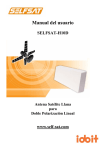
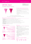
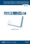
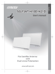
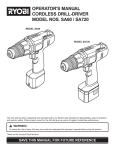
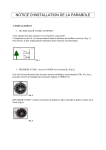
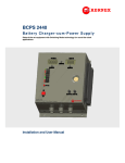
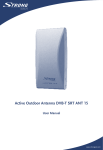
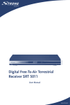
Picture similar
Satellite Antenna with integrated LNB
SlimSat SA60
User Manual
PART 1 • English
1.0 WHAT IS T SA60?
2
2.0 SAFETY INSTRUCTIONS
2
3.0 HOW TO INSTALL?
3.1 Step 1: Where to Install?
3.2 Step 2: Installation Choice
3.3 Step 3: Connecting the Antenna and the Set top box
3.4 Step 4: Pointing and locating the Signal (first without Attenuation Thin Pad)
3.5 Optimum Pointing & Finding the Signal (with Attenuation Thin Pad)
3
3
4
6
6
9
4.0 TROUBLESHOOTING CHECK LIST FOR INITIAL INSTALLATION
10
5.0 LOSS OF SIGNAL / RAIN FADE
10
6.0 INSTALLATION USING LONG CABLE
11
7.0 TECHNICAL SPECIFICATION
11
A.1 BOX CONTENT
12
English
TABLE OF CONTENTS
1
PART 1 • English
1.0 WHAT IS T SA60?
SlimSat SA60 is a Horn Array Type Satellite Antenna with Dual Linear Polarization,
it can receive signal from major Satellites and would replace a normal former 60cm Parabolic Dish.
Small, discreet and easy to use, it can be installed in a few minutes and used as a portable antenna for all
satellite receptions.
SlimSat SA60 can be used for both free to Air and encrypted (requiring a subscription with an operator)
channel reception; it can also receive all High Definition channels with a superior image quality.
For the use and installation, please read the following instructions and installation materials carefully.
2.0 SAFETY INSTRUCTIONS
n
n
n
n
n
n
n
n
n
n
n
n
n
n
n
Before using this product please read this manual carefully and follow exactly all installation,
mounting & orientation instructions.
All the instructions should be followed in order to avoid any technical problems.
Any electric or magnetic field close to the SlimSat SA60 may cause a bad reception or even cut
off the signal completely.
Do not drill the plastic cover of the antenna, which seals the antenna from moisture.
Handle the antenna with care as any impact will cause damage to the electronics.
Do not open the cover, any attempt to repair by a non-qualified person can be dangerous and
void the warranty.
Any obstacle (buildings, trees, etc....) will block the reception of the signal from the satellite to the antenna.
Do not paint or add any substance on the antenna cover, this will block the reception of the
signal from the satellite.
The cable between the antenna and the Satellite receiver should not exceed 30m as it will
decrease the quality of the signal.
The use non- isolated jacks will result in a loss of the signal level.
For an optimum signal reception please use the Attenuation Thin Pad for the first installation.
(for more details, please refer to chapter 3.5)
Do not forget to adjust the antenna and the bracket to the cross-polarity (skew angle please refer
to chapter 3.4 step 4).
Tighten all the screws of the antenna once you have finished the adjustments.
This product contains one universal LNB, it is forbidden to add, change or modify the LNB.
For more precise details on the above points or for any information, please ask your retailer or
customer service.
Warning!!!
Antennas improperly installed to an inadequate structure are very susceptible to wind damage.
This Damage can be very serious or even life threatening. The owner and installer assumes full
responsibility that the installation is structurally sound to support all loads (weight, wind & ice)
and properly sealed against leaks. The manufacturer will not accept liability for any damage
caused by a satellite system due to the many unknown variable applications.
2
PART 1 • English
By following the instructions step by step you can proceed easily to install SlimSat SA60 by yourself or
with the help of a professional antenna installer.
Before installing your antenna, you check that SlimSat SA60 box contains all the items listed above in the
‘Box Content’. In the event of any missing parts, please contact your distributor.
3.1 Step 1: Where to Install?
In order to receive a signal from the Satellite, SlimSat SA60 is to be installed in an open loop space
(outside the house or the apartment), in the direction of the satellite towards the equator, for which, you
will need a compass to exactly orient SlimSat SA60 toward the satellite (Note; please take reference to
the table of the Azimuth angles specified in the back pages of this manual)
Note:
To ensure an accurate compass reading, stay away from large metal
objects, specifically electrical cables and then make multiple readings
Make sure that there are no obstacles in front of SlimSat SA60 which can decrease
the signal reception quality, such as buildings, or trees (you may keep in mind that
trees will grow and may block the signal).
In order to be able to fix and install your antenna easily you might choose an easily
accessible place without any potential danger for installation.
Think about the way you might pass your cable in a discreet way from the SlimSat SA60 to your Set top
Box. The antenna should not be too distant from your satellite receiver; a cable longer than 30 meters can
decrease the quality of the signal.
Bad Quality Signal Reception
3
English
3.0 HOW TO INSTALL?
PART 1 • English
Good Quality Signal Reception
3.2 Step 2: Installation Choice
Depending on the choice of installation position for the SlimSat SA60, you can then decide on the
mounting type, all parts are included
A) Table Stand type
4
PART 1 • English
English
B) Wall Mounting Type
C) Clamp on Balcony Type
5
PART 1 • English
3.3 Step 3: Connecting the Antenna and the Set top box
Once you have installed the antenna in an open loop space and mounted the way you want it to be the
next step is to connect it all together.
In order to be able to watch your favourite satellite programs, you need to connect your satellite antenna
to a receiver by a cable.
The cable between the antenna and the Satellite receiver should not exceed 30m as it will decrease the
quality of the signal
The use of a long or bad quality cable and not isolated jacks can cause a loss of the signal level, it would be
preferable to use an RG6 Coaxial cable (HF 17VATC or 19VATC cable), in order to minimise a signal loss.
How to connect the cable to the antenna and the set top box?
It is important that the coaxial cable does not become damaged or kinked during the installation procedure.
3.4 Step 4: Pointing and locating the Signal (first without Attenuation Thin Pad)
Once all installed and connected, you can start
adjusting your antenna in order to receive a signal.
For that, you will need to move your antenna in
three different ways in order to receive the maximum
signal level & best reception quality. Whatever your
choice of mount type, you will be able to adjust your
antenna easily by following these instructions.
6
PART 1 • English
Note:
To adjust the antenna with precision and to allow a good reception (even in bad weather), professional
installers use a “signal meter”. This indicates the level of signal strength received. Only the use of this
measuring device guarantees an optimum adjustment.
English
A- Cross Polarisation (Skew Angle):
Obtain the Skew Angle of the chosen satellite, from the lists in this manual which cover many European
countries & big cities). Tilt your antenna to the specified degree by looking to the degree graduation
located on the back of the antenna bracket. Once achieved, tighten both screws connecting the Skew
Bracket (B1) to the Antenna Body (A1).
B- Elevation Angle:
Then obtain the Elevation angle according to the area location of the chosen satellite on the lists in
this manual. Then move your antenna up or down according to the angle, (you may use the graduated
surface of the bracket in order to make sure that you are on the right position. Once achieved, tighten
your elevation nuts on the Angle Bracket (B2), this is a preliminary adjustment which you may have to
fine tune later by using the pointing menu on the TV.
You may do a fine tuning for the elevation angle by following the peak signal level on your screen later on
once all three points have been followed.
7
PART 1 • English
C- Azimuth:
Finally obtain the area’s azimuth angle of the chosen satellite, on
the lists in this manual, Point the antenna in a generally southerly
direction, then, by using the compass rotate to the right or the left
towards south on your compass (180°).
All of the European satellites are located to the south, there will be a
minor difference in the azimuth angle from one satellite to another.
Once you have selected the chosen satellite on your receiver follow the
signal strength on the screen by fine tuning the azimuth and rotating
the antenna very slowly “to the right” or “to the left” in order to receive
the highest signal level from the satellite.
You should be able to find the satellite signal first and then the signal
peak, indicated on your screen. Once you sweep through the peak-signal point on the screen, mark the
position with a pencil and screw in your angle bracket to fix the antenna in this position.
The signal level and quality is indicated on the TV screen and will fluctuate and change colour according to the
adjustment & movement of the antenna while you are pointing & finding (azimuth, elevation and Skew angle).
The level indicates the power of the signal and the colour is the signal reception quality from the chosen satellite.
Once fine tuning is complete, and the signal is at its peak level with a good quality, you can stop
adjusting the antenna.
8
PART 1 • English
English
In order to watch Canal+ through ASTRA1(19.2 East) from the city ‘Brest’ of France, you will see Skew
angle at -19.7, Elevation angle at 30, and Azimuth angle at 149.6 (in reference to the angle table on the
back page of this manual)
< SKEW >
< Elevation >
< Azimuth >
3.5 Optimum Pointing & Finding the Signal (with Attenuation Thin Pad)
Use of Attenuation Thin Pad simulates bad weather conditions causing a signal loss and aids antenna
positioning to receive an optimum signal in all weather conditions.
Optimum pointing and finding to gain the best signal is only possible after passing through chapter 3.4 Step 4.
Please affix Attenuation Thin Pad back onto the face of antenna cover and you may start repeating to
make adjustment of Skew angle, Azimuth, and Elevation as done the same in chapter 3.4 Step 4, again to
achieve the maximum and optimum signal level.
Once completed, remove the Attenuation Thin Pad (keep pad in a safe place to use in future for portable
use) ensure that all the screws are well tightened to avoid the antenna moving position.
Note: During heavy cloud coverage or rainfall, the reception of signal level tends to weaken and in
some cases the signal level will not be possible by the use of Attenuation Thin Pad. So during
bad weather, you are recommended to skip step 6 for a use of Attenuation Thin Pad
Attenuation Filter
SLIMSAT
Keep this Filter for the First installation and Pointing
9
PART 1 • English
4.0 TROUBLESHOOTING CHECK LIST FOR INITIAL INSTALLATION
If the signal is not found, be sure the receiver user manual and the antenna user manual have been
followed closely, check the following:
n Make sure all cable connections are correct and each connection is seated / tightened properly.
n Inspect the inside of each cable connector for dirt or possible connector to case / shield short.
n Verify the Azimuth, Elevation and Tilt angles for your location by ZIP code.
n Make sure the Tilt and Elevation pointers are aligned correctly to the scales. Do not use washer
or bolt as reference.
n Make sure the Tilt adjustment is not changed from the recommended settings for the antenna location.
n Remove existing TV-specific components, such as TV splitter, etc; reduce the installation to the basic
connections called out in this guide. Such components may not work with the satellite signal and they may
be in the wall where you can’t see them. When in doubt, run RG6 cable directly to you receiver.
n Make sure there are no obstructions (trees, buildings, windows, corner or overhang of you roof,
your body or hands) – the signal does not pass leaves, branches, glass, etc.
n RG6 cable with solid copper center conductor is highly recommended because it has much lower
DC voltage drop compared to RG 6 cable with a copper-coated, steel center conductor.
n Standard RG 59 cable cases too much DC drop and signal drop; it can not be used to pass the
satellite signal. RG 6 coaxial cable must be used.
n Some after market, off-the-shelf add-on components may not be as advertised. They might
not work or could cause additional DC drops and signal amplitude attenuation. Remove such
components, go back to the basic connections called out in this manual and re-verify.
n Make sure the satellite cable is connected to the “SAT IN” jack, not the “ANTENNA IN” jack. The
“ANTENNA IN “ jack at the back of the receiver is for all off-air antenna input or cable TV input.
n If all are done correctly but the signal is still not found change the Elevation adjustment of the
antenna slightly (± 2°, then ± 4° from the called-for setting) and repeat the procedure.
n Make sure the Access Card from your receiver is fully inserted into the Access Card slot and
oriented correctly.
5.0 LOSS OF SIGNAL / RAIN FADE
n
n
n
n
10
The satellite signal may lost temporarily due to unusually heavy rainfall. An optimally alighted antenna,
along with the shortest possible cable run, minimizes the chances of “rain fade”.
Make sure the antenna is mounted securely to prevent it from being blown out of alignment in a
heavy wind.
Heavy snow accumulation on the antenna may reduce the satellite signal strength; snow should
be swept away as soon as possible.
Tree foliage growth into antenna’s line-of-sight to the satellite may result in gradual loss of picture.
English
PART 1 • English
6.0 INSTALLATION USING LONG CABLE
n
n
For installations where the RG 6 cables run from the receiver(s) to the LNB far exceeds 100 feet
(150 feet or more), as encountered in a commercial or multi-dwelling building, you need to use
an AC power booster module to bias the LNB.
You will also need an additional RF signal amplifier to compensate the signal amplitude loss.
Otherwise, your antenna and receiver may not work properly and be subject to frequent outages
in adverse weather. Contact a professional concerning such intallations.
7.0 TECHNICAL SPECIFICATION
Input Satellite Frequency:
Polarisation:
Antenna Gain:
Dimensions (W x H x D):
LNB:
LNB Output Frequency:
LNB voltage:
Operating Temperature:
Gross weight:
Net weight:
LNB voltage
Vertical
Horizontal
10.7 ~ 12.75 GHz
Dual Linear (Horizontal & Vertical)
33 dBi at 12.7 GHz
475 x 259 x 74 mm
Single LNB integrated
950 – 1,950 / 1,100-2,150 MHz
Vertical
11.5 ~ 14.0 /
-30 ~ +60 °C
5.3 kg
3.34 kg
Horizontal
16.0 ~ 19.0
11.5 ~ 14.0
16.0 ~ 19.0
11
PART 1 • English
A.1 BOX CONTENT
No
Symbol
1
A1
Antenna Body
1
2
P1
Attenuation PAD
1
3
B1
Skew Bracket
1
4
B2
Angle Bracket
1
5
B3
Main Support
1
6
B4
Window Bracket A
1
7
B5
Window Bracket B
1
12
Part name
Image
Quantity
8
B6
Fix Bracket A
1
9
B7
Fix Bracket B
1
10
B8
Spanner
1
11
C1
Compass
1
12
S1
Screw
M4x10 SEMS2
1
13
S2
Hex Bolt
M6x12 SEMS2
1
14
S3
Hex Bolt
M6x20 SEMS2
1
15
S4
Hex Bolt
M6x45 SEMS2
1
16
S5
Round Head Square
Neck Bolt M6x30
1
17
S6
Round Head Square
Neck Bolt M6x50
4
18
S7
Round Head Square
Neck Bolt M6x75
4
19
N1
Flanged Nut M6
8
20
E1
Rubber
4
13
English
PART 1 • English
A.2 APPENDIX 1
Great Britain
1
Germany
2
France
3
Italy
4
Spain
5
Switzerland
6
Norway
Denmark
7
Austria
8
9
10
Environmental Issues
ENVIRONMENTAL ISSUES
STRONG is committed to reducing the impact of its products on the environment.
To maximise the benefits of our design enhancements, your co-operation is required.
Electronic product recycling
Do not dispose of this product with your
domestic rubbish.
At the end of its useful life, this product
contains materials which when processed
correctly can be recovered and recycled. By
participating in the responsible recycling
of this product you will be reducing the
requirement for new raw materials and
reducing the amount of material that
would otherwise end up in landfill.
When you purchase a new, similar product
your retailer may offer to take this old one
off you. Alternatively, you can take it to
your local recycling centre. Your retailer or
local municipal authority will advise you of
the collection facilities available for waste
electronically products in your area. User
of this service will be free to you.
Within the scope of the European
legislation on Waste Electrical and
Electronic Equipment (Directive 2002/96/
EC valid as of August 2005) STRONG
provides a recycling system free of charge
for consumers to returning products after
end of life. For more information about
STRONG’s environmental policy to you:
www.strong.tv - select “About us” and
“Environmental Policy“ from
the submenu.
Packaging
When disposing of this
product packaging, please
ensure that it is recycled.
Packaging material is to be
depolluted in waste
separation.
Power Saving
To save power and money,
please put the product into
standby mode when not in
use. We also recommend
disconnection from mains
supply when not in use for longer
periods of time.
Batteries
Do not dispose of the batteries
from your handset with your
domestic waste.
Where they are available,
participate in your local municipal
or retailer collection schemes
for spent batteries. Batteries
discarded in landfill sites or
incinerated increases the chances
of pollutants being dispersed into
the atmosphere.
Alternations reserved 01/2008