1
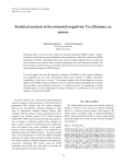
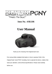
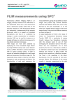
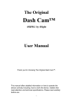
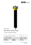
Design Report 2005
Intelligent Ground Vehicle Competition
Presented by Capra
Dynamic and Autonomous Robotic Club
École de technologie supérieure
Montréal, Canada
I certify that the engineering design in the vehicle (original or changes) by the current student
team has been significant and equivalent to what might be awarded credit in a senior design
course.
_________________________________
Tony Wong B.Ing., M.Ing. (ÉTS), Ph.D.
Director of Automated Production Engineering Department
École de technologie supérieure
Club Capra
Design Report
1.
École de technologie supérieure
Intelligent ground vehicle competition 2005
Introduction
Have you ever thought about a robot capable of thinking? Like a lot of people on this planet, the
Capra student club from the École de technologie supérieure started to dream about it a few years
ago. Mentis, from the Latin word “consciousness”, was born in the minds of a group of students
and was soon realized. Time has passed since the first version of Mentis came to life and now,
Mentis II is offering a solid base upon which to develop and test the results of the mobile
autonomous research done by the Capra’s team; the promotion of autonomous ground vehicles
being the main objective.
Mentis II is being presented at the 2005 IGVC for the last time since a completely new robot is
planned for the year 2006. The main changes from last year up to now include the addition of the
CANBus for various sensory devices on the robot, a better integration of those sensors on the
multimodal map, the use of Matrox Imaging Library (MIL) for the line detection as well as the
enhancement of the multimodal map by implementing an object cleaner, a timestamp generator
and a log book. This report presents the characteristics of Mentis II by focusing on these
improvements.
2.
Organization
The student club Capra integrates many disciplines for its benefit and for the benefit of its
members. Although the main design challenge is software, Mentis II also requires a crew capable
of handling electrical and mechanical design. Obviously, a strong administration team is present
to coordinate the developments. All the members of Capra are students voluntarily giving their
time to the project. Since the project is not related to any course in the university program, a
good organization is mandatory to achieving a certain level of performance. The team evolves
continuously as members arrive and leave throughout the year, making the integration of new
members even more difficult. The team also excelled at human resources management by
organizing weekly meetings for all sections in addition to a general meeting each month.
-1-
Club Capra
Design Report
École de technologie supérieure
Intelligent ground vehicle competition 2005
Capra is the only student club at the ÉTS developing an autonomous ground vehicle. In that
respect, the club represents the university at many events, the IGVC being the culminating point
of all the research carried out throughout the entire year. Here is a list of all the members
currently learning through and participating in the development of Mentis II.
François Coallier B.Sc., B.Ing., M.Sc.A.
IT and software engineering Dept. Director
Club Capra titular
Mathieu Goulet
Captain
Guillaume Lamontagne
Vice-captain
Charles Giard
Sponsors relations
Jean-Olivier Racine
Treasurer
Jean-Nicholas Lajoie
Mechanical team leader
Automated production engineering
Senior student
Charles Giard
Electric team leader
Electrical engineering
Senior student
Guillaume Leblanc
Automated production engineering
Senior student
Guillaume Lamontagne
Electrical engineering
Senior student
Léo Bardou-Marchand
Mechanical engineering
Freshman student
Zad Bouchedid
Mechanical engineering
Freshman student
Normand Langlois
Automated production engineering
Junior student
Philly Soan
Automated production engineering
Junior student
Mechanical Team
Frédéric Bisson
Electrical engineering
Freshman student
Claude Camiré
Electrical engineering
Freshman student
Jean-François Matte
Electrical engineering
Freshman student
Réginald Degraff
Electrical engineering
Senior student
Jean-Olivier Racine
Software team leader
Automated production engineering
Senior student
Pascal Mawrick
Software engineering
Senior student
Mathieu Goulet
Software engineering
Senior student
Yves Rioux
Software engineering
Senior student
Julien Godin-Viau
Software engineering
Freshman student
Pascal Beaudry
Software engineering
Freshman student
Elie Maalouf*
Electrical engineering
Master student
Jean-François Lassonde
Software engineering
Freshman student
Pierre-Yves Langlois*
Software engineering
Senior student
Simon Lessard*
Engineering
Phd student
Éric Cloutier
Automated production
engineering
Master student
Members followed by a (*) are currently inactive
Membres in italic were recruited this year
Electrical Team
Software Team
Figure 2-1 - Team organization
-2-
Club Capra
Design Report
3.
École de technologie supérieure
Intelligent ground vehicle competition 2005
Design Process
The design process of Capra is simple and relies on the usual scientific approach of engineering.
Since the members are all engineering students, acquiring a strong design process adds good
value to their course. The student club conducts most of its work through meetings and written
discussions on an online forum. Questioning newly discovered problems, new ideas and
reviewing designs is common. Also, good basic documentation is maintained by adhering to the
club’s documented objectives, project requirements and the actual user manual for the robot.
The first step of the design process is to identify the need. This need may consist of the rework of
an existing module, or the development of a new functionality. Once the need is identified, a
quick study of the feasibility and the resources cost is made in order to help establish priorities. It
is also important to study the actual schedule to decide whether or not to start the new project.
A new iteration commences once a project is well defined and if the schedule allows it. The use
of UML modelling for the software team or schematics for the electrical and the mechanical
teams is strongly encouraged, as it offers a powerful tool to help understand and review the
designed architecture. The development can start once a detailed design is completed. Aware of
its constantly changing member base, Capra has made the modifiability of Mentis a priority,
allowing for the quick and easy integration of new modules.
Before and after a project is integrated into the overall system, extensive unit and system testing
are performed in order to evaluate its functionality and to detect failures of any malfunctioning
parts. The already existing components are also tested to detect possible integration errors. This
year, Capra completely retested Mentis almost every two months.
4.
Design Innovations
Although Mentis II has been operational for a significant period of time, Capra spent the whole
year enhancing its performance and functionalities. Mechanically, the front has been modified to
-3-
Club Capra
Design Report
École de technologie supérieure
Intelligent ground vehicle competition 2005
reduce the time required for changing batteries and accessing the engines. A new range finder
support has been designed to allow vertical tweaking. The back wheels were exchanged to
improve performance on grass. Capra also decided to completely integrate the CANBus
technology to enhance communication between Mentis’ devices by making it more efficient and
reliable. From now onwards, CANBus will replace parallel and serial communication between
computers and input devices.
From the software point of view, Capra is really proud of Archie, a powerful library consisting of
a modular design which is easy to use, quick to understand and specialized in robotics. Archie
can be used within different contexts and on independent platforms. Moreover, Capra is about to
share Archie with other student clubs that are getting involved in autonomous robotics, and will
be used by future generations of Mentis. Finally, Capra acquired a new embedded Matrox 4
Sight II system. This computer is specialized in video acquisition and real time rendering. The 4
Sight is optimized to work with MIL.
5.
Functionalities
Since Capra is an unmanned robotic club, its main objective is the continuous development of
systems capable of achieving an autonomous navigation. Thus, as a guideline, this robot was
designed for three specific functionalities: IGVC’s Autonomous Challenge, its Navigation
Challenge and also the development of public relationships for the university.
5.1
Autonomous Challenge
The autonomous challenge consists of following lanes and avoiding obstacles. For this purpose,
the required input devices are the camera, the range finder and the encoders. While the range
finder scans the area for obstacles, the camera scans the land to detect lines and the encoder
reports the distance covered by the wheels. A software module processes the input data provided
by the camera in order to detect lines and subsequently reports it on the virtual map. Because
other patterns can interfere with the line detection algorithms, the vision modules also detect
-4-
Club Capra
Design Report
École de technologie supérieure
Intelligent ground vehicle competition 2005
speed bumps and sand traps to support navigation and line reports. On the other side, the range
finder module reports barrels and other physical obstacles on the virtual map. Since some fences
are beyond the range finder’s capacity, the vision system also helps to detect them by reading
different shape and color patterns. The encoder module reports the progress made by the robot on
the virtual map. With all this data, the navigation system is equipped with an expert system to
establish a trajectory, as explained in the software section of this design report.
Expert
Line Expert
Barrel Expert
Orientation Expert
Sooth Turn Expert
Task
Forbid line crossing and follow lines
Forbid physical obstacles crossing
Enforce going straight forward
Enforce smooth turns, avoid rough movements
Table 5-1 - Experts used for the Autonomous Challenge
5.2
Navigation Challenge
For the Navigation Challenge, the robot has to reach several navigation points on the map while
avoiding obstacles. The working base system for Mentis II is a bit different. In this challenge, the
range finder, the GPS and the encoders are important input devices. While the range finder
detects physical obstacles such as barrels or pot holes, the encoders report the progression of the
wheels and the GPS tries to detect any trajectory errors made by Mentis II. The vision system
attempts to detect physical obstacles such as high fences by recognizing recorded patterns. All of
the detected data is shown on the virtual map, and the navigation expert system constructs a
trajectory according to the implemented rules.
Expert
Navigation Expert
Barrel Expert
Sooth Turn Expert
Boundary Expert
Task
Enforce reaching waypoints coordinates
Forbid physical obstacles crossing
Enforce smooth turns, avoid rough movements
Forbid going out of bounds
Table 5-2 - Experts used for the Navigation Challenge
-5-
Club Capra
Design Report
5.3
École de technologie supérieure
Intelligent ground vehicle competition 2005
Public relationship
This year, a special effort has been put on public relationships as the sharing of knowledge is
very important in Capra. Throughout the year, Mentis II participated in several events to promote
the club as well as autonomous robotics in general. To arouse interest for robotics within
children, it is safe for them to individually take short rides on Mentis II while the remote control
is used to determine its movement. This remote control is also very useful for presentations and
transportation as it is safe and efficient.
6.
Non-functional requirements
6.1
Safety
Safety is a critical issue for any autonomous vehicle like Mentis II, especially since it is
presented relatively close to people. For this purpose, the remote control stop (E-Stop) is a
critical part of the robot that is implemented as a hardware shut down of the engines. Mentis II is
equipped with powerful motors to propel it on a variety of surfaces. However, the maximum
power is limited by the controller determining the maximum speed it can reach.
6.2
Reliability
Extensive testing was conducted on Mentis II for it to be more reliable. Some components have
been added to the motor drives as to protect them from high power surges. The software
architecture is a very reliable base upon which it is possible to implement new algorithms
without any worries of breakdown.
6.3
Durability
The materials used to build the mechanical structure of Mentis II are very solid materials such as
aluminium and carbon fiber. The cab and the structure underneath are strong enough to support
an individual’s weight without incurring any damage. The wires used to interconnect the
different devices within Mentis II are mostly clipped or soldered to prevent disconnection despite
the robot’s rapid movement.
-6-
Club Capra
Design Report
6.4
École de technologie supérieure
Intelligent ground vehicle competition 2005
Other requirements
In addition to the previous requirements, the club has to consider unstable human resources with
very different specialities and knowledge bases. Thus, modifiability, usability and testability are
three important aspects to consider throughout the entire project.
7.
Mechanical Design
Physically, Mentis II is almost an exact
replica of the robot used for last year’s
competition.
In
order
to
improve
its
mechanical capacities and steadiness, certain
components were replaced and adjusted.
Mentis II is powered by two 12 volts electric
wheel chair engines connected to their
Characteristics
Length
Width
Maximum height
Weight
Maximum inclination
Maximum speed
Positioning precision
Maximum capacity
original gearbox. During the past year, Capra
Value
120 cm
64 cm
91 cm
115 kg
21°
12.8 km/h (3.58 m/s)
± 6.5 cm
200 kg
Tableau 7-1 - Mentis II Technical Sheet
experienced some difficulties with the prototype when it was following a straight line trajectory.
To correct the problem, the original retention spring was replaced by a softer one more adapted
to the robot’s needs. Also, to ensure the functionality of the positioning system, the two drive
wheels’ optical encoders were exchanged for more efficient ones. These new devices allowed the
rotation speed of our motors to go up to 1500 RPM as opposed to 300 RPM. An aluminium
structure was installed on the platform to hold the cab in place and to assure the precise position
and stability of the camera stand. The use of an aluminium chassis allows for easier manipulation
of the fibreglass shell and simplifies the batteries maintenance operations. The frame was created
and assembled by members of the team using a TIG welding machine. Fixed to the aluminum
structure, the new camera stand is stable and minimizes vibrations produced upon movement of
the robot on the ground. To the stability of the camera stand, a simple installation system and a
specially designed head were added to allow adjustment of the camera position with four degrees
of freedom. On the robot’s front, the range finder was positioned on a rigid steel support
-7-
Club Capra
Design Report
École de technologie supérieure
Intelligent ground vehicle competition 2005
designed exclusively for a single position. The mechanical team is currently working on
replacing it with a multiple axis adjustable stand especially made for this range finder model.
This change will allow for the adjustment of this essential equipment to its best possible position.
8.
Electrical Design
8.1
Power Supply
The propulsion’s power supply comes from two serial batteries with a nominal voltage of 13
volts and can sustain the required 12 volts while supplying up to 36 amperes. This power is
processed via a motor drive based on a high speed, low ON resistance MOSFET bridge. With
four bridges placed in parallel, power consumption is considerably reduced. The MOSFET
control system uses a PIC microcontroller which supplies two precise PWM signals to drive the
bridge via a MOSFET driver. This control method makes Mentis II very power efficient. In fact,
most of the power is directly sent to the motors. Only a negligible part is absorbed by the
MOSFET at switching.
The electronic system power supply can come from two different sources: two serial batteries or
directly from a power outlet (120V AC). Two power supplies, one DC/DC and one AC/DC, is
then selected at will, dependent upon the active source and the current needs. This system
provides the ability to reduce battery usage when tests are performed on the electronic systems.
8.2
Control System
The control system is on a 486 DX2-66 DOS platform, which offers real time processing at very
low cost. The analog to digital and digital to analog conversion are done through a Sensoray IO
card on the ISA bus. Encoders, PWM control, motor speed, joystick inputs and drive current
feedback are all interfaces through this card. Laptop components are used to improve power
efficiency and resistance to shocks.
The intelligence system, the Matrox 4Sight, is an embedded computer with specialized hardware
that accelerates all computer vision tasks and offers high performance. Combined with the
-8-
Club Capra
Design Report
École de technologie supérieure
Intelligent ground vehicle competition 2005
Matrox Imaging Library (MIL), this Pentium Celeron 850MHz with 256 Mbytes of RAM and a
Meteor II Digital frame grabber is an excellent platform for our vision and artificial intelligence
needs.
8.3
Communication
The actual communication system is a mix of CANBus and standard serial communication
(RS232). Currently, only the compass and GPS are connected on the CANBus. A protocol was
designed to allow proper communication between the AI computer and the different modules.
This improvement offers provides the robot with a scalable, modular device architecture.
Capra - Electric division
Title: Electric Schematic
RF Emergency
Stop Button
System's Batteries
RF Joystick
Receiver
RF Link 1
RF Joystick
JS CHAN1
JS CHAN2
Joystick controller
+
Emergency controller
RF Emergency
Stop Receiver
RF Link 2
RF-EM RESET
Emergency LED
EM-STATE
12V
12V
24V
EM OUT
Emergency
Stop Button
Compas
-12V / +12V
Motors's Batteries
Range Finder
FireWire
Keyboard
Source
Select
AC/DC SW
AC/DC
Power
Supply
±5V, ±12V
Vision +
Intelligence PC
(4Sight)
±5V, ±12V
SVGA
12V
Mouse
24V
Motor
Drives
2
Fuses
Bloc
Control System
Power Bus
FireWire Camera
12V
DC/DC
Power
Supply
CAN BUS
24V
Half Brick DC/
DC Supply
DC/DC SW
Motors
ON/OFF
Circuit
+
Fuse
Bloc
Drives
Control
Motor
Drives
1
4Sight Power
Monitor
Switch Box
Embedded
LCD
Monitor
120 V AC
Power
Outlet
Floppy Drive
Keyboard 1
Control PC
CTRL Power
SVGA
Motors's
Batteries
Batteries
Selector
System's
Batteries
Encodeurs 1
Encodeurs 2
EM LED
Voltage
Monitor
EM-STATE
Motor 1
EM OUT
Motor2
Drives
Control
Acquisition Card
CTRL-PC RESET
CTRL-SW RESET
AUTONOMUS/JS
BRAKE ON/OFF
Encoder 1
Encodeurs 1
Encoder 2
Title
Projet
Date
Encodeurs 2
Auteur
Electric Distribution
Mentis 2
4 mai 2005
Révision
1.0
Charles Giard
Page 1
Figure 8-1 Mentis II Electrical Schema
-9-
Club Capra
Design Report
9.
École de technologie supérieure
Intelligent ground vehicle competition 2005
Software Design
The software section of Mentis II was designed with platform independence in mind. Of course,
certain aspects such as the controller cannot be disassociated from the drives or the motors, but
by building a flexible layered design, most of the developed software can be integrated into other
robots. The software design of Mentis II is divided into three logical parts, as explained below.
9.1
Archie
Archie is a software environment based on the implicit invocation architecture. Archie has the
responsibility to spawn, activate and connect independent modules. A XML file indicates which
module to spawn and activate, and allows data exchange between those modules. A text user
interface allows dynamic module activation as well. Archie also uses encapsulated data to
enforce coherence between modules in an ever-changing context.
A module is essentially a class or a set of classes that fulfill a limited set of requirements. This
high level of cohesion helps developers to understand the high level performance of the software,
which provides an excellent solution to a student club realm with rapidly changing human
resources. Each module implements an interface to ensure that they work in the current
environment. They consist of an activation control, a mechanism to read encapsulated data and
process it, in addition to an output method to send new encapsulated data to other connected
modules. Archie transmits encapsulated data between the corresponding modules.
This year, a logging feature has been added to Archie to help retrace and identify issues in the
software by indicating how the modules are reacting and communicating with their environment.
This feature is also used by the system to identify a malfunction and to react in a convenient
manner by avoiding errors, breakdowns or accidents.
As you can see, Archie does not implement functional requirements, but satisfies non-functional
requirements through its solidly implemented architecture.
- 10 -
Club Capra
Design Report
9.2
École de technologie supérieure
Intelligent ground vehicle competition 2005
Caasi
Caasi is the software implementing the functionalities of the prototype. It contains modules for
sensor management as well as the vision, navigation and cognitive mapping. It also provides a
graphic user interface along with a testing environment. In fact, Caasi is only a set of modules
developed especially for Mentis II functionalities with Archie in the backstage making it work.
Caasi is also the part of the software with the most changes from last year.
Sensor management is a very important task for Caasi. Mentis II’s sensors are composed of a
front camera, a range finder, a GPS, a compass and the encoders. All these physical devices are
sending data to the software in order to make the navigation system adjust to its environment.
For each device, a module links the external communication data with the inner message bus.
Some devices such as the camera and the range finder have their own set of devices to extract the
significant object from raw data, as explained later on in this section.
A brand new vision system was implemented this year. This vision uses the Matrox Image
Library which offers a wide variety of functionalities specialised in vision recognition systems,
camera recording and live image treatment. This year, the artificial vision has been improved
based on previous experience. Some team members worked for Matrox and were able to create a
partnership with the company in order to use MIL for our image treatment. The following
diagram explains the line detection process.
Figure 9-1 - Vision Detection Process
In addition to MIL, the team added some algorithms to improve resistance to environmental
changes such as brightness.
- 11 -
Club Capra
Design Report
École de technologie supérieure
Intelligent ground vehicle competition 2005
A navigation system was also implemented in Caasi. Its responsibility is to create a path vector
based on information kept in the virtual map, according to the rules implemented in the expert
system. First of all, a trajectory holder module keeps and monitors the trajectory length and
determines the good moment to add a new point in the vector. Then, the expert manager
constructs a set of potential points on a blackboard and sends it to the experts. Each expert uses
its rules with the knowledge found on the virtual map to vote on each candidate point. At this
point, an expert can vote against a candidate or vote in a scaled preference. Once every expert
has voted on the candidates, the expert manager compiles the vote, eliminates points that were
voted against and sums up the preferences on the other points. The winning candidate is then
added to the trajectory vector. The navigation system has been implemented with a full set of
configurations in the main XML file. Each expert and the trajectory holder can be adjusted with
a lot of details.
Another development of this year is a brand new virtual map which was implemented during a
major iteration of Caasi. This version divides the map into small zones. When a module needs a
list of object in a particular area, the virtual map only works with the relevant zones in order to
boost its efficiency. However, the insertion of new data is more complex because the map has to
run an algorithm to determine which zones may contains detected
objects. This solution was implemented because some performance
issues were noted last year when the map contained too many data. To
improve performance, a map cleaner was also added this year. This
module continuously scans the map to detect redundant or bad data. To
accomplish its task, the module tries to regroup objects with similar
coordinates and sizes and removes duplicate objects. Because the line
and barrel detection modules are constantly adding data even when it is
Figure 9-2 - Caasi's GUI
detecting the same objects over and over, adding a cleaner module became a priority.
- 12 -
Club Capra
Design Report
École de technologie supérieure
Intelligent ground vehicle competition 2005
Caasi also adds a graphic user interface, which greatly helps to understand the functioning of the
sensors and navigation system. From this interface, the developers can directly add objects into
Mentis’ virtual map, otherwise interact with the navigation system or just monitor the robot’s
thought process. In addition to the interface, Caasi possesses a complete testing environment to
help develop and understand the navigation system and the robot’s adherence to the desired
trajectory. The testing environment replicates the controller and imitates the reaction to the
trajectory usually sent by the navigation system.
9.3
The Controller
The controller is contained within the lower embedded system level of Mentis II and controls the
robot’s movements. It directly sends commands to the drives and receives raw data from the
acquisition card of the encoders on the wheel motors. The Controller is running on a DOS
environment and functions in two modes. The “joystick” mode takes data received from the
antennae and interprets it for movement. The “autonomous” mode receives the vector sent by
Caasi, smoothes it and transforms it in commands for the robot. It is the lowest level of
implementation for the robot.
10. Predicted performance and testing
Metric
Speed
Ramp climbing ability
Reaction time
Battery life
Distance at which
obstacles are detected
Dead ends, traps,
potholes
Accuracy of arrival at
navigation waypoints
Performance
8 km/h
21 degrees
500 ms to 2 s.
3 to 5 hours
10 m to 3 m
Detection of potholes and traps
with Caasi. Will take alternative
paths if encountering a dead end.
30 cm
Table 10-1 – Performances for Mentis II
- 13 -
Club Capra
Design Report
École de technologie supérieure
Intelligent ground vehicle competition 2005
11. Vehicle Costs
Items
Value
660,00 $
950,00 $
985,00 $
415,00 $
550,00 $
5.000,00 $
6.000,00 $
150,00 $
400,00 $
5.000,00 $
20.110,00 $
Frame
Electrical components
Communication devices
Motors, drives, encoders and wheels
Control embedded PC and IO card
Matrox 4Sight
SICK range finder
Camera Point Grey Research
GPS CMC Electronic
MIL
Total:
Paid cost
510,00 $
300,00 $
506,00 $
415,00 $
- $
- $
5.000,00 $
- $
- $
- $
6.731,00 $
Table 11-1 - Overall vehicle costs
12. Conclusion
In conclusion, Mentis II is Capra’s project to assist students developing autonomous robotics.
Although this prototype has been active for several years, the team is about to launch the
development of a new robot for IGVC 2006. The design will be quite different, based on our
experience with our current robot. More time will be dedicated to the design process, as it is the
most crucial part to success. The functionalities of the next generation are intended to be the
same as the current one, while its level of efficiency will hopefully rise dramatically.
- 14 -