1
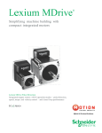
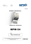
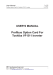
ADCO Controls Elevator Door Control User Manual ADCO User manual Elevator Door Control ADPMDC ADCO CONTROLS CONTACT: Tel/fax: +917925841070 Web: www.adcocontrols.com Email:[email protected] ADCO CONTROLS, PLOT-5318, PHASE-4, OPP. RAMOL POLICE CHOWKI, VATVA GIDC, AHMEDABAD-382445, GUJARAT (INDIA) 1 ADCO Controls Elevator Door Control User Manual Electrical Connection: Power Connection: Elevator Door Drive will operate on 220VAC +/-15 %, 50Hz or 60Hz with 1A Max Current from the Main Supply. There is Power Transformer between Drive and mains. So main supply will go to Power unit and Drive Supply will come from the power unit. There is plug and play connector between Drive and Power unit. Motor Connection: Just connect Motor Connector as per shown in drive, it is white 10 pin connector plug and play type without screw. This connector includes motor three phase supply as well as Encoder wire also. Control Inputs: +12V PH- PH+ COM 1 Door Open GND 2 DO 3 2 4 1 5 DC 6 2 7 1 8 Door Close 9 +12V 10 GND 1. Door Open and Door Close Connection: ADCO CONTROLS, PLOT-5318, PHASE-4, OPP. RAMOL POLICE CHOWKI, VATVA GIDC, AHMEDABAD-382445, GUJARAT (INDIA) 2 ADCO Controls Elevator Door Control User Manual 2. Photo Sensor Connection: Photo Sensor is used in almost all the Automatic Door Lift for the safety of the passengers. Drive has 12VDC, 1A output power for photo sensor so no Extra Power supply required for the photo sensor. DC DO 5 4 3 2 1 DO 1 DC 2 COM 3 COM 4 PH+ 5 PH+ GND 6 PH- 7 PH- 8 +12V 9 +12V 10 GND A : NPN Output Type Photo Sensor NPN Power Supply For Photo Sensor 9 8 7 6 +12V GND +12V 10 GND B : PNP Output Type Photo Sensor PNP Power Supply For Photo Sensor ADCO CONTROLS, PLOT-5318, PHASE-4, OPP. RAMOL POLICE CHOWKI, VATVA GIDC, AHMEDABAD-382445, GUJARAT (INDIA) 3 ADCO Controls Elevator Door Control User Manual 3 2 1 DO 4 DC 5 COM GND 6 PH+ 7 PH- 8 +12V 9 +12V 10 GND C : Relay Output Type Photo Sensor Power Supply For Photo Sensor Photo Sensor 1 2 Outputs: There are 4 relay output in Elevator Door Drive. Relay Contact have 5A/230VAC or 20A/24VDC. Drive gives information on the display as well as through relay like Door Fully Open, Door Fully Closed, Photo Sensor Detection and Obstruction Detection. Relay Output: 22 21 20 OBSTRUCTION RELAY 19 18 17 PHOTO RELAY 16 15 14 13 12 11 DCLIMIT RELAY DOLIMIT RELAY Fully Opened Fully Closed Photo Sensor Obstruction ADCO CONTROLS, PLOT-5318, PHASE-4, OPP. RAMOL POLICE CHOWKI, VATVA GIDC, AHMEDABAD-382445, GUJARAT (INDIA) 4 ADCO Controls Elevator Door Control User Manual Parameter List: No 0 1 2 3 4 5 6 7 8 9 A b C d E F O R L P T N J U Name Close Decelaration Opening Speed Closing Speed Open Slow Speed Close Slow Speed Open Slow Located Distance Close Slow Located Distance No of Input (1,2) Opening Side Selection Acceleration Time Deceleration Time Open Holding Force Close Holding Force Hold Release Time Safety Force Skate Speed Skate Distance Open Safety Force Max Current DispMode OpenSlowCurrentLimit CloseSlowCurrentLimit Pid_INC DLLPID1 Range 0-99 0-99 0-50 0-6 0-6 0-99 0-99 1 or 2 0-1 01-60 01-60 0-6 0-6 0-99 00-50 00-20 00-99 00-99 00-99 0-6 0-99 0-99 0-99 0-99 Factory Reset Value 8 50 40 1 1 25 25 1 0 20 6 2 2 25 30 4 10 30 55 4 25 15 2 10 ADCO CONTROLS, PLOT-5318, PHASE-4, OPP. RAMOL POLICE CHOWKI, VATVA GIDC, AHMEDABAD-382445, GUJARAT (INDIA) 5 ADCO Controls Elevator Door Control User Manual Parameter Explanation: 1. Open Speed: it is the speed at which the doors will be opened in there full speed range 2. Close Speed: it is the speed at which the door will be closed in there full speed range 3. Open Slow Speed: it is the speed at which the doors will be opened after their slow located distance 4. Close Slow Speed: it is the speed at which the doors will be closed after their slow located distance 5. Open Slow Located Distance: it is a distance from fully opened position 6. 7. 8. 9. A. B. C. from which the doors will open with the slow speed. As the value of this distance increase the doors will be open with slow speed earlier and as the value of this distance decreases the doors will open with slow speed later. Close Slow Located Distance: it is a distance from fully closed position from which the doors will close with the slow speed. As the value of this distance increase the doors will be close with slow speed earlier and as the value of this distance decreases the doors will close with slow speed later. No of Input: User can operate Either 2 or 1 input for the Door Open and Door Close. If 2 Input Selected both Door Open and Door Close input are activated for the operation. If 1 input selected only Door Open Input is activated, Door will open on Command On and Door Close when command off. Open Side Selection: During Setup First Door will open and DO LED will glow, in that condition if Door Close change Value in Open Side Selection parameter if 0 make 1 and if 1 make 0. Acceleration Time: This parameter varies the time of changing the doors speed from start to full speed which gives the smooth change over of the doors speed and prevents doors banging Deceleration Time: This parameter varies the time of changing the doors speed from full speed to slow speed which gives the smooth change over of the doors speed and prevents doors banging. Open Hold Force: After Fully open operation sometimes the doors slightly close due to the doors mechanism, to prevent this holding force is required to hold the doors in the closed position. This parameter decides the holding force to be applied to the doors after opening the doors. Close Hold Force: After Fully Close operation sometimes the doors slightly close due to the doors mechanism, to prevent this holding force is required to hold ADCO CONTROLS, PLOT-5318, PHASE-4, OPP. RAMOL POLICE CHOWKI, VATVA GIDC, AHMEDABAD-382445, GUJARAT (INDIA) 6 ADCO Controls Elevator Door Control User Manual D. E. F. O. the doors in the closed position. This parameter decides the holding force to be applied to the doors after Closing the doors Hold Release Time: During ideal condition holding is not required, like night or pick off time very less operation is there. During this time holding is not required, so after fully open or close if no other operation until hold release time, it will release hold force from the motor. Safety Force: it is the maximum force(closing Pressure) on any obstacle while closing the doors, if obstacle pressure is more then doors will be reopen and the obstruction relay-LED will be On. This feature prevents any accident in case of failure of safety sensor. Skate Speed: User can Vary Skate Speed using this parameter. Skate Distance: Up to Skate Distance Door will open slowly, so it will avoid the jerk, because up to skate only one door will there and after that landing door will come. Installation and Auto Tuning: Step1: Mount the Drive Unit, Power Supply Unit and Motor on the Door Header Properly. Step2: Connect Motor Cable to Drive unit properly. Step3: Connect Single Phase Supply with “EARTH” Properly to Power Supply unit. Step4: Connect Power Cable from Power Supply unit to Drive unit properly. Step5: Make Power On, Drive Display Will show “RDY”. Step6: Check all the Parameter as per Requirement, if any change required do the change as per requirement. Step7: Press Enter Button for 2 Sec. Screen show “P-00”. It will ask for Password. Enter 09 Default Passwords. Then it will show two modes “AUTO” and “PROG”. To enter in auto tuning mode press Enter button in “AUTO” mode. During Auto Tuning process “INIT LED” will blink and Door Open/Close Two Times and store the door data. During Auto tuning if “DO LED” on and Door is closing, change the Open Side Selection Parameter and Repeat the Procedure again. Step8: Connect the Control Input and Relay Output from the Main Elevator Control Panel or any Other Controlling Unit. Step9: Now it’s ready to Use, Enjoy Automatic Door. ADCO CONTROLS, PLOT-5318, PHASE-4, OPP. RAMOL POLICE CHOWKI, VATVA GIDC, AHMEDABAD-382445, GUJARAT (INDIA) 7 ADCO Controls Elevator Door Control User Manual Programming the Parameter: There are 3 keys and 4 Display on the top of drive unit. Using 3 keys and 4 display user can the change the parameter as per requirement. Press Enter Button for 2 Sec. Screen show “P-00”. It will ask for Password. Enter 09 Default Passwords. Then it will show two modes “AUTO” and “PROG”. To enter in Programming mode press Enter button in “PROG” mode. Using Enter key you can reach the parameter you want to change. Using the Up/Down Key user can change the parameter value. Press the ENTER key up to end of the parameter list, user will come out of the programming. ADCO CONTROLS, PLOT-5318, PHASE-4, OPP. RAMOL POLICE CHOWKI, VATVA GIDC, AHMEDABAD-382445, GUJARAT (INDIA) 8