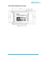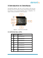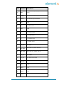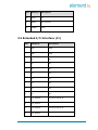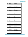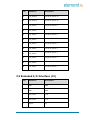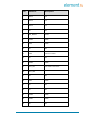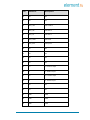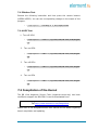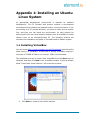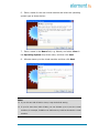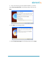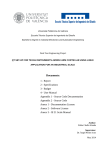
1
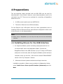
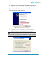
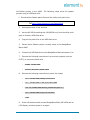
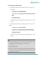
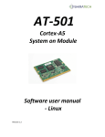
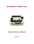
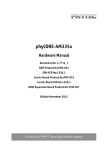
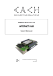
BB-View Cape
Portable LCD Solution for the BeagleBone Family
BY
User Manual
Version 3.0
Dated: 26th June 2014
DISCLAIMER
This product is intended to be used for ENGINEERING DEVELOPMENT,
DEMONSTRATION
OR
EVALUATION
PURPOSES
ONLY and is not
considered by element14 to be a finished end product fit for general consumer
use. Persons handling the product(s) must have electronics training and
observe good engineering practice standards.
The goods being provided are not intended to be complete in terms of required
design and/or manufacturing related protective considerations, including
product safety and environmental measures typically found in end products
that incorporate such semiconductor components or circuit boards.
Revision History:
Version
Date
Description
1.0
26/11/2013
Original Version
2.0
22/05/2014
Minor Updates
3.0
26/06/2014
Added support for Debian
Table of Contents
1 Product Overview .............................................................. 1
1.1 Brief Introduction ............................................................1
1.2 Kit Contents ....................................................................2
1.3 Board Interfaces ..............................................................2
1.4 System Block Diagram .....................................................2
1.5 Product Dimensions (mm) ................................................3
2 BB View Features .............................................................. 4
2.1 Hardware and Software Features:......................................4
2.2 Operational Parameters:...................................................4
3 Introduction to Interfaces ................................................. 5
3.1 LCD Interface (LCD).........................................................5
3.2 Extended I/O Interface (J1) ..............................................8
3.3 Extended I/O Interface (J2) ............................................ 10
3.4 Buttons ........................................................................ 13
3.5 LED Indicators............................................................... 13
4 Preparations .................................................................... 14
4.1 Installing Drivers for the USB Interface ............................ 14
4.2 Setting Up a Terminal Application .................................... 17
5 Demonstration and Compilation of Debian ...................... 19
5.1 Demonstration of Display Function ................................... 19
5.1.1 Image programming ................................................................ 19
5.1.2 Setting up Display Modes .......................................................... 21
5.1.3 Button Test ............................................................................. 22
5.1.4 LED Test ................................................................................. 22
5.2 Compilation of the Kernel ............................................... 23
6 Demonstration and Compilation of the TI SDK ................ 24
6.1 Demonstration of the Display Function ............................. 24
6.1.1 Image Programming on BeagleBone Black .................................. 24
6.1.2 Image Programming on BeagleBone ........................................... 25
6.1.3 Setting Up Display Modes – 4.3” ................................................ 25
6.1.4 Setting Up Display Modes – 7” ................................................... 26
6.1.5 Demonstration of Temperature Control ....................................... 27
6.1.6 Button Test ............................................................................. 28
6.1.7 LED Test ................................................................................. 29
6.2 Compilations of the TI SDK ............................................. 29
6.2.1 Building Development Environment ............................................ 29
6.2.2 Compiling Uboot ...................................................................... 30
6.2.3 Compiling Kernel ..................................................................... 32
6.3 System Update.............................................................. 33
7 Demonstration and Compilation of Angstrom .................. 35
7.1 Demonstration of Display Function ................................... 35
7.1.1 Image programming ................................................................ 35
7.1.2 Setting up Display Modes .......................................................... 37
7.1.3 Button Test ............................................................................. 38
7.1.4 LED Test ................................................................................. 38
7.2 Compilation of the Kernel ............................................... 38
Appendix 1: Installing an Ubuntu Linux System ................. 39
1.1 Installing VirtualBox ....................................................... 39
1.2 Installing an Ubuntu Linux System................................... 43
1 Product Overview
1.1 Brief Introduction
The BB-View is a portable LCD expansion cape with touchscreen capability
for BeagleBone boards, a credit-card-sized expandable Linux computer to
evaluate the TI’s Sitara™ AM335x ARM® Cortex™-A8 processors.
The BB-View is 24-bit LCD expansion cape supplied with an 18-bit TFT LCD
module, available in two size options: 4.3" & 7", which can display up to a
resolution of 480x272 (4.3" LCD) and 800x480 (7" LCD). Both have a 4-wire
resistive touchscreen interface.
BB-View has been designed with convenience in mind and extends the I/O
interfaces of the BeagleBone & BeagleBone Black allowing users to utilise a
touchscreen LCD module without sacrificing I/O interface access. BB-View
fits on top of the BeagleBone OR BeagleBone Black and still has full access to
all the GPIOs via two 46-pin connectors. It’s equipped with five switches
(four for GPIOs & one for Boot) and two user defined LEDs.
The BB-View draws power directly from the board (BeagleBone or BeagleBone Black)
eliminating the need for any kind of external power supply. The BB-View is
also supplied with a pre-compiled image with Linux QT demos to help set
up your BeagleBone & BeagleBone Black board quickly and easily.
Figure 1: LCD Connected to BeagleBone Black via BB View
Page | 1
1.2 Kit Contents
•
BB VIEW Expansion Board
•
4.3” LCD (optional)
•
7” LCD (optional)
1.3 Board Interfaces
Figure 2: BB View Interfaces
1.4 System Block Diagram
Figure 3: BB View System Block Diagram
Page | 2
1.5 Product Dimensions (mm)
Figure 4: BB View Dimensions
Page | 3
2 BB View Features
2.1 Hardware and Software Features:
A 24-bit compatible LCD expansion cape for the BeagleBone family
4-wire, 18-bit resistive touchscreen LCD modules:
o
4.3” LCD: 480x272 resolution
o
7” LCD: 800x480 resolution
Five switches (four for GPIOs &
Two user defined LEDs
Full access to all the GPIOs via two 46-pin connectors (besides those already
one for BOOT)
used by the BB-View)
Powered directly from BeagleBone boards, no external power supply
required.
Provided with pre-compiled BSP image with QT Demo to help setup the
BeagleBone board quickly and easily.
Works with BeagleBone & BeagleBone Black
Supporting TISDK and Angstrom image
Drivers and driver source code are provided along with BB-View
2.2 Operational Parameters:
Dimensions: 69.04mm x 54.61mm
Operating Humidity: 20% ~ 90%
Power Supply: +5V (provided by BeagleBone board)
PCB Layers: 4
Page | 4
3 Introduction to Interfaces
The BB-VIEW expansion cape has an LCD connector (LCD) and two
46-position dual-row connectors (J1 and J2) that are used as the extended
I/O interfaces of the connected BeagleBone Black or BeagleBone. This
chapter contains pin definitions for these connectors.
Figure 1-1
Components on BB VIEW
3.1 LCD Interface (LCD)
Pins
Definitions
Descriptions
1
B0
LCD Pixel data bit 23
2
B1
LCD Pixel data bit 20
3
B2
LCD Pixel data bit 17
4
B3
LCD Pixel data bit 11
5
B4
LCD Pixel data bit 12
6
B5
LCD Pixel data bit 13
7
B6
LCD Pixel data bit 14
Page | 5
Pins
Definitions
Descriptions
8
B7
LCD Pixel data bit 15
9
GND
GND
10
G0
LCD Pixel data bit 22
11
G1
LCD Pixel data bit 19
12
G2
LCD Pixel data bit 5
13
G3
LCD Pixel data bit 6
14
G4
LCD Pixel data bit 7
15
G5
LCD Pixel data bit 8
16
G6
LCD Pixel data bit 9
17
G7
LCD Pixel data bit 10
18
GND
GND
19
R0
LCD Pixel data bit 21
20
R1
LCD Pixel data bit 18
21
R2
LCD Pixel data bit 16
22
R3
LCD Pixel data bit 0
23
R4
LCD Pixel data bit 1
24
R5
LCD Pixel data bit 2
25
R6
LCD Pixel data bit 3
26
R7
LCD Pixel data bit 4
27
GND
GND
Page | 6
Pins
Definitions
Descriptions
28
DEN
29
HSYNC
LCD Horizontal Synchronization
30
VSYNC
LCD Vertical Synchronization
31
GND
GND
32
CLK
LCD Pixel Clock
33
GND
GND
34
X+
X+ Position Input
35
X-
X- Position Input
36
Y+
Y+ Position Input
37
Y-
Y- Position Input
38
SPI_CLK
SPI clock
39
SPI_MOSI
Slave data in, master data out
40
SPI_MISO
Slave data out, master data in
41
SPI_CS
SPI enable
42
IIC_CLK
IIC master serial clock
43
IIC_DAT
IIC serial bidirectional data
44
GND
GND
45
VDD1
3.3V
46
VDD2
3.3V
47
VDD3
5V
AC bias control (STN) or pixel data enable
(TFT)
Page | 7
Pins
Definitions
Descriptions
48
VDD4
5V
49
RESET
No connection
50
PWREN
GPIO
3.2 Extended I/O Interface (J1)
Pins
Definitions
Descriptions
1
GND
GND
2
GND
GND
3
NC
NC
4
NC
NC
5
NC
NC
6
NC
NC
7
NC
NC
8
NC
NC
9
NC
NC
10
NC
NC
11
LCD_DATA18
LCD Pixel data bit 18
12
LCD_DATA19
LCD Pixel data bit 19
13
LCD_DATA22
LCD Pixel data bit 22
14
LCD_DATA21
LCD Pixel data bit 21
Page | 8
Pins
Definitions
Descriptions
15
LCD_DATA16
LCD Pixel data bit 16
16
LCD_DATA17
LCD Pixel data bit 17
17
LCD_DATA20
LCD Pixel data bit 20
18
NC
NC
19
LCD_DATA23
LCD Pixel data bit 23
20
NC
NC
21
NC
NC
22
NC
NC
23
NC
NC
24
NC
NC
25
NC
NC
26
NC
NC
27
LCD_VSYNC
LCD Vertical Synchronization
28
LCD_PCLK
LCD Pixel Clock
29
LCD_HSYNC
LCD Horizontal Synchronization
30
LCD_DE
31
LCD_DATA14
LCD Pixel data bit 14
32
LCD_DATA15
LCD Pixel data bit 15
33
LCD_DATA13
LCD Pixel data bit13
34
LCD_DATA11
LCD Pixel data bit 11
AC bias control (STN) or pixel data
enable (TFT)
Page | 9
Pins
Definitions
Descriptions
35
LCD_DATA12
LCD Pixel data bit 12
36
LCD_DATA10
LCD Pixel data bit 10
37
LCD_DATA8
LCD Pixel data bit 8
38
LCD_DATA9
LCD Pixel data bit 9
39
LCD_DATA6
LCD Pixel data bit 6
40
LCD_DATA7
LCD Pixel data bit 7
41
LCD_DATA4
LCD Pixel data bit 4
42
LCD_DATA5
LCD Pixel data bit 5
43
LCD_DATA2
LCD Pixel data bit 2
44
LCD_DATA3
LCD Pixel data bit 3
45
LCD_DATA0
LCD Pixel data bit 0
46
LCD_DATA1
LCD Pixel data bit 1
3.3 Extended I/O Interface (J2)
Pins
Definitions
Descriptions
1
GND
GND
2
GND
GND
3
VDD_3V3B
3.3V
4
VDD_3V3B
3.3V
5
VDD5V
5V
Page | 10
Pins
Definitions
Descriptions
6
SYS5V
5V
7
SYS5V
5V
8
SYS5V
5V
9
NC
NC
10
SYS_RESETn
Reset
11
USER3
GPIO
12
LED0
GPIO
13
NC
NC
14
PWM
Power on enable
15
NC
NC
16
USER0
GPIO
17
I2C1_SCL
IIC master serial clock
18
I2C1_SDA
IIC serial bidirectional data
19
NC
NC
20
LED1
GPIO
21
NC
NC
22
NC
NC
23
USER2
GPIO
24
USER1
GPIO
25
NC
NC
Page | 11
Pins
Definitions
Descriptions
26
NC
NC
27
NC
NC
28
SPI1_CS0
SPI enable 0
29
SPI1_DO
SPI data 0
30
SPI1_D1
SPI data 1
31
SPI1_SCLK
SPI Clock
32
VDD_ADC
ADC power
33
NC
NC
34
NC
NC
35
NC
NC
36
NC
NC
37
Y+
Y+ Position Input
38
Y-
Y- Position Input
39
X+
X+ Position Input
40
X-
X- Position Input
41
NC
NC
42
NC
NC
43
GND
GND
44
GND
GND
45
GND
GND
Page | 12
Pins
Definitions
Descriptions
46
GND
GND
3.4 Buttons
Buttons
Definitions
Descriptions
1
USER0
Custom Button
2
USER1
Custom Button
3
USER2
Custom Button
4
USER3
Custom Button
5
BOOT
Select Boot Mode
3.5 LED Indicators
LEDs
Definitions
Descriptions
1
USER0
Custom LED indicator
2
USER1
Custom LED indicator
Page | 13
4 Preparations
The pre-compiled image provided with the BB VIEW can be used for
demonstration of the board. However, some demonstrations need to be
controlled via a PC. There are two methods for controlling a BeagleBone
board from a PC:
1.
A USB to serial module such as UART8000-U
2.
The built in Ethernet over USB functionality
For the Ethernet over USB option there are some preparations such as
installing USB over Ethernet drivers and software configuration which need
to be done prior to the demonstration.
NOTE:
When using a BeagleBone you can skip this step and use the USB debug
interface.
4.1 Installing Drivers for the USB Interface
1. An Angstrom/Debian system is already preprogrammed into the
on-board eMMC with of the BeagleBone Black. Connect the
BeagleBone Black to the USB interface of your PC using an OTG cable
and power on the board, after the Angstrom/Debian system startup is
complete, there you can find
will be a drive named “BEAGLEBONE”
shown in the “My Computer” window
2.
Windows will shortly detect the board and begin the driver
installation procedure. When a pop-up window is displayed as below,
select Install from a list or specific location (Advanced) and click
Next
Page | 14
Figure 5: Gadget Serial Driver Installation
3.
Click Browse in the following window and specify the location of the
CDCAM folder in the drive BEAGLEBONE and then click Next to install
the driver
NOTE
The drive letter shown below may change depending on your system
configuration
Figure 6: Driver Location
Page | 15
4.
Windows will shortly detect and begin the installation of the Ethernet
over USB functionality. Select Install from a list or specific location
(Advanced) and click Next again when on the following window shows
up to install the Ethernet over USB driver
Figure 7: Ethernet over USB Driver Installation
5. Click Browse in the following window to specify the location of
RNDIS folder in the drive BEAGLEBONE and then click Next
NOTE
The drive letter shown below may vary depending on your system configuration
Figure 8: Driver Location
Page | 16
4.2 Setting Up a Terminal Application
There are several terminal applications available however, we recommend
using PuTTY. PuTTY is a virtual terminal which can receive and display the
working information of the BB VIEW after entering the system. It needs to
be configured on your PC before it can communicate with the BB VIEW. The
following steps detail the configuration procedure.
1. Download the utility tools pack from:
www.element14.com/BeagleBone
2. Unzip the archive you downloaded (tools.zip) and subsequently unzip
the putty.zip archive contained within.
3.
Run putty.exe found within the uncompressed folder to open the
PuTTY Configuration window and configure it as shown below
Figure 9: PuTTY Configuration
Click Open once configuration is complete
Page | 17
4.
Enter the login credentials in the following window and press Enter
on your keyboard:
Note:
The default password for “root” on the TI SDK image is “temppwd”. On the
preinstalled Debian Image, “root” has no password
Figure 10: Login
After logging in successfully, a bash shell environment is activated. All the
shell instructions hereafter are typed and executed under this environment.
Page | 18
5 Demonstration and Compilation
of Debian
BB VIEW support has been added to the Debian operating system ready to
be run on the BeagleBone Black. This chapter will introduce how to carry out
demonstrations of the display function of the BeagleBone Black and BB
VIEW under Debian, as well as how to create a Linux development
environment and compile the system.
Figure 11: Debian on 4.3" LCD with BB-View
Note:
To avoid any confusion attributed to multi-line instructions, each instruction has
been preceded with a bullet point “”.
Please note that there are SPACES in the following instructions. Missing any
SPACE will lead to failure when running an application.
5.1 Demonstration of Display Function
5.1.1 Image programming
The preinstalled Debian image on the BeagleBone Black does not have
support for the BB VIEW.This can be easily remedied by simply patching the
Page | 19
old Debian system in the eMMC. The following steps show the update
process using a USB flash drive.
1. Download the Debian patch files and the utility tools pack from:
http://www.element14.com/BeagleBone
2.
Uncompress both of the archives
3.
Use the HP USB formatting tool (HPUSBFW.exe) from the utility tools
pack to format a USB flash drive
4.
Copy all the patch files to the USB flash drive
5.
Ensure that a Debian system currently exists in the BeagleBone
Black eMMC
6.
Connect the USB flash drive to the BeagleBone Black and power it on
7.
Execute the following instructions in a terminal program (such as
PuTTY) to mount the flash drive
8.
9.
$ mkdir /media/udisk
$ mount /dev/sda1 /media/udisk
Execute the following instructions to patch the image
$ cp -f /media/udisk/zImage /boot/uboot
$ cp -f /media/udisk/*.dtb /boot/uboot/dtbs
$ tar -xvf /media/udisk/kernel_modules.tar.gzvcd -C /
$ cp -f /media/udisk/xorg.conf /etc/X11/
$ sync
Power off the board and connect BeagleBone Black, BB VIEW and an
LCD display, and then power it on again
Page | 20
5.1.2 Setting up Display Modes
1. The following instructions are executed in PuTTY for the use of 4.3”
LCD displays
root@beaglebone:~# cd /boot/uboot/dtbs
root@beaglebone:~# cp am335x-boneblack-lcd4.dtb am335x-boneblac
k.dtb
root@beaglebone:~# sync
Now restart the board to complete the configuration for the 4.3” LCD
display.
2.
The following instructions are executed in putty for use of 7” LCD
displays
root@beaglebone:~# cd /boot/uboot/dtbs
root@beaglebone:~# cp am335x-boneblack-lcd7.dtb am335x-boneblack.dtb
root@beaglebone:~# sync
Now restart the board to finish the demonstration with a 7” LCD
display.
Note:
If you have calibrated the touch screen, after you change the display mode, you
must execute the following instructions to recalibrate in putty:
root@beaglebone:~# rm /etc/pointercal*
root@beaglebone:~# sync
and then reboot the board
The 4.3” and 7” LCD screens provided with the BB-View have different styles of
FPC. These are not cross compatible and using the wrong FPC will result in
apparent failure of the module
Page | 21
Figure 12: Calibration Screen
5.1.3 Button Test
Execute the following instruction and then press the custom buttons
(USER0-USER3). You can see corresponding changes in the output of the
program.
root@beaglebone:~# hexdump -C -v /dev/input/event2
5.1.4 LED Test
1. Turn off LED0
root@beaglebone:~# echo 0 >/sys/class/leds/bb-view\:led0/brightn
ess
2.
Turn on LED0
root@beaglebone:~# echo 1 > /sys/class/leds/bb-view\:led0/brightn
ess
3.
Turn off LED1
4.
33/sys/class/leds/bb-view\:led1/brightness
Turn on LED1
Page | 22
root@beaglebone:~# echo 1>
/sys/class/leds/bb-view\:led1/brightness
5.2 Compilation of the Kernel
The kernel source code is named bb-black-kernel-3.8.13-bb-view.tar.bz2
and has been modified to support the BB VIEW. It can be downloaded from:
http://www.element14.com/BeagleBone
Please refer to the BeagleBone Black User Manual for the details regarding
kernel compilation and updating.
Page | 23
6 Demonstration and Compilation
of the TI SDK
BB VIEW support has been built in to the TI SDK systems running on both
the BeagleBone and the BeagleBone Black. This chapter will introduce how
to carry out demonstrations of the display function of the BeagleBone Black
and BB VIEW using the TI SDK, as well as how to create a Linux
development environment and compile the system.
Note:
To avoid any confusion attributed to multi-line instructions, each instruction has
been preceded with a bullet point “”.
Please note that there are SPACES in the following instructions. Missing any
SPACE will lead to failure when running an application.
6.1 Demonstration of the Display Function
For the demonstration we will use a TI-SDK system image provided on the
element14 website. This requires programming the image into the
BeagleBone or BeagleBone Black first.
6.1.1 Image Programming on BeagleBone Black
1. Download the BB View TI-SDK Image File (ti-sdk-image.zip) and the
utility tools pack (tools.zip) from:
http://www.element14.com/BeagleBone
2.
Uncompress both of the archives
3.
Within the TI SDK zip (ti-sdk-image.zip) uncompress the image file
for either the BeagleBone or BaegleBone Black depending on your board
4.
Program the uncompressed image into a Micro SD card by using
Win32DiskImager.exe from the utility tools pack
Page | 24
5.
Insert the card into the BeagleBone Black, press and hold the Boot
button on the BB VIEW while powering on the board. Keep the button
held down until the bank of 4 LEDs light up for a few seconds
6.
When all 4 user LEDs stay constantly on, the image has been
programmed into BeagleBone Black. Please power off the board and
remove the Micro SD card, and then connect BeagleBone Black, BB VIEW
and a LCD display and power it on again
7.
Follow the instructions shown on the LCD to complete screen
calibration.
6.1.2 Image Programming on BeagleBone
1. Download the TI-SDK image (ti-sdk-image.zip) and the utility tools
pack (tools.zip) from:
http://www.element14.com/BeagleBone
2.
Uncompress both of the archives
3.
Within the TI SDK zip (ti-sdk-image.zip) uncompress the image file
for either the BeagleBone or BaegleBone Black depending on your board
4.
Program the uncompressed image into a Micro SD card by using
Win32DiskImager.exe from the utility tools pack
5.
Insert the card into the BeagleBone and connect the BeagleBone
Black, BB VIEW and an LCD display, and then power on the board to start
the system
6.1.3 Setting Up Display Modes – 4.3”
The procedure to set up display modes is the same on both the BeagleBone
and BeagleBone Black.
1. Connect to the BeagleBone board as shown in section 4
Page | 25
2. The following instructions are executed in the terminal window to
configure the BB View to use 4.3” LCD displays:
root@am335x-evm:~#
echo
"optargs=dispmode=4.3inch_LCD"
>
/media/mmcblk0p1/uEnv.txt
root@am335x-evm:~# sync
Note:
The system supports 4.3” LCD displays by default, and therefore there is no
need to execute these instructions if the default settings haven’t been changed.
3.
Restart the board to apply the settings, the BB View is now set up for
4.3” LCD displays.
6.1.4 Setting Up Display Modes – 7”
1. Connect to the BeagleBone board as shown in section 4
2.
The following instructions are executed for use of 7” LCD displays:
root@am335x-evm:~# echo "optargs=dispmode=7inch_LCD" > /medi
a/mmcblk0p1/uEnv.txt
3.
root@am335x-evm:~# sync
Now restart the board to apply the settings for 7” LCD displays.
Note:
If you have calibrated the touch screen, after you change the display mode, you
must execute the following instructions to recalibrate in putty:
root@am335x-evm:~#rm /media/mmcblk0p1/pointercal
root@am335x-evm:~# sync
And then reboot the board.
The 4.3” and 7” LCD screens provided with the BB-View have different styles of
FPC. These are not cross compatible and using the wrong FPC will result in
apparent failure of the module
Page | 26
6.1.5 Demonstration of Temperature Control
Temperature control is one of the typical applications included in the TI SDK
system. The following instructions show how to run this application.
1. Click Qt4 icon on the desktop of TI-SDK system as shown below
Figure 13: Run QT4
2.
Click Thermostat Demo in the following interface
Figure 14: Select Thermostat Demo
3.
Click the RUN button in the following interface
Page | 27
Figure 15: Run Thermostat Demo
4.
The interface of the temperature control application is shown below
Figure 16: Temperature Control Application
6.1.6 Button Test
Execute the following instruction in the terminal and then press the custom
buttons (USER0-USER3). You can see changes correspondingly in the
output of the program.
root@am335x-evm:~# hexdump -C -v /dev/input/event1
Page | 28
6.1.7 LED Test
Enter the following into the terminal:
1. Turn off LED0
2.
Turn on LED0
3.
root@am335x-evm:~# echo 1 > /sys/class/leds/LED0/brightness
Turn off LED1
4.
root@am335x-evm:~# echo 0 > /sys/class/leds/LED0/brightness
root@am335x-evm:~# echo 0 > /sys/class/leds/LED1/brightness
Turn on LED1
root@am335x-evm:~# echo 1 > /sys/class/leds/LED1/brightness
6.2 Compilations of the TI SDK
BeagleBone and BeagleBone Black share the same source code package for
the TI SDK system, and therefore the compilation and image updating
processes are the same for both boards.
6.2.1 Building Development Environment
Before getting started with system compilation, you must first build a Linux
development environment. (For installation of a Linux system, please refer
to 7Appendix 1:)
1. Download BB VIEW TI-SDK source code (ti-sdk-source.zip) from:
http://www.element14.com/BeagleBone
To the $HOME directory
2.
Execute the following instructions to install the development
environment:
$ cd $HOME
Page | 29
$./ti-sdk-am335x-evm-06.00.00.00-Linux-x86-Install --mode
console
3.
Follow the on screen prompts to finish the installation, the file
ti-sdk-am335x-evm-06.00.00.00 will now be in the $HOME directory.
4.
Execute the following command to install mkimage.
5.
$ sudo apt-get install uboot-mkimage
Execute the following instruction to define a temporary environment
variable for the compiler in the Ubuntu system
$ export PATH=$HOME/ti-sdk-am335x-evm-06.00.00.00/linux-devki
t/sysroots/i686-arago-linux/usr/bin/:$PATH
Note:
The instruction used to define environment variables can be added into .bashrc
in the $HOME directory so that the system can create the variable automatically
when booting up.
To view the path of the compiler, type echo $PATH into the terminal.
Now the development environment has been created successfully.
6.2.2 Compiling Uboot
The SDK provided officially by TI needs to be patched in order to support BB
VIEW. A Linux kernel has been patched and is available in the BB VIEW
TI-SDK source code (ti-sdk-source.zip) from:
http://www.element14.com/BeagleBone
It can be used as an alternative and compiled directly without need to apply
the patch. This section will introduce two uboot compilation processes.
Compiling uboot from TI
1. Copy u-boot-2013.01.01-psp06.00.00.00-bb-view.patch to
$HOME/ti-sdk-am335x-evm-06.00.00.00/board-support/
Page | 30
2. Execute the following instruction within the directory: board-support/
to apply the patch
$ cd ~/ti-sdk-am335x-evm-06.00.00.00/board-support/u-boot-2013
.01.01-psp06.00.00.00
3.
$ patch -p1 < ../u-boot-2013.01.01-psp06.00.00.00-bb-view.patch
Execute the following instruction to compile
cd $ ~/ti-sdk-am335x-evm-06.00.00.00/board-support/u-boot-2013
.01.01-psp06.00.00.00
$ make CROSS_COMPILE=arm-linux-gnueabihf- ARCH=arm distclean
$ rm -rf am335x
$ make O=am335x CROSS_COMPILE=arm-linux-gnueabihf- ARCH=ar
m am335x_evm
After the compilation is done, the files MLO and u-boot.img can be
found within am335x/ of the current directory.
Compiling uboot from element14
1. Execute the following command to uncompress the uboot source code
2.
$ cd ~/
$ tar xvf u-boot-2013.01.01-psp06.00.00.00-bb-view.tar.bz2
Execute the following instructions to compile
$ cd $HOME/ u-boot-2013.01.01-psp06.00.00.00
$ make CROSS_COMPILE=arm-linux-gnueabihf- ARCH=arm distclean
$ rm -rf am335x
Page | 31
$ make O=am335x CROSS_COMPILE=arm-linux-gnueabihfARCH=arm am335x_evm
After the compilation is done, the files MLO and u-boot.img can be
found within am335x/ of the current directory.
6.2.3 Compiling Kernel
The SDK provided officially by TI needs to be patched in order to support BB
VIEW. A Linux kernel has been patched and is available in the BB VIEW
TI-SDK source code (ti-sdk-source.zip) from:
http://www.element14.com/BeagleBone
It can be used as an alternative and compiled directly without need to apply
the patch. This section will introduce two kernel compilation processes.
Compiling kernel from TI
1. Copy linux-3.2.0-psp04.06.00.11-bb-view.patch from $HOME to
$HOME/ti-sdk-am335x-evm-06.00.00.00/board-support/
2. Execute the following instructions to install patch and then compile
the TI-SDK kernel
$ cd ~/ti-sdk-am335x-evm-06.00.00.00/board-support/linux-3.2.0psp04.06.00.11
$ patch –p0 < ../ linux-3.2.0-psp04.06.00.11-bb-view.patch
$ make ARCH=arm CROSS_COMPILE=arm-linux-gnueabihf- distclean
$ make ARCH=arm CROSS_COMPILE=arm-linux-gnueabihfam335x_evm_defconfig
$ make ARCH=arm CROSS_COMPILE=arm-linux-gnueabihf- uImage
modules
Page | 32
A kernel file with LCD support named uImage is generated under
arch/arm/boot/.
Compiling Kernel from element14
Execute the following instructions to unzip the source code and compile the
kernel image
$ cd ~/ti-sdk-am335x-evm-06.00.00.00/board-support/linux-3.2.0psp04.06.00.11
$ patch –p0 < ../ linux-3.2.0-psp04.06.00.11-bb-view.patch
$ make ARCH=arm CROSS_COMPILE=arm-linux-gnueabihf- distclean
$ make ARCH=arm CROSS_COMPILE=arm-linux-gnueabihfam335x_evm_defconfig
$ make ARCH=arm CROSS_COMPILE=arm-linux-gnueabihf- uImage
modules
A kernel file with LCD support named uImage is generated under
arch/arm/boot/.
6.3 System Update
Format a flash drive of a TF card to FAT32 and mount it under Ubuntu Linux
system, and then execute the following instructions to copy the image to the
flash drive of TF card (let’s assume the flash drive or TF card is mounted
under /mnt)
# cd ~
$ cp u-boot-2013.01.01-psp06.00.00.00/am335x/MLO /mnt
$ cp u-boot-2013.01.01-psp06.00.00.00/am335x/u-boot.img /mnt
$ cp linux-3.2.0-psp04.06.00.11/arch/arm/uImage /mnt
$ mkdir /mnt/rootfs
Page | 33
$ cd linux-3.2.0-psp04.06.00.11
$ make ARCH=arm CROSS_COMPILE=arm-linux-gnueabihfmodules_install INSTALL_MOD_PATH=/mnt/rootfs
$ cd /mnt/rootfs
$ tar -czvf ../kernel_modules.tar.gz ./
$ cd /mnt
$ rm –rf rootfs
$ ls
Connect the BB VIEW to a BeagleBone or BeagleBone Black and then
connect the power supply. To update the image, insert the flash drive into
the board and execute the following instructions after entering the TI SDK
system. (If a TF card is used instead of a flash drive, please change the path
in the instructions accordingly)
$ cp /media/sda1/MLO /media/mmcblk0p1/
$ cp /media/sda1/u-boot.img /media/mmcblk0p1/
$ cp /media/sda1/uImage /media/mmcblk0p1/
$ tar -xvf /media/sda1/kernel_modules.tar.gz -C /
$ sync
$ reboot
Page | 34
7 Demonstration and Compilation
of Angstrom
BB VIEW support has been added to the Angstrom operating system ready
to be run on the BeagleBone Black. This chapter will introduce how to carry
out demonstrations of the display function of the BeagleBone Black and BB
VIEW under Angstrom, as well as how to create a Linux development
environment and compile the system.
Note:
To avoid any confusion attributed to multi-line instructions, each instruction has
been preceded with a bullet point “”.
Please note that there are SPACES in the following instructions. Missing any
SPACE will lead to failure when running an application.
7.1 Demonstration of Display Function
7.1.1 Image programming
The preinstalled Angstrom image on some BeagleBone boards does not
have support for the BB VIEW. This can be easily remedied by simply
patching the old Angstrom system in the eMMC. The following steps show
the update process using a USB flash drive.
1. Download the BB View Angstrom Patch files and the utility tools pack
from:
http://www.element14.com/BeagleBone
2.
Uncompress both of the archives
3.
Use the HP USB formatting tool (HPUSBFW.exe) from the utility tools
pack to format a USB flash drive
4.
Copy all the patch files to the USB flash drive
Page | 35
5.
Make sure that an Angstrom system currently exists in the
BeagleBone Black eMMC
6.
Connect the USB flash drive to the BeagleBone Black and power it on
7.
Execute the following instructions in a terminal program (such as
PuTTY) to mount the USB flash drive
8.
$ mkdir /media/udisk
$ mount /dev/sda1 /media/udisk
Execute the following instructions to patch the image and then
restart the system
$ cp -f /media/udisk/uImage /boot/
$ cp -f /media/udisk/*.dtb /boot/
$ tar -xvf /media/udisk/kernel_modules.tar.gz -C /
$ opkg install /media/udisk/xf86-input-tslib_0.0.6-r17.1_armv7a-vf
p-neon.ipk
9.
$ cp /media/udisk/50-tslib.conf /usr/share/X11/xorg.conf.d/
$ sync
Modify the display width by entering the Angstrom system, and then
modifying the DefaultDepth value of /etc/X11/xorg.conf
DefaultDepth 16
To
DefaultDepth 24
10. Power off the board and connect the BeagleBone Black, BB VIEW and
an LCD display, and then power it on again
Page | 36
7.1.2 Setting up Display Modes
The following instructions are executed in PuTTY for the use of 4.3” LCD
displays:
root@beaglebone:~# cd /boot
root@beaglebone:~# cp am335x-boneblack-lcd4.dtb am335x-boneblac
k.dtb
root@beaglebone:~# sync
Now restart the board to complete the configuration for the 4.3” LCD
display.
The following instructions are executed in PuTTY for use of 7” LCD displays
root@beaglebone:~# cd /boot
root@beaglebone:~# cp am335x-boneblack-lcd7.dtb am335x-boneblac
k.dtb
root@beaglebone:~# sync
Now restart the board to complete the configuration for the 7” LCD
display.
Note:
If you have calibrated the touch screen, after you change the display mode, you
must execute the following instructions to recalibrate in putty:
root@beaglebone:~# rm /etc/pointercal*
root@beaglebone:~# sync
and then reboot the board
The 4.3” and 7” LCD screens provided with the BB-View have different styles of
FPC. These are not cross compatible and using the wrong FPC will result in
apparent failure of the module
Page | 37
7.1.3 Button Test
Execute the following instruction and then press the custom buttons
(USER0-USER3). You can see corresponding changes in the output of the
program.
root@beaglebone:~# hexdump -C -v /dev/input/event2
7.1.4 LED Test
1. Turn off LED0
root@beaglebone:~# echo 0 > /sys/class/leds/bb-view\:led0/brightn
ess
2.
Turn on LED0
root@beaglebone:~# echo 1 > /sys/class/leds/bb-view\:led0/brightn
ess
3.
Turn off LED1
root@beaglebone:~# echo 0 > /sys/class/leds/bb-view\:led1/brightn
ess
4.
Turn on LED1
root@beaglebone:~# echo 1 > /sys/class/leds/bb-view\:led1/brightn
ess
7.2 Compilation of the Kernel
The BB View Angstrom Source Code (angstrom-source.zip) has been
modified to support the BB VIEW. It can be downloaded from:
http://www.element14.com/BeagleBone
Please refer to the BeagleBone Black User Manual for the details regarding
kernel compilation and updating.
Page | 38
Appendix 1: Installing an Ubuntu
Linux System
An appropriate
development
environment
is
required
for
software
development. The CD included with product contains a development
environment which needs to be installed under a Linux environment. If you
are working on a PC running Windows, you have to create a Linux system
first, and then you can install the environment. An easy method for
achieving this is to use virtual machine software such as VirtualBox to install
Ubuntu Linux on an emulated/virtual PC. The following sections will
introduce the installation processes of VirtualBox and an Ubuntu system.
1.1 Installing VirtualBox
You can access http://www.virtualbox.org/wiki/Downloads to download the
latest version of VirtualBox. At the time of writing VirtualBox requires a
minimum of 512MB of RAM to run however 1GB is recommended.
The installation process is simple. Start VirtualBox from the Start menu of
Windows, and then click New in the VirtualBox window. A pop-up window
titled “Create New Virtual Machine” will be shown as below:
5.
Click Next to create a new virtual machine.
Page | 39
6.
Enter a name for the new virtual machine and select the operating
system type as shown below:
7.
Enter a name in the Name field, e.g. Ubuntu, and select Linux in
the Operating System drop-down menu, and then click next.
8.
Allocate memory to the virtual machine and then click Next
Note:
If your PC has 1GB of RAM or lower, keep the default setting
If your PC more than 1GB of RAM, you can allocate up to 1/4 to the virtual
machine, for example, 512MB out of 2GB memory could be allocated to virtual
machine.
Page | 40
9.
If this is the first time you have installed VirtualBox, you need to
select Create new hard disk in the following window, and then click
Next
10. Click Next in the following window
11. Select Fixed-size storage in the following window and click Next
Page | 41
12. Define where the hard disk data is stored and the default space of
the virtual disk (8GB at least), and then click Next
13. Click Finish in the following window
14. Your PC will then create a new virtual disk
Page | 42
15. A window with summary of the newly created virtual machine will be
shown as below when the creation process is done. Please click Finish to
complete the whole process.
1.2 Installing an Ubuntu Linux System
After VirtualBox is installed, we can install the Ubuntu Linux system. Visit
http://www.Ubuntu.com/download/Ubuntu/download to download the ISO
image file of Ubuntu, and then follow the steps below:
1. Start VirtualBox from the Start menu and click Settings on the
VirtualBox window. A Settings window will be shown as below
Page | 43
2.
Select Storage on the left in the Settings window and click the CD
icon next to the option Empty under IDC controller in the right part of
the window, and then find the ISO file you downloaded
3.
Select the ISO file you downloaded and click OK as shown below
Page | 44
4.
Click Start on the VirtualBox window, the Ubuntu installation
program will start as shown below:
5.
Some prompt windows will pop up during the initiation process. You
just need only click OK all the way to the end of the process.
6.
Click Install Ubuntu to start installation when the following window
appears
Page | 45
7.
Click Forward to continue the process
8.
Select Erase disk and install Ubuntu and click Forward
Page | 46
Note:
Selecting this option will only affect the virtual hard drive you created earlier
and will not lead to any content loss on your hard drive.
9.
Click Install Now in the following window to start installation:
10. Some simple questions need to be answered during the installation
process. Please enter appropriate information and click “Forward”. The
following window is the last question that will appear during the process:
Page | 47
11. After all the required information is properly
properly entered in to the fields,
select Log in automatically and click forward.
12. The installation of Ubuntu may take between 15 minutes to an hour
depending on your PC’s specification. A prompt window will be shown as
below after installation is done. Please select Restart Now to restart
Ubuntu system.
13. The Ubuntu system is ready for use after restarting. Normally
Normally the
ISO file shown below will be ejected automatically by VirtualBox after
restarting Ubuntu. If it is not, you can eject the ISO file manually in the
Settings window of VirtualBox. The following window shows the settings
window after the ISO file is ejected.
Page | 48
Page | 49