1
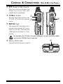
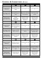
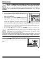
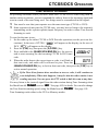
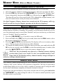
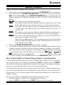
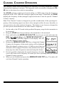
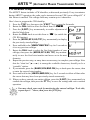
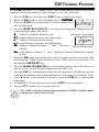
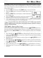
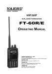
CONTROL & CONNECTIONS
(TOP & FRONT PANEL)
c Antenna Jack
Connect the supplied rubber flex antenna (or another
antenna presenting a 50-Ohm impedance) here.
d MIC/SP Jack
This four-conductor miniature jack provides connection points for microphone audio, earphone audio, PTT,
and ground.
Do not allow the VX-6E to become submerged in water while the plastic
cover over the MIC/SP jack is removed.
c de f
e VOL Knob
This control adjusts the audio volume level. Clockwise rotation increases the volume
level.
f DIAL Knob
This (inner) 20-position detented rotary switch is used for setting the operating frequency, and also is used for menu selections and other adjustments.
g LCD (Liquid Crystal Display)
The display shows current operating conditions, as indicated on the next page.
h POWER Switch
Press and hold in this switch for one second to
toggle the transceiver’s power on and off.
i Keypad
These 18 keys select many of most important operating features on the VX-6E.
The functions of the keys are described
in detail on the pages to follow.
g
h
j Microphone
The internal microphone is located here.
k Speaker
i
j
k
l
The internal speaker is located here.
l TX/BUSY Indicator Lamp
This indicator glows green when the squelch opens, and turns red during transmit.
During “Emergency Channel” operation (see page 62), this indicator will glow (or
flash) white. Also, this indicator can be useful as a flashlight in a dark environment
via Set Mode Item 34: LED LT; see page 96 for details.
VX-6E OPERATING MANUAL
3