1
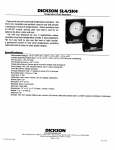
IV-4M User Manual 1 FCC Notice This equipment has been tested and found to comply with the limits for a field disturbance sensor, pursuant to Part 15 of the FCC Rules. The user is cautioned that changes or modification not expressly approved by C & K Systems could void the users authority to operate this equipment. Note: This equipment has been tested and found to comply with the limits for a Class B digital device, pursuant to Part 15 of the FCC Rules. The limits are designed to provide reasonable protection against harmful interference in a residential installation. This equipment generates, uses and can radiate radio frequency energy and, if not installed and used in accordance with the instructions, may cause harmful interference to radio communications. However, there is no guarantee that interference will not occur in a particular installation. If this equipment does cause harmful interference to radio or television reception, which can be determined by turning the equipment off and on, the user is encourage to try to correct the interference by one or more of the following measures: - Reorient or relocate the receiving antenna. - Increase the separation between the equipment and receiver. - Connect the equipment into an outlet on a circuit different from that to which the receiver is connected. - Consult the dealer or an experienced radio/TV technician for help. Industry Canada Notice This digital apparatus does not exceed the Class B limits for radio noise emissions from digital apparatus as set out in the Radio Interference Regulations of the Canadian Department of Communications. Le present appareil numerque német pas de bruits radioelectriques dépassant les limites applicables aux appareils numérique de Classe B prescrites dans le règlement sur le brouillage Radioelectrique Edicte par le Ministère des Communications du Canada. 2 Contents Product Features Safety Notice Terminology Function Buttons Sound Types Inputs and Outputs Installation System Operation System Programming System Programming Status System Operating Status Frequently Asked Questions and Answers Troubleshooting Product Specifications ○ ○ ○ ○ ○ ○ ○ ○ ○ ○ ○ ○ ○ ○ ○ ○ ○ ○ ○ ○ ○ ○ ○ ○ ○ ○ ○ ○ ○ ○ ○ ○ ○ ○ ○ ○ ○ ○ ○ ○ ○ ○ ○ ○ ○ ○ ○ ○ ○ ○ ○ ○ ○ ○ ○ ○ ○ ○ ○ ○ ○ ○ ○ ○ ○ ○ ○ ○ ○ ○ ○ ○ ○ ○ ○ ○ ○ ○ ○ ○ ○ ○ ○ ○ ○ ○ ○ ○ ○ ○ ○ ○ ○ ○ ○ ○ ○ ○ ○ ○ ○ ○ ○ ○ ○ ○ ○ ○ ○ ○ ○ ○ ○ ○ ○ ○ ○ ○ ○ ○ ○ ○ ○ ○ ○ ○ ○ ○ ○ ○ ○ ○ ○ ○ ○ ○ ○ ○ ○ ○ ○ ○ ○ ○ ○ ○ ○ ○ ○ ○ ○ ○ ○ ○ ○ ○ ○ ○ ○ ○ ○ ○ ○ ○ ○ ○ ○ ○ ○ ○ ○ ○ ○ ○ ○ ○ ○ ○ ○ ○ ○ ○ ○ ○ ○ ○ ○ ○ ○ ○ ○ ○ ○ ○ ○ ○ ○ ○ ○ ○ ○ ○ ○ ○ ○ ○ ○ ○ ○ ○ ○ ○ ○ ○ ○ ○ ○ ○ ○ ○ ○ ○ ○ ○ ○ ○ ○ ○ ○ ○ ○ ○ ○ ○ ○ ○ ○ ○ ○ ○ ○ ○ ○ ○ ○ ○ ○ ○ ○ ○ ○ ○ ○ ○ ○ ○ ○ ○ ○ ○ ○ 3 ○ ○ ○ ○ ○ ○ ○ ○ ○ ○ ○ ○ ○ ○ ○ ○ ○ ○ ○ ○ ○ ○ ○ ○ ○ ○ ○ ○ ○ ○ ○ ○ ○ ○ ○ ○ ○ ○ ○ ○ ○ ○ ○ ○ ○ ○ ○ ○ ○ ○ ○ ○ ○ ○ ○ ○ ○ ○ ○ ○ ○ ○ ○ ○ ○ ○ ○ ○ ○ ○ ○ ○ ○ ○ ○ ○ ○ ○ ○ ○ ○ ○ ○ ○ ○ ○ ○ ○ ○ ○ ○ ○ ○ ○ ○ ○ ○ ○ ○ ○ ○ ○ ○ ○ ○ ○ ○ ○ ○ ○ ○ ○ ○ ○ ○ ○ ○ ○ ○ ○ ○ ○ ○ ○ ○ ○ ○ ○ ○ ○ ○ ○ ○ ○ ○ ○ 4 4 7 8 9 9 12 13 14 20 21 22 24 25 The IntelliVision IV-4M is a 4-channel Thin Film Transistor Liquid Crystal Display Video Monitor. The IV-4M has Automatic Sequential switching with programmable channel selection, alarm enabling and channel Dwell Time. Any combination of Black & White and Color cameras can be connected to the system. Sensor-Alarm Detection and Video Loss Detection are provided for added security. Product Features Automatic Sequential Switching camera images are displayed on the monitor according to programmed channel selection and Dwell Times. Manual Switching The selected-channel camera image is displayed on the monitor. Video Signal Loss Detection A flashing video channel LED and a pulsing audible alarm is activated if there is a loss of video on any of the programmed channels. Safety Notice The system should be unplugged from the wall and disconnected from the camera cables during electrical storms and during extended periods of disuse to protect the unit from damage due to electrical discharge or power surges. 4 Automatic Alarm Channel Monitoring The display switches to the camera corresponding to the channel alarm input. Video Monitor Output An auxiliary output allows connection to a Video Cassette Recorder or external monitor. User Programmability Channel selection, Dwell Time and alarm input enable are user programmable. The Dwell Time can be set to any value from two to 30 seconds. The Dwell Time is the length of time the camera image will be displayed on the monitor before the monitor switches to the next programmed camera when in sequential mode. An alarm input can be connected to any of the four input channels and enabled or disabled. System Memory Protection The programmed settings are stored in an ElectricallyErasable Programmable Read-Only Memory (EEPROM) and are saved when power is turned off. 5 External Alarm Output An output is provided for triggering an external device when the monitor receives an alarm. The open-collector alarm output shorts to ground (goes low) for 30 seconds when triggered. The audible alarm sounds for 20 seconds. Automatic Alarm Reset Options There are two options for automatic alarm reset after the completion of the alarm period: Option A The system returns to sequential mode after the alarm period. The Alarm channel LED flashes until the ALM RESET button is pushed. Option B The system will only display alarmed channels until ALM RESET is pressed. Master Arm/Disarm This feature allows the user to enable or disable the Alarm Inputs by pressing the ALM RESET/SEQ button and the PROG button at the same time. 6 Terminology Sequential Mode Camera images are displayed in programmed sequence. Sequential mode is overridden when the monitor goes into Alarm mode. Manual Mode Camera image is selected manually by pressing the selected channel button and sequential mode is stopped. Video Loss There is no video signal from one or more cameras. Sensor Alarm Dry contact inputs from external sensors. A 2k Ohm End-of-Line (EOL) resistor is required at the sensor. Normally Closed (NC) contacts are wired in series with the EOL resistor. Normally Open (NO) contacts are wired in parallel across the EOL resistors. 7 Function Buttons ON/OFF The button must be held down for two seconds to turn the unit ON. A momentary push turns the unit OFF. PROG Activates Programming mode when held down for two seconds. Switches between channel, Alarm, and Dwell Time programming modes. Exits from programming mode when held down for two seconds. 8 ALM RESET/SEQ Activates Sequential mode. Resets sensor alarm and alarm memory. Resets the Video Loss audible alarm. ALM RESET/SEQ and PROG Simultaneously pressing these two buttons toggles the Master Arm/Disarm function. Channel Selection Switches into Manual mode. Selects channel to be programmed, sensor alarm enable or Dwell Time setting in program mode. Disables sequential mode. Sound Types Steady Sensor alarm is detected. Pulsating Video loss is detected. Inputs and Outputs Power Input 12VDC 1 Amp. Sensor Alarm Input Terminal Block Four external sensor inputs associated with the four camera channels. 9 Alarm Output Alarm output terminal provided for external devices. Video Output 75-Ohm BNC coaxial video output connector for use with an external video monitor. Video Input Four BNC connectors for camera cables, terminated in 75 Ohms. Tint Adjusts the video image hue. Color Adjusts the video image color saturation. Contrast Adjusts the video image dark to light contrast. Brightness Adjusts the video image brightness. 10 Typical Application 11 Installation 1 Connect DC power to the unit and switch the power ON only after all connections have been made. A 12VDC/1A AC to DC adapter is required. 2 Connect the 75-Ohm coaxial cable from the camera video output to the appropriate channel input. Up to four cameras may be connected to the unit. 3 Connect the external alarm outputs to the alarm input terminals on the terminal block. Up to four alarm inputs may be connected to the unit. 4 Connect the Alarm Out terminal to the VCR or external alarm device. 5 Connect a 75-Ohm coaxial cable from the Monitor output to the external video monitor or VCR. 12 System Operation Activate Sequential Switching Press the ALM RESET/SEQ switch. ALM RESET/ SEQ LED will light. Activate Manual Mode Press Channel button for the camera you want to see. The system stops sequencing through the rest of the cameras. ALM RESET/SEQ LED will extinguish. Activate Program Mode Press the PROG button and hold it down for two seconds. Exit Program Mode Press the PROG button down and hold it for two seconds. The unit will automatically drop out of programming after 30 seconds of no button activity. Clear Alarm Memory Press the ALM RESET/SEQ button. Entering and exiting Program Mode will also reset the alarm memory. Master Arm/Disarm Press the ALM RESET/SEQ button and PROG buttons simultaneously to enable or disable the Alarm inputs. When Master Arm is selected, the ALM LED will be lit. 13 System Programming The following features can be programmed in the IV-4M: • • • • Sequential switching sequence channels. Enable/Disable alarm input for each channel. Camera Dwell Time for each channel. Enable/Disable automatic alarm reset. In programming mode, the PROG button is used to step through the four programming functions listed above. 14 Selecting Camera Channel for Sequential Display 1 Press the PROG button for two seconds and release it to put the system into program mode. • • • The PROG LED will light. The SEQ LED will be lit. LEDs of all selected channels will be lit. 2 Press the button of the channel you want to select. • • The Channel LED will light. The selected channel is now in the sequence. 3 To remove a channel from the sequence, press the button of a selected channel. • The channel LED will go out when the channel button is pushed. 4 Press the PROG button and hold for two seconds to exit program mode. 15 Enabling or Disabling Alarm Input for a Video Channel 1 Press the PROG button for two seconds and release it to put the system into program mode. • • • The PROG LED will light. The SEQ LED will be lit. LEDs of all selected channels will be lit. 2 Press the PROG button again. • The ALM LED will light. 3 Press the channel button that you want to enable or disable. • The channel LED will light if you are enabling the alarm for the channel or extinguish if you are disabling the alarm for that channel. 4 Press and hold the PROG button down for two seconds to exit program mode. 16 Setting the Dwell Time for a Video Channel In Dwell Time Programming, the PROG button is used to advance through the four channels in numerical sequence. This allows the Channel buttons to be used to input the Dwell Time for the currently selected channel. Observe the monitor to determine which channel is currently selected for programming. 1 Press the PROG button for two seconds and release it to put the system into program mode. • • • The PROG LED will light. The SEQ LED will be lit. LEDs of all selected channels will be lit. 2 Press the PROG button twice again to advance through the channel selection and alarm enable programming functions. • • The DWELL TIME LED will light. Channel 1 Dwell Time is initially selected for programming. 17 • The Channel buttons add Dwell Times to the selected channel as follows up to 30 seconds: - Chan 1 = 2 sec Chan 2 = 4 sec Chan 3 = 8 sec Chan 4 = 16 sec For example, if the Channel 1 and Channel 3 LEDs are lit, the Dwell Time is ten seconds (2sec+8sec). 3 Press the Channel button(s) corresponding to the desired Dwell Time. 4 Press the PROG button to display the next channel to be programmed for Dwell Time. The channels advance in numerical sequence when the PROG button is pressed. 5 Press and hold the PROG button down for two seconds to exit program mode. 18 Enabling or Disabling Automatic Alarm Reset 1 Press the PROG button for two seconds and release it to put the system into program mode. • • The PROG LED will light. The SEQ LED will be lit. 2 Press the PROG button six times to advance through the other programming functions. • All four channel LEDs will be off to indicate Automatic Alarm Reset programming is selected. 3 Press the ALM RESET/SEQ button to toggle between Option A or Option B. (See page 6.) • The DWELL TIME/ALM SEQ LED will flash for Option A. The DWELL TIME/ ALM SEQ LED will be OFF for Option B. 4 Press the PROG button for two seconds to exit program mode. 19 System Programming Status LED DWELL TIME/ ALM ALM SEQ ALM RESET/ PROG SEQ Status 1 2 3 4 l m m l m m l l Channel Selection Programming is selected. Channels 1 & 4 are selected in sequential mode. m l l m m l m l Alarm Enable Programming is selected. Sensor inputs 2 & 3 are enabled. l m m m l m m l Dwell Time Programming is selected. Dwell Time of two seconds is selected m m m m Y m m l Automatic Alarm Reset Programming is selected. Option A is selected. Table Legend: m = Steady Off. System mode, Channel, Dwell Time is deselected. l = Steady On. System mode, Channel, Dwell Time is selected. Y = Flashing. Video Loss, Alarm is detected. 20 System Operating Status LED 1 2 3 4 l m m m DWELL TIME/ ALM ALM SEQ m m ALM RESET/ PROG SEQ l Status m Sequential Mode is selected. Channel 1 is being monitored. Sequential Mode is selected. Sensor 4 is in alarm, and Channel 4 is being monitored. m m m l m Y m m m m m l m l m m Y m Y l m m m m Table Legend: m Home Mode is selected. Channel 4 is being monitored. Master Arm is enabled. Video loss is detected on channels 1 & 3. Channel 4 is being monitored. = Steady Off. System mode, Channel, Dwell Time is deselected. l = Steady On. System mode, Channel, Dwell Time is selected. Y = Flashing. Video Loss, Alarm is detected. 21 Frequently Asked Questions and Answers 1 What happens when sensor alarms are detected? • • • • • The system switches to the alarm channel instantly. The Alarm piezo sounds for 20 seconds. The Alarm LED flashes and the Sequential LED goes out. After 20 seconds, the Alarm Piezo will turn off. The Alarm LED will continue flashing. In a multiple alarm situation, the IV-4M will switch between the alarmed channels with a Dwell Time of four seconds. If Automatic Alarm Reset Option A is programmed (see page 6), the system returns to normal sequential mode 30 seconds after the last sensor alarm. The Alarm LED and alarmed channel LED(s) will continue to flash. 22 2 How do you reset the alarm sounder and clear alarm memory? • Press the ALM RESET/SEQ button. The alarm sounder will stop and the Alarm LED will stop flashing. The ALM RESET/SEQ LED will turn on, and the monitor will go into sequential mode. 3 What happens when video loss is detected? • • • The channel LED for the channel that has lost video will flash. The Alarm Piezo will pulse for 20 seconds. Pressing the ALM RESET/SEQ button will silence the Alarm piezo, but the videoloss channel LED will continue to flash until the video is restored or the channel is deselected in programming mode. Video-loss channels will be displayed on the monitor with a dwell time of two seconds. 23 Troubleshooting Problem Possible Cause Solution Power LED is not lit. The power adapter is not plugged into the unit or the wall. Make sure the adapter is plugged in. Power is on but there is no video on the monitor. The camera is not programmed, or the correct channel is not selected. Make sure that the camera channel is programmed on the monitor and that the channel is selected on the monitor. There is a beeping audible alarm. There is no video signal on one or more channels in the programmed sequence. Make sure that the cable is connected to the correct channel and that there is power to the camera. There is a steady audible alarm. There is a sensor alarm. If the sensor alarm is invalid, check that the EOL resistor is connected properly. (See illustration on page 11.) The VCR cannot record the video from the monitor. There is no video from the unit, or the VCR is not correctly setup. Make sure that the VCR is connected to the Monitor Out 75-Ohm BNC connector. Make sure that the VCR is in RECORD mode. Make sure that the Record tab is on the tape cassette. 24 Product Specifications IV-4M (NTSC and PAL models) Display Type TFT (Active Matrix) Color LCD Display Format (pixels) Number of Video Inputs 600 (H) x 234 (V) 4 (BNC connector) Video Input Signal 1Vp-p composite video, color or B/W Number of Video Outputs 1 for monitoring or VCR (BNC connector) Video Output Signal 1Vp-p composite video Gain Bandwidth Unity (1:1) 20 MHz (-3dB) S/N Ratio 55 dB typical Cross Talk Dwell Time -45 dB typical 2 to 30 seconds, programmable in 2-second increments Number of Alarm Inputs 4 Alarm Input Connection Screw terminal block, 2k Ohms EOL resistor configuration Number of Alarm Outputs 1 25 Alarm Output Type Screw terminal block, open collector, sink 50 mA max., normally open Alarm Indications Built-in alarm buzzer, flashing alarm LED System Mode Operation Home, Sequential, and Program 12 +/- 1.5 VDC + 9W, 12VDC (750 mA) Input Voltage Power Input Connection Power Consumption Storage Temperature Operating Temperature Humidity Dimensions Weight Power Supply -25 C to 60 C (-13 F to 140 F) -10 C to 50 C (14 F to 122 F) 95% Relative Humidity or less non-condensing 215 mm W x 160 mm D x 130 mm H (8 1/2 W x 6 1/4 D x 5 1/4 H) 0.9 Kg (2 lbs.) Included 26 27 C & K is a registered trademark of C & K Components, Inc. IntelliVision is a registered trademark of C & K Systems, Inc. Copyright 1998 C & K Systems, Inc. P/N 5-051-586-00 Rev A http://www.cksys.com 28