1
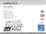
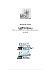
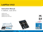
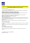
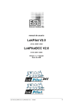
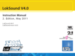
user manual
LokPilot
Item.No.61600
user manual Version 1.0
April 2005
user manual LokPilot mfx (61600) V1.0 04/2005
1
General Features:
The LokPilot mfx is specifically designed for use with
Märklin® central units: it can be operated with the
known central units such as Delta or control unit
6020 resp. 6021, but also with the new Märklin®
systems command stations working with the mfxdata format. Of course it can also be operated with
conventional AC. The LokPilot mfx automatically
detects the required operating mode. It can control
DC motors, coreless motors (e.g. Faulhaber) or universal motors with HAMO-magnets.
Due to its unique features LokPilot mfx offers you
flexibility and reliability that you have come to expect
from a digital decoder. Due to its flash-technology it
can be updated at any time.
• Multi-protocol operation Motorola / mfx
•Suitable for analogue AC layouts
• Fully automatic change to all 3 operating modes
„on-the-fly“ (AC analogue, mfx digital, Motorola
digital)
• 4th generation load control: adjustable with 3 CVs
to the motor characteristics
• Smooth and silent tact frequency of 40 kHz
• Supports Märklin® brake sector
• 128 speed steps in mfx-mode, 14 speed steps in
Motorola®-mode
• Maximum current of decoder: 1.2 Amperes
• Dimensions: 22.5 x 15.5 x 4.5 mm
• Future proof: Firmware upgrades due to FlashMemory possible
Important note:
• The LokPilot mfx is designed for use with model
railways only
• Avoid mechanical force and impact on the
decoder
• Do not expose to wet and humid conditions
• Do not remove the heat shrink sleeve around
the decoder
• Never solder on the circuit board, extend cables
if necessary
• Never wrap the decoder in insulation tape, since
this may prevent heat diffusion and cause
overheating
• Always disconnect the circuit when installing the
decoder
• Make sure that no blank wire ends come into
contact with any metal parts of the locomotive
• Make sure that no wires are squeezed or cut by
the model’s transmission parts when
reassembling the locomotive.
• 100% compatible to Märklin® systems
• Supports the directional control bit when changing from analogue to digital
•Permanent storage of speed and status of all
functions
• Comfortable modification of settings: the engine
does not have to be opened
• 2 directional light outputs with ca. 180 mA each,
over-current protected
• 2 freely available function outputs (F1 and F2),
with ca .180 mA each, over-current protected
• Maximum current of all 4 outputs: ca. 350 mA
• Shunting speed can be switched with F3
• Acceleration and deceleration can be switched off
with F4
• Freely selectable speed curve (*)
• All outputs can be assigned to outputs as desired (*)
Prior to installation
The locomotive must be in perfect technical condition
prior to installation. Only a locomotive with a troublefree mechanism and smooth running properties in
analogue mode should be converted for digital mode.
Stift
1
2
3
4
5
6
7
8
Description
colour
motor connections right
back up light
function F1
track connection 1
motor connections
light front
common (+pole )
track connection 2
Orange
yellow
green
black
grey
withe
blue
red
1 = orange
• Lighting effects: Strobe, Double strobe, Mars- und
Gyro light, firebox, Zoom. Brightness of each
output can be separately dimmed.
• Motor output: maximum 1.1 A, over-current
protected
2
5 = grey
Fig.1: Interface as per NEM650/652
user manual LokPilot mfx (61600) V1.0 04/2005
green
violett
F1
F2
yellow
withe
light
back
light
front
LokPilot
blau
black
red
orange
grey
engine
Fig.2: Wiring of LokPilot with isolated funktions
green
violett
F1
F2
yellow
withe
light
back
Light
front
LokPilot
Lokgehäuse
orange
schwarz
rot
grey
engine
Fig.3: Wiring of LokPilot with common pole connected to the chassis
Wear and tear parts, such as motor brushes, wheel
contacts, light bulbs, etc. must be inspected and
cleaned or replaced if necessary.
All work has to be carried out with the locomotive
placed on a suitable base (not the track) and
definitely un-powered. Make sure there can never
be any electrical power applied to the loco during
the conversion – even inadvertently.
Locomotives with NEM Interface
The LokPilot mfx is equipped with an interface as per
NEM 650/652 (NMRA page 9.1/9.2 - see fig. 1). Installation in locomotives with interface is therefore
particularly easy:
user manual LokPilot mfx (61600) V1.0 04/2005
• Remove the body from the chassis. Please refer
to the instructions provided with your
locomotive!
• Remove the plug or the analogue directional
relay from the interface socket. Please keep
it for later use.
• Insert the plug in such a way that pin 1 ofthe
plug (near the red / orange wires) is located
next to the point marked *, +, . or 1. Please
take care to avoid bending the pins. Do not
rely on the assumption that the wires
have to lead from the socket in a
certain direction: only the position
of pin 1 determines which way the
plug has to be inserted.
3
• Locate the decoder at a suitable position within
Connecting Auxiliary Functions
the locomotive. Most modern models have
sufficient space for a decoder. Use double sided
adhesive tape or a small amount of hot glue.
Any load may be connected to the light and
function outputs as long as it doesn’t exceed the
maximum current. Please note that the overload
protection of the decoder responds very quickly
and will switch off all functions immediately in case
of overload or short circuit.
Locomotives without interface
First separate all wires in the locomotive and make
sure there is no hidden connection from one of the
motor terminals to the chassis or the wheel contacts.
The motor terminals definitely must be insulated.
Fleischmann models often have such a connection,
which can easily be overlooked. Check all connections
using an Ohmmeter and make sure there are no
short circuits between the motor terminals and the
wheel contacts.
How to proceed depends on how the headlights and
auxiliary functions are wired:
a) If directional headlights and functions are isolated
from the locomotive body proceed as per figure 2.
b) Directional headlights and functions may be
connected with their common to the track voltage
(e.g. almost all Märklin® -locomotives and older
Fleischmann or ROCO locomotives are wired like
that) as per figure 3.
• Connect the red wire to the right rail pickup (or
centre pick up in AC models)
• the black wire to the left rail pickup (wheels in AC
models).
Therefore use only 16 V bulbs or higher and a
maximum nominal current of 50 mA:
Incandescent lamps have a high starting current
and this may activate the overload protection
of the decoder when the lights are switched on.
Use only digital smoke generators (e.g. Seuthe No.
11) for locomotives whose light and function
outputs are connected as shown in figure 2. All
other smoke generators may draw too much
current. Some commercially available smoke
generators have a higher nominal current than 250
mA!
In locomotives connected as shown in figure 3 an
analogue smoke generator e.g. Seuthe No. 10 is
required.
Make sure that the total current for all function
outputs does not exceed the permitted current
rating and avoid short circuits between outputs.
Although outputs of LokPilot mfx decoders are
protected, high voltage on the terminals or a
short circuit may damage the decoder!
• Connect the orange wire with the motor terminal,
which was previously wired to the right wheel pick
up (centre pick
up in AC models).
Set-up and initial operation
• The grey wire goes to the terminal, which was
originally connected to the left rail (common rails
for AC models).
Before replacing the body and reconnecting the
engine it is recommended to carry out a function
test.
• Solder the back-up lights to the yellow wire, the
front headlights to the white wire.
The factory pre-set Motorola address is 03.
• Connect the green wire to the function output,
which you want to switch with function button
F1.
•Connect the purple wire with the function output,
which you want to switch with the function button
F2.
If your locomotive is wired as per b) above, then
wiring is completed.
The decoder must „report“ automatically
to mfx central units.
• Does the locomotive move in either direction?
• Turn the lights on: are they operating correctly? If
the LokPilot mfx V2.0 decoder is used in a
locomotive with NEM interface: check if the NEM
connector is plugged in correctly.
In the case as per fig. 2 you have to connect the
second pole of all light bulbs or other loads to the
blue wire. The blue wire must not be connected to
the chassis!
4
user manual LokPilot mfx (61600) V1.0 04/2005
Motorola-Mode
The LokPilot can be operated with all previously or
currently available Märklin® devices reps. with
compatible systems. The functions F1 to F4 can only
be used with the so called „New Motorola®-format“.
Inn order to active this you must set the DIP-switches
1 and 2 of the 6021 in the upper position („On“).
blinking)
•Then you can change other registers in the same
manner
•To exit the programming mode select register „80“
or turn off the track voltage for a moment (press
„Stop“-button on 6021, then „Go“-button)
mfx-mode
With Märklin® mobile station
The LokPilot mfx is automatically detected by all
central units compatible to Märklin® systems such
as mobile station or central station. After registration
of the decoder it can be operated immediately.
With the Märklin® mobile station it is child’s play to
enter the name of the engine, the maximum speed as
well as acceleration and deceleration. Even a decoder
reset is easily possible. Other parameters cannot be
activated with the mobile station.
Adjusting decoder parameters
The LokPilot mfx supports many parameters.
Depending on the type of central unit it may not be
possible to modify all parameters.
With Märklin® 6020 / 6021
In conjunction with all previous Märklin® central units
6020 resp. 6021 the most important parameters are
available. They are sorted in CVs as listed in table 1. In
order to adjust these CVs proceed as follows:
(The throttle must be set to 0.
No other engines may be on the layout.
Take note of the blinking lights of the engine!)
• Press the „Stop“- and „Go“-buttons of the 6021
at the same time (simultaneously), until a Reset is
triggered. (Alternately pull the mains plug and reinsert afterwards)
• Press the „Stop“-button in order to turn off the
track voltage
• Enter the current decoder address (alternative:
„80“)
• Activate change of direction with the throttle (turn
the knob left beyond the „Stop“-position until you
hear a click), hold the knob there and press the
„Go“-button
• The LokPilot mfx is now in programming mode
(headlights are blinking)
• Enter the number of the parameter (CV) you want
to change (two digits).
• Confirm by pressing „change of direction“ (now
the headlights blink in double mode)
• Enter the new value for the register (two digits)
•Confirm by pressing „change of direction“
(headlights are on for 1 second and then start
user manual LokPilot mfx (61600) V1.0 04/2005
With Märklin® central station or ESU LokProgrammer
The LokPilot mfx has a large number of adjustable
parameters. They can be adjusted comfortably with
the aid of a graphic display either with the central
station or the ESU LokProgrammer 53450. Besides
the parameters described above the following
parameters are also available:
• Freely selectable speed curve
• Parameters for load control
• Function mapping: you determine which function
button triggers which function and which symbol
is displayed.
• Assigning lighting effects to the various function
outputs: The LokSound mfx decoder offers a large
choice of lighting effects such as dimming, flash,
blinking or simulating the firebox. You determine
which output operates with which effect and how
bright the lamps should be.
• Selection and settings of parameters in analogue
modes resp. brake sectors
• Setting of maximum speed in analogue mode
• Various other settings
Tips und Tricks
Adjusting Load control
The load control of the LokPilot mfx can be adapted
to different types of motors. The standard settings
match most motors very well but may have to be
adjusted for other models. This is particularly true for
coreless motors (Faulhaber, Maxxon) where we
recommend setting the K-value (CV 54) to a lower
value.
5
Decoder-Reset
You can easily reset the decoder if you do not know
how to proceed:
Simply write the value 08 in CV 08 with the aid of
the 6021 or select the reset option of the mobile
station resp. the central station.
Support and Assistance
Your first port of call with any questions is the dealer
where you purchased the LokPilot mfx decoder. He
is your competent partner for all your questions
related to the model train hobby.
You may also contact us directly. For enquiries please
use either email or fax (don’t forget to provide your
own fax-no.) and we will reply within a few days.
Please call our hotline only in case of complex enquiries
that can’t be dealt with by email or fax. The hotline is
often very busy and you may encounter delays. Also
check our website for more information. You will
probably find a few answers to your questions and
some hints under „Tips & Tricks“ that will assist you.
Of course we will be pleased to assist you. You can
contact us at:
By telephone: ++49 (0)700 – LOKSOUND
++49 (0)700 – 56576863
Tuesdays: from 10.00 am to 12.00
noon
Wednesdays:
from 10.00 am to 12.00 noon
Per Fax:
++49 (0)700 - 37872538
Per email:
[email protected]
By Mail:
ESU GmbH & Co. KG
- Technical Support Industriestraße 5/2
D-89081 Ulm
Internet:
6
http://www.loksound.de
user manual LokPilot mfx (61600) V1.0 04/2005
CV Name
Description
Range
Factory value
1
Address
address of locomotive
01 – 80
03
2
Starting voltage
determines the starting speed
01 – 63
18
3
Acceleration
This value multiplied by 0.25 gives the time
from stop to maximum speed
01 – 63
16
4
Deceleration
This value multiplied by 0.869 gives the time
from maximum speed to stop
01 – 63
12
5
Maximum speed
maximum speed of locomotive
01 – 63
63
6
Medium speed
Speed of locomotive at medium speed step
0 - 64
22
7
Version number
Internal software version of LokPilotDCC (read only)
--
8
Factory reset
Resets decoder to default settings
Writing value 8 triggers a reset of all CVs to factory values
8
Parameter 1 (control reference)
01 - 63
Determines the back EMF voltage that the motor
should supply at maximum speed. The more efficient
the motor, the higher this value may be. Reduce
this value if the engine does not reach its designed
maximum speed.
Parameter 2 („K“-component) of the internal PI-controller. 01 - 63
Determines how strongly load control effects.
The higher the value, the stronger the decoder
controls the motor.
Parameter 3 („I“-component)
10 - 63
The momentum of the motor determines parameter 3.
Motors with large flywheels or large diameter require
a smaller value.
35
53 Load control
parameter 1
54 Load control
parameter 2
55 Load control
24
24
56 Load control influence Determines how strongly load control is active.
01 - 63
63
78
Starting voltage in analogue AC mode
01 - 63
25
79
Maximum speed in analogue AC mode
01 - 63
63
user manual LokPilot mfx (61600) V1.0 04/2005
7
Copyright 2001 - 2004 by ESU electronic solutions ulm GmbH & Co.KG. Irrtum, Änderungen, Liefermöglichkeiten und alle Rechte vorbehalten. Elektrische und mechanische Maßangaben sowie Abbildungen
ohne Gewähr. Änderungen, die dem technischen Fortschritt dienen, bleiben vorbehalten.Jede Haftung für
Schäden und Folgeschäden durch nicht bestimmungsgemäßen Gebrauch, Nichtbeachtung dieser Anleitung,
eigenmächtige Umbauten u.ä. ist ausgeschlossen.
Nicht geeignet für Kinder unter 3 Jahren wegen veschluckbarer Kleinteile. Bei unsachgemäßem Gebrauch
besteht Verletzungsgefahr durch funktionsbedingte Kanten und Spitzen.
Märklin ist ein eingetragenes Warenzeichen der Firma Gebr. Märklin und Cie. GmbH
8
user manual LokPilot mfx (61600) V1.0 04/2005