1
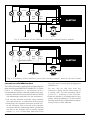
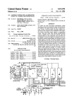
User Manual LokPilot Version 1.01 January 2002 LokPilot User Manual V1.01 01/2002 1 Important Warning Notice: General Properties : LokPilot is the universally usable locomotive receiver: It can be operated both with Märklin® Digital as well as with systems conforming to DCC.The LokPilot Decoder automatically detects the operating mode. It can be used with DC motors, coreless motors (e.g.Faulhaber) or AC Motors with HAMO magnets. LokPilots unique capabilities give you the flexibility and reliability that you expect from a modern digital decoder.Future standards are no problem for the LokPilot Decoder either: Its flash technology enables it to be updated at any time. Multi-protocol operation possible Fully utilisable in analog direct current and alternating current systems Fully automatic, on-the-fly change of all 4 operating modes (AC analog, DC analog,DCC digital, Märklin ® digital) 3rd generation Back EMF Control: With three CVs, adaptable to the locomotive motor High PWM frequency for silent operation: >15.5 kHz Lenz, Märklin® and ZIMO breaking units supported 14, 28 and 128 speed steps for DCC mode, 14 or 28 speed steps for Motorola® mode Automatic detection of the speed step settings in most DCC systems 2-digit or 4-digit locomotive addresses Conforms fully to NMRA The settings can be comfortably changed: The locomotive does not have to be opened 2 directionally dependent light outputs, each loadable with 140 mA 2 freely available functional outputs (F1 and F2), each loadable with 140 mA Total current of all 4 outputs: 300 mA Shunting gear switchable with F3 Deactivate the acceleration and braking periods with F4 Max. Motor output current: 1.1 A, overcurrent protected The LokPilot Decoder must only be used in model railways Avoid impact and pressure loads on the decoder Protect against water and dampness Never remove the heat shrink sleeve from the LokPilot decoder. Never solder immediately on the decoder, if necessary extend cable Never cover the decoder with insulating tape as this prevents heat discharge, and could therefore cause it to overheat The locomotive must always be deenergised for the installation No cable must ever come into contact with the metal parts of the locomotive. When assembling the locomotive, ensure that no cables are pinched or that short circuits created. Installation Prerequisites The locomotive must be in a perfect technical condition before doing the modification: Only a locomotive with faultless mechanics and clean analog running may be converted to digital operation. Wear parts such as motor brushes, wheel contacts, bulbs, etc. must be checked and cleaned or renewed if necessary. All the installation works must always be carried out on vehicles that have been removed from the tracks, and must be deenergised. Ensure that no voltage can reach the locomotive while the modifications are being carried out not even by accident. Pin 1 2 3 4 5 6 7 8 Function Color Right-hand motor connection Rear Lights power sink Function output F1 power sink Left-hand rail power pickup Left-hand motor connection Front lights power sink Common functions power (+) Right-hand rail power pickup orange yellow green black gray white blue red orange Total current of the decoder:1.2 ampere 1 8 Size:26.5 mm x 15.5 mm x 6.5 mm 2 7 Long--term investment security:Firmware upgrade possible through flash memory 3 6 4 5 gray Fig. 1: DCC plug according to NEM650/652 2 LokPilot User Manual V1.0 01/2002 green violet F1 F2 yellow white Rear light Front light LokPilot blau black red orange gray Motor Fig. 2: Connection of the LokPilot in locos with isolated function outputs green violet F1 F2 yellow white Rear light Front light locomotive chassis LokPilot orange black red gray Motor Fig. 3: Connection of the LokPilot in locos with function outouts wired to the loco chassis Locomotives with NEM Interface The LokPilot Decoder is supplied with a digital interface plug according to NEM650/652 (NMRA S9.1/9.2)(see Figure 1). Installation in locomotives with a corresponding interface is therefore particularly easy: Remove the vehicle housing. Ensure that you follow the dismantling instructions for the locomotive! Pull out the interface connector relay. Carefully store the connector in a safe place for future use. Now plug in the interface connector so that Pin 1 of the connector (this is the side of the decoder connector with the red/orange cable) is located at the side of the interface that is usually marked with an *,+, or 1. Ensure that, that none of the LokPilot User Manual V1.01 01/2002 plug pins cants or bends while plugging the connector in. Do not rely on the fact that the connector cable should lead away on a certain side: The sole deciding factor is the Pin 1 marking of the interface. Place the decoder in a suitable place in the model, mostly provided for. Fix the LokPilot Decoder with double-sided adhesive tape or (a very little) hot-melt adhesive. 3 Locomotives without DCC Interface Connecting Additional Functions First disconnect all the cable connections inside the locomotive to date and also note a connection via the locomotive chassis: The two motor connections must always be free of potential, i.e. there must be absolutely no connection to the chassis or the wheels/ current collectors.These are repeatedly overlooked, especially when modifying Fleischmann locomotives. After successfully connecting, remeasure all the connections using an ohmmeter; in particular you should search for short circuits between the motor and power pickup connections. You can attach as many consumers as you wish to the light and function outputs, as long as you do not exceed the maximum power consumption. However,you must ensure that the decoders overcurrent protection works very fast and that it switches off all functions together in case of emergency. The next steps depend on how the light and special functions within the locomotive are wired up: a) The lamps/ functions with their common connection are isolated from the locomotive housing (i.e. free of potential).The connection required is shown in Figure 2. b) The lamps/ functions are connected together against the locomotive ground (e.g. almost all Märklin® locomotives and older Fleischmann or ROCO locomotives). This case is illustrated in Figure 3. The red cable is connected to the right-hand power pickup (or the power pickup shoe in AC models), Connect the black cable to the left-hand power pickup (or wheel pickup in AC models). The orange cable is connected to the motor connection that was previously connected to the right-hand power pickup (or power pickup shoe in ACmodels), The grey cable is connected to the motor connection that was previously connected with the left-hand power pickup (or whell pickup in AC models). The reverse headlights are soldered onto the yellow cable and the forward headlights onto the white cable. Connect the green cable to the function that you wish to switch with F1. Connect the violet cable to the function that you wish to switch with F2. If your locomotive is wired up according to variant b), the connection is complete. Otherwise (see Figure 2), all the remaining connections of all the bulbs and functions must be connected together to the blue cable. This in turn must not have any contact with the locomotive chassis! 4 Therefore only use bulbs with 16V or higher and maximum 50 mA nominal current: Bulbs require a very high current when switched on, which could possible trigger the overcurrent protection of the decoder. Only use digital smoke generators in locomotives that are wired up according to Figure 2 e.g. Seuthe No.11. Other smoke units may require too much current. Some smoke generators on the market have over 250 mA power consumption! Locomotives that are wired up according to Figure 3 continue to require an analogue smoke unit as before. Ensure that the maximum permissible current for the function outputs is never exceeded and avoid short circuits between the outputs: The LokPilot Decoder is protected, however they will be destroyed if an external voltage is applied at the outputs of the LokPilot! Start-up We recommend that you carry out a functional test before reconnecting the locomotive. loco address 03 is preset in the factory. Does the locomotive travel in both directions? Switch the light on :Are the lights lit up? If you have installed the LokPilot Decoder in a locomotive with DCC interface connectors: Check whether the connector has been inserted in the interface the right way round. Motorola Operation The LokPilot Decoder can be used with all Märklin® appliances or compatible systems. However, the functions F1 to F4 can only be used with the socalled New Motorola ® Format .To activate this, the DIP switches 1 and 2 in the 6021 command station must be set to the upper position (On ). LokPilot User Manual V1.0 01/2002 Delta system owners have the problem that there is no available light switch there. Therefore the LokPilot can be adjusted so that the locomotive lights are permanently on (dependent of course on the direction of travel). You only have write the value 01 on CV 50 e.g. with the aid of a 6021. DCC Operation Remove any capacitors that might be incorporated in the connecting track (e.g. in the ROCO connecting track).These can disturb operation of the decoder. The Premium Digital Decoder can be run with any system that conforms to DCC. The automatic speed step detection has been tested with the following appliances: ROCO Lokmaus 2, Uhlenbrock Intellibox, Lenz Digital plus V2.3, ZIMO MX1. The detection does not function when operated with Lenz Digital plus V3.0 if you wish to run 14 speed steps. Use 28/ 128 speed steps. Each time that the Premium Digital Decoder receives a current (i.e. after the system is switched on) and the light is switched on it tries to detect the speed steps settings. If you switchover the speed steps settings during operation you must briefly switch off the current supply to the Premium Digital Decoder so that the automatic mode functions as desired. The detection takes up to 30 seconds. Enter the current decoder address (Alternative: 80) Actuate reverse direction at the master controller (turn the master controller to the left beyond the limit stop, until you hear a click), hold the controller where it is and then press the Go button The LokPilot Decoder is now in programming mode (The vehicle lights are now flashing) Now enter the number of the parameter (CV) that you want to change (two-digit number). Actuate the reverse direction to confirm (the lights now double-flash) Now enter the new value for the CV (twodigit number) Confirm by actuating reverse direction (Lights light up for about one second and then flash again) You can now enter other CVs that you wish to change Quit the programming mode by selecting CV 80 or by switching the track voltage off and then back on again (Press the Stop button on the 6021, then repress the Go button)) DCC Systems (Lenz, Intellibox, etc.) The detection can be switched off using CV 64 (see the table on Page 8). The CVs are much easier to change if you have a DCC-compatible digital system or an Intellibox. Please read the relevant chapter of your system manual (e.g.: Programming DCC decoders). The LokPilot Decoder supports all NMRA programming modes. Changing the decoder parameters Tips and Tricks The Premium Digital Decoder knows many parameters. A list is given at the end of these instructions. All the set values are stored in so-called CVs (configuration variables).These can be specifically changed,depending on the command station used. Adjust Back EMF Control Märklin 6021 (The master controller must be set to 0.There must be no other locomotives on the tracks.Look for the flashing signals of the locomotives!) Press the Stop and Go button of the 6021 simultaneously (together), until a reset is triggered.(Alternatively:briefly remove the transformer plug) Press the Stop button so that the track voltage is switched off LokPilot User Manual V1.01 01/2002 The LokPilot Decoder Back EMF Control can be adjusted to a wide range of different motors.The standard settings are very suitable for ROCO, Brawa, Kato, Liliput and similar locomotives using a can motor. You might have to experiment with others for a while. The values for the very frequent cases are given below: Parameters for Fleischmann Locomotives with the Fleischmann motor require the following settings: CV CV CV CV 2 51 52 53 = = = = 5 25 20 10 5 Parameters for Märklin ® high-power motor The Märklin ® 5-pole high power motor (Series 37xxx) is very well suited for the PremiumDigital Decoder,if you set the following parameters: CV CV CV 51 52 53 = = = 40 20 15 Parameters for Märklin ® motors with HAMO magnets Märklin ® universal motors can also be used with the Premium Digital Decoder after doing a modification installing a HAMO permanent magnet: CV CV CV CV 2 51 52 53 = = = = 6 14 20 15 Parameters for Locomotives with Coreless Motors Unfortunately,there are a large number of different coreless motors in use (e.g. Faulhaber,Maxxon,etc)so that we can only give the values for those locomotives commonly found. For Märklin® BR55 /17: CV CV CV 51 52 53 = = = 25 30 08 Decoder Reset You can reinstate the factory settings at any time if you cannot get any further: Simply write the value 08 in CV 08 Braking Units The LokPilot Decoder detects the Märklin®, Lenz (LG100) and ZIMO (MX9, MXHLU) braking units. Support of all braking units is active ex works. CV 57 offers a new function (ESU braking mode):This enables a path to be set that the locomotive passes through from the start of the braking section until it stops.This enables the locomotive to always come to a stop precisely in front of the red signal, independent of the locomotive s speed.The LokPilot then calculates how strongly the locomotive should brake. The larger the value in CV 57, the longer the stopping distances. If you enter a value of 0 , the normal mode is reactivated. Note: Enter 80 instead of 0 for the 6021. Support and Assistance Your model train or hobby shop is your competent partner for all your questions regarding LokPilot decoders. You may also contact us directly. For enquiries please use either email or fax (dont forget to provide your own fax-no.) and we will reply within a few days. Please call our hotline only in case of complex enquiries that cant be dealt with by email or fax. The hotline is often very busy you may encounter delays. Also check our website for more information. You will find many hints regarding FAQ and even feed back from other users. phone: ++49 (0)700 - LOKSOUND ++49(0)700 - 56576863 Tuesday from 10 am till 12 am fax : ++49 (0)7043 - 90 75 36 email: [email protected] mail: ESU electronic solutions ulm GmbH - technischer Support Am Tiefen See 5 D-75433 Maulbronn Internet: http://www.loksound.de However,we recommend that you switch off any braking units not required: For example,if you use a purely DCC environment, the Märklin® braking unit is unimportant and should therefore be switched off. CV 56 is responsible for the switching off. 6 LokPilot User Manual V1.0 01/2002 C V name description range of valuesdefault value 1 Loco address Adress of locomotive 01 - 127 03 2 Start voltage Sets the minimum speed of the locomotive 01 - 63 03 3 Acceleration This value multiplied by 0.869 is the time from stop to maximum speed 01 - 63 04 4 Deceleration This value multiplied by 0.869 is the time from maximum speed to stop 01 - 63 03 5 Maximum Speed Maximum speed of locomotive 01 - 63 63 6 Vmid Medium speed of locomotive 01 - 63 25 7 Version number Internal software version of LokPilot (read only) - - 8 Manufacturers ID Manufacturers version number (ID) of ESU - 151 17 Extended locomotive 18 address long address of locomotive CV 17 contains byte with higher value (bit 6 and bit 7 must always be active), CV18 contains byte with lower value. Only active when funktion in CV 29 is switched on (see below) 128-9999 0 29 Configuration register The most complex CV within the DCC Standard. This information is only relevant in DCC operation. - 4 01 or 02 01 01 or 02 02 00 - 79 56 52 Load Control param. 2 Parameter 2 ( K-segment). 00 - 79 Defines the effect of load control. The higher the value, the stronger the effect of Back EMF control. 32 Add the desired numbers to calculate the value of CV29. For example: 28 Speed steps + analogue operation = 2+4 = 6. function value Normal direction of travel Reverse direction of travel 0 1 14 speed steps (only for DCC Systems) 0 28 / 128 speed steps (only for DCC Systems) 2 Analogue Operation switched off Analogue Operation permitted 0 4 short addresses (CV1) in DCC operation 0 long addresses (CV17+18) in DCC operation 32 49 Back EMF control Enable or disable Back EMF Control: Back EMF Control (Load Control) activated Back EMF Control switched off 50 Märklin Delta Mode 1 2 Light control for Märklin Delta Operation Headlights are always on (Delta mode) Headlights switched with function (normal) 1 2 51 Load Control param. 1 Parameter 1 (motor control reference voltage) Defines the Back EMF voltage, which the motor should generate at maximum speed. The higher the efficiency, the higher this value may be set. If the locomotive does not reach maximum speed, reduce this parameter. LokPilot User Manual V1.01 01/2002 7 C V name description 53 Load control param. 3 parameter 3 ( I-segment). range of valuesdefault value 00 - 79 24 Defines the brightness of the function outputs. The higher the value, the brighter the lamps are. 01 - 16 16 Defines the allowed analogue modes 1,2 or 3 3 1,2,3 or 4 3 0 - 63 0 0, 1, 2 or 3 3 Defines momentum of motor. The higher the momenum of the motor (large flywheel or bigger diameter motor) the lower this value has to be set. 54 Dimmer 55 Analogue mode configuration 56 Braking modes 57 ESU-Braking mode function value AC Analogue Mode Enabled DC Analogue Mode Enabled AC and DC Analogue Modes Enabled 1 2 3 Defines the allowed Braking modes function value Märklin Braking mode Enabled ZIMO Braking mode Enabled Märklin and ZIMO Braking mode Enabled Disable all Braking modes 1 2 3 4 Settings for the ESU Braking mode. See the notes in the text. 64 DCC-Settings DCC-Speed step detection / ZIMO Manual Bit Only relevant in DCC operation. Add the desired numbers to calculate the value of CV29: funktion value Disable DCC speed step detection Enable DCC speed step detection (recomm.) 0 1 New ZIMO Manual function (MX2000) Old ZIMO Manual funktion (MX1) 0 2 Copyright 2001 by ESU electronic solutions Ulm GmbH. Electrical characteristics and dimensions are subject to change without prior notice. All rights reserved. ESU may not be held responsible for any damage or consequential loss or damage caused by inappropriate use of the product, abnormal operating conditions, unauthorized modifications to the product, etc. Not suitable for children under 3 years of age. Inappropriate use may result in injury due to sharp points and edges. Märklin® is a registered trademark of the company Gebr. Märklin® und Cie. GmbH, Göppingen, Germany. 8 LokPilot User Manual V1.0 01/2002