1
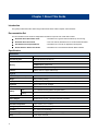
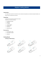
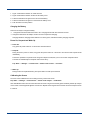
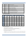
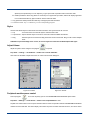
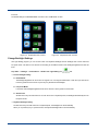
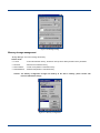
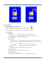
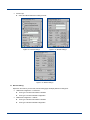
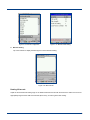
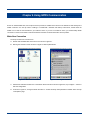
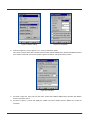
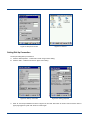
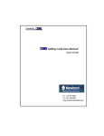
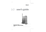
NLS-PT30 Series Mobile Computer User Guide © 2012 by Newland Auto-ID Tech. Co., Ltd. All rights reserved. Please carefully read the manual before use the product, and effectively to protect the safety of products operation. Please keep this manual after reading properly and save for the next reading. Do not disassemble the terminal or tearing the seal label on the terminal. Otherwise, FuJian Newland Auto-ID Tech. Co., Ltd. does not assume responsibility for the warranty or replacement. The pictures in this manual are for reference only. If the individual picture from the actual product was different with this manual, please refer to actual product. Regarding to the product modification and update, Newland Auto-ID Tech. Co., Ltd. reserves the right to make changes to any software or product to improve reliability, function, or design at any time without notice. This manual contains all the information is protected by copyright. Any Company and individuals should not in any way or reason for any form of extract, copy, sell all or part of this document without written permission. Newland Auto-ID Tech. Co., Ltd. 3F, Building A, No.1, Rujiang Xi Rd., Mawei, Fuzhou, Fujian, P.R. China. 350015. Web :http://www.nlscan.com Revision History Changes to the original manual are listed below: Revision Description Changed Date Ver 1.0 Initial release. 2012-04-12 Ver 1.1 Modify text mistakes 2012-05-16 Table of Contents Chapter 1 About This Guide............................................................................................................................................................................ 1 Introduction .................................................................................................................................................................................. 1 Documentation Set ..................................................................................................................................................................... 1 Specification ................................................................................................................................................................................ 1 Software Version......................................................................................................................................................................... 2 Chapter Descriptions.................................................................................................................................................................. 3 More Information......................................................................................................................................................................... 3 Service Information .................................................................................................................................................................... 3 Chapter 2 Getting Started ............................................................................................................................................................................... 4 Introduction .................................................................................................................................................................................. 4 Unpacking .................................................................................................................................................................................... 4 Accessories ................................................................................................................................................................................. 4 Getting Started ............................................................................................................................................................................ 4 Installing the Main Battery ................................................................................................................................................ 4 Charging the Battery ......................................................................................................................................................... 5 Power On, Suspend and Wake Up ................................................................................................................................. 5 Calibrating the Screen ...................................................................................................................................................... 5 Checking Battery Statues ................................................................................................................................................. 6 Installing MicroSD Card .................................................................................................................................................... 7 Installing SIM Card ............................................................................................................................................................ 7 Adjusting the Hand Strip ............................................................................................................................................................ 7 Chapter 3 Using the PT-30 Series ................................................................................................................................................................. 8 Introduction .................................................................................................................................................................................. 8 Status Icons ................................................................................................................................................................................. 8 Programs Icon ............................................................................................................................................................................. 9 Setting Programs Icon ..............................................................................................................................................................11 Keypads ..................................................................................................................................................................................... 12 Numeric Keypad input mode ......................................................................................................................................... 13 Function Keys Introduction ............................................................................................................................................ 13 Stylus .......................................................................................................................................................................................... 14 Adjust Volume ........................................................................................................................................................................... 14 Peripheral modules power control .......................................................................................................................................... 14 Change Backlight Settings ...................................................................................................................................................... 15 Memory storage management ................................................................................................................................................ 16 Resetting the PT30................................................................................................................................................................... 17 Warm reset: ...................................................................................................................................................................... 17 Cold reset: ........................................................................................................................................................................ 17 Locking the PT30 ...................................................................................................................................................................... 17 Barcode Settings ...................................................................................................................................................................... 18 Barcode engine parameter configuration ..................................................................................................................... 18 Reading 1D barcode ....................................................................................................................................................... 20 Reading 2D barcode ....................................................................................................................................................... 21 Chapter 4 Using Bluetooth Communication ............................................................................................................................................... 22 Chapter 5 UsingWiFi Communication ......................................................................................................................................................... 24 Chapter 6 Using GPRS Communication ..................................................................................................................................................... 29 Make New Connection ............................................................................................................................................................. 29 Setting Dial-Up Connection ..................................................................................................................................................... 31 Check GPRS Connection Status ............................................................................................................................................ 32 Chapter 7 Using ActiveSync ......................................................................................................................................................................... 33 Introduction ................................................................................................................................................................................ 33 Install .......................................................................................................................................................................................... 33 Synchronize Information .......................................................................................................................................................... 33 Chapter 8 Accessories ................................................................................................................................................................................... 34 Battery ........................................................................................................................................................................................ 34 Cradle ......................................................................................................................................................................................... 34 Put PT30 into cradle ....................................................................................................................................................... 34 Pick up PT30 from cradle ............................................................................................................................................... 34 Charging .................................................................................................................................................................................... 34 Use cradle charging ........................................................................................................................................................ 34 Use AC adaptor charging ............................................................................................................................................... 34 LED charging indicator ............................................................................................................................................................ 35 LED indicator for Scanning/Decoding/Communication ....................................................................................................... 35 Connect Host PC via USB cable ............................................................................................................................................ 35 Connect Host PC via Cradle ................................................................................................................................................... 35 Chapter 9 Maintenance& Troubleshooting ................................................................................................................................................. 36 Introduction ................................................................................................................................................................................ 36 Considerations on using PT30................................................................................................................................................ 36 Disassembly and modification ....................................................................................................................................... 36 Connect power source.................................................................................................................................................... 36 Abnormal situation .......................................................................................................................................................... 36 Drop Damage................................................................................................................................................................... 36 LCD Display ..................................................................................................................................................................... 36 Stacking heavy objects ................................................................................................................................................... 36 Placed location ................................................................................................................................................................ 36 Use occasion ................................................................................................................................................................... 36 Caution ............................................................................................................................................................................. 37 Battery safety guidelines ................................................................................................................................................ 37 Troubleshooting ........................................................................................................................................................................ 38 Chapter 1 About This Guide Introduction This guide provides information about using the NLS-PT30 series mobile computer and accessories. Documentation Set The documentation set for the NLS-PT30provides information for specific user needs and includes: NLS-PT30 Series Quick Start Guide :Describes how to get the NLS-PT30 Series up and running. NLS-PT30 Series User Guide :This is the manual, Describes how to use the NLS-PT30 Series. API Software Development Manual :Describes how to use API for application development. WinCE Software Utilities User Guide :Describes how to use Newland's WinCE utilities software. Specification Performance Processor Marvell XScale PXA310, 806MHz CPU Operation System Microsoft Windows CE.NET 6.0 256MB RAM 128MB ROM for system area Memory 2GB flash memory for user storage Interface RS232, USB 2.0, support USB charge Physical Dimensions (L x W x H) 189.5 x 76 x 45 mm (7.5 x 3 x 1.7 inch) Weight 382g (Including battery) Display 2.83” QVGA with backlight TFT Touch screen LCD, support sunlight readable Keyboard 30 Keys Numeric with backlight Notification Vibrator, Speaker and LED Battery Main 3.7V, 3000mAh Rechargeable Li-Polymer battery Backup 3.7V, 150mAh Rechargeable Li-Polymer battery (support 50hours data backup) Expansion MicroSD memory slot Power Adaptor Output: DC 5V, ≥ 1.5A; Input: AC 100~240V, 50~60Hz Environmental 1 Operation Temperature -10℃ to 50℃ (14℉ to 122℉) Storage Temperature -20℃ to 60℃ ( -4℉ to 140℉) Humidity 5% ~ 95% (non-condensing) Static Discharge ±15 kV (Air discharge), ±8 kV (Direct discharge) Drop 1.2 m drop to concrete Environmental Sealing IP54 sealing Barcode / RFID 1D Barcode 2D Barcode Laser (≥ 6 mil) Code128, EAN-13, EAN-8, Code-39, UPC-A, UPC-E, Codabar, Interleaved 2 of 5, CCD (≥ 4 mil) ISBN/ISSN, Code 93, etc. CMOS (≥ 5 mil) ALL 1D and PDF-417, QR Code, Data Matrix, Maxicode, Aztec, etc. RFID HF 13.56MHz, UHF 2.4GHz Wireless WLAN Summit IEEE 802.11 b/g, security support EAP, WEP, WPA, WPA2, 802.1X WWAN 2G GSM/GPRS (850, 900, 1800, 1900 MHz) 3G WCDMA (850, 900, 1800, 1900, 2100 MHz) or (900, 1800, 1900, 2100 MHz) WPAN Bluetooth Class II V2.0 Others GPS, Camera, Far Infrared, UHF RFID (Gen 2) Certificates FCC Part15 Class B, CE EMC Class B, CCC Software Version Firmware information query tool can detect and display terminal software and hardware version information and helpful future updates or maintenance. The firmware information query tool can detect the information: A. To determine the operation system version. B. To determine the firmware version. C. To determine the system configuration, production date and other information. D. To determine the version of WIFI module, and WIFI and Bluetooth MAC addresses. E. To determine the type and version of barcode engine. Tap “Start”→“Settings”→“Control Panel”→double clicks “Firmware Information”. Figure 1.1: Firmware Information 2 Chapter Descriptions Chapter 1, About This Guide : general description of this manual. Chapter 2, Getting Started : provides information on getting the PT30 Series up and running for the first time. Chapter 3, Using the PT30 Series : provides basic instructions for using the PT-30 Series, Chapter 4, Using Bluetooth : explains how to use Bluetooth functionality. Chapter 5, Using WiFi Communication : explainshow to use WiFi functionality. Chapter 6, Using GPRS Communication : explainshow to use WiFi functionality. Chapter 7, Using ActiveSync : synchronizes information on the mobile computer with information on Chapter 8, Accessories : describes the available accessories and how to use them with the the host computer PT-30 Series. Chapter 9, Maintenance & Troubleshooting : provides troubleshooting solutions for potential problems during PT-30 Series operation. More Information For more product and support information, please visit our web site: http://www.nlscan.com。 Service Information Newland China Phone +86-400-608-0591 Email [email protected] Newland Europe Phone +31(0)-345-870-033 Email [email protected] Newland Taiwan Phone +886-2-7731-5388 Email [email protected] Newland North America Phone +1-510-490-3888 Email [email protected] 3 Chapter 2 Getting Started Introduction This chapter lists the parts and accessories for the PT-30 Series and explains how to install and charge the batteries, and power on the PT-30 Series for the first time. Unpacking Carefully remove all protective material from the pack. Verify that you received the following: PT30 Mobile Computer USB cable AC adaptor Li-Polymer battery Tethered stylus Hand strap Quick Start Guide Accessories PT30 single slot cradle PT30 cradle AC adaptor USB cable Getting Started Installing the Main Battery 1 4 2 5 3 6 4 1. Figure 1 indicates the direction to unlock the latch. 2. Figure 2 indicates the direction to take out the battery cover. 3. Follow the instructions of figure 3 and 4 to insert the battery. 4. Follow the instructions of figure 5 to close down the battery cover. 5. Push the latch to the lock position. Charging the Battery There are two ways to charge the battery: Charge the terminal via USB connection to PC. Charging time should need around 8-10 hours. Charge the terminal via AC adaptor. Around 4 hours is required for charging. Charging indication: Charging status LED turn from red to green, indicates the battery charging complete. Power On, Suspend and Wake Up Power On: Long press the power button for 2-3 seconds to start the terminal. Suspend: During terminal in power on status, long press the power button for 2 seconds to turn terminal into suspend mode immediately. Terminal no operation in a period of time will go into suspend mode,when you turn on the auto suspend function. The timer for automatically into suspend mode can be set by: Tap “Start”→“Settings”→“Control Panel”→double clicks “Power”→“schemes”. Wake Up: During terminal in suspended status, press power button to wake up the terminal. Calibrating the Screen The touch screen calibration tool is for setting accuracy of the touch screen. Tap “Start”→“Settings”→“Control Panel”→ double clicks “Stylus”→”Calibration”. Click “Recalibrate” button then the screen becomes as shown in Figure 2.2.Carefully press and briefly hold the tip of stylus on the center of each target that appears on thescreen. Repeat as the target moves around the screen then tap the screen to continue. 5 Figure 2.1: Calibration Figure 2.2: Recalibrate Checking Battery Statues To check the charge status of the main battery in the terminal. Tap “Start”→“Settings”→”System”→double clicks“Power”. Figure 2.3: Power Properties Figure 2.4: Power Properties - Schemes Power schemes has four status; “Running”, “User Idle”, “System Idle” and “Suspend”: During operating, system is in "running" state. In running state, within the time set in the operating conditions no any operation, system turn to the user idle state. In user idle state, within the time set in the operating conditions no any operation, system turn to the system idle state. In system idle state, within the time set in the operating conditions no any operation, system turn to suspend state. 6 Installing MicroSD Card The MicroSD card slot provides secondary non-volatile storage. The slot is located under the battery. Refer to the documentation provided with the card for moreinformation, and follow the manufacturer’s recommendations for use. As shown below to install the MicroSD card, turn the card metal contact points face down then put into the slot. Please note the following situations will lead to the MicroSD card is not working: Card metal contact pads are not clean, battery voltage instability, the slot being squeezed, slot internal wire rust or bend excessively, the card infected with a virus, the card is not properly formatted, damaged cards, slot damage. Installing SIM Card The SIM card slot is located under the battery, and only support in GPRS model of PT-30 series. 1. Take out the battery and follow the figure 1 arrow indicate switch the SIM card cover to unlock position then open the card cover. 2. Turn the SIM card metal contact points face down then put into the slot. 3. Switch the SIM card cover to lock position. 1 2 3 Adjusting the Hand Strip The PT-30 Series handstrap is attached to the bottom of the terminal. Adjust the hand strap to increase comfort when holding the terminal for extended periods of time. 7 Chapter 3 Using the PT-30 Series Introduction This chapter provides the detailed instructions for using and setting the PT-30 Series. Figure 3.1: Desktop Icons Status Icons The status bar at the bottom of the screen can contain the status icons listed in Table 3.1 Table 3.1 Status Icons. Icon Description Bluetooth management tool. Lowercase input. In state of digital input, pressed ALPHA key. Uppercase input. In lowercase input state, pressed SHIFT key. Uppercase lock. In lowercase input state, double pressed SHIFT key. FUNC key pressed. IP information. 8 USB connection status. Indicates battery charging. WiFi signal status. Displays current time. Keyboard panel. Background running program selection window. Programs Icon Table 3.2 Software utilities icons. Icon 9 Program Name Description Stylus For the touch screen calibration settings. Light Setting For the screen and keyboard backlight settings. Peripheral Switch Used to offer power control function for peripheral module. Calculator For numeric calculation. UnitConver Unit conversion tool. Microsoft WordPad Mocrosoft WordPad text editing tool. LockConfig To keyboard and touch screen lock or unlock tool. Wi-Fi WiFi communication management and configuration tool. Bluetooth Device Properties Bluetooth communication management and configuration tool. Barcode Setting Barcode engine configuration tool. Autorun Setting the programs and parameters which need to boot automatically. SysBackupRestore Backup/Restore system registry, configuration and data in storage memory. Firmware Information For checking the system firmware information and version. Putty For Telnet terminal emulation tool. RegEdit System registry editing tool. uEasyFileCE Bluetooth file transfer utility. 10 Setting Programs Icon Icon Description System volume adjuster. Internet options setting tool. Enable/Disable connects with host PC. Memory storage management and configuration. Battery and devices power status and system power schemes settings. Password attributes (power on password and screen saver password) settings. System date, time and time zone settings. Region, language and input method settings. Dialing configuration. To remove programs that installed on the terminal. 11 Input panel setting. Owner properties setting. Network connects configuration. System information. Screen display interface and backlight configuration. View the information about certificates installed on the terminal. Keypads 12 1 SCAN key Barcode reading button. 2 TOOL key Pop-up shortcut menu, or perform shortcuts. 3 Backlight key Open or close screen backlight 4 ALPHA key Alpha or numeric input switching. 5 FUNC key User defined application function keys. 6 Power key To power on, sleep or wake up the terminal. 7 SHIFT key To switching upper or lower case letters. Numeric Keypad input mode On ALPHA key locked state Numeric Key 1st 2nd 3rd On ALPHA + SHIFT keylocked state 4th 1st 2nd 3rd 1 * 2 a b c A B C 3 d e f D E F 4 g h i G H I 5 j k l J K L 6 m n o M N O 7 p q r P Q R 8 t u v T U V 9 w x y W X Y s Z 4th S Z Function Keys Introduction FUNN key + Backlight key: Lock/ Unlock function. This locking function only work for one time then turn to unlock state automatically. ALPHA and FUNC key is an independent processing, operation will not overwrite each other. The SHIFT key is only works on the ALPHA key be pressed. ALPHA and SHIFT key combination types: The keyboard is in lowercase input state when the SHIFT key is not pressed. The status bar display lowercase icon. The SHIFT key pressed once. Status bar display uppercase icon and turn back to lowercase icon after pressed any 13 alpha key.If the pressed key is not an alpha key, to give up the SHIFT operation back to lowercase state. Double pressed the SHIFT key (within 0.5 seconds) turn to uppercase input state, statues bar display uppercase icon. Pressed the SHIFT key again would turn back to lowercase state. Long pressed or double pressed the TOOL key could popup the shortcut window. Pressed the TOOL key + a number key, run the corresponding program. Stylus Use the PT30 Series stylus to select items and enter information. The stylus functions as a mouse. Tap : Touch the screen once with the stylus to select the menu item. Tap and Hold : Tap and hold the stylus on an item to see a list of actions available for that item. Drag : Hold the stylus on the screen and drag across the screen to select text. Drag in a list to select multiple items. CAUTION: To prevent damage to the screen, do not use any device other than the Newlandprovided stylus. Adjust Volume Adjust the system volume using the tool program in control panel Tap “Start”→“Setting”→“ControlPanel”→double click “Volume & Sounds” Click and move the slider to adjust the volume on "Volume and Sounds" dialog box. Figure 3.2: Volume Figure 3.3: Sounds Peripheral modules power control This tool program is for users to quickly open or close GPRS/3G/Bluetooth/WIFI/RFID power switch. Tap“Start”→“Settings”→“ControlPanel”→double click “PeripheralSwitch” icon, Tap WiFi icon switch button to turn the power of WiFi module to on/off. The operation method of GPRS/3G/Bluetooth/RFID modules are same with WiFi. The switch display ”ON” means the power of module has been turned on, and “OFF” means 14 turned off. The default settings of GPRS/WiFi/RFID on PT30 is ’ON’, and Bluetooth is "OFF”. Figure 3.4:Peripheral Power Control 1 Figure 3.5:Peripheral Power Control 2 Change Backlight Settings Use Light Setting program you can set the screen and keyboard backlight. Screen backlight has normal mode and low-power mode. Use this tool can also be set according to the different needs of the backlight brightness and auto-off timer. Tap “Start”→“Settings”→“ControlPanel”→double click “Light Setting” as icon. Screen backlight setting: Normal Mode: The backlight brightness can be set from 0-10 grade. You can drag the selected bar or click the up or down arrow to set the grade.Touch the screen or press any key will activate the backlight. Low-power Mode: Low-power mode backlight brightness level can be set from 0 to the grade of normal mode. Switch Timer Set after how many seconds if there is no touch the screen or keyboard press, the backlight automatically turn into low-power mode. Keyboard backlight setting: Set after how many seconds if there is no keyboard press, the backlight turn off automatically When you no press any key in a period of time, the keyboard backlight will turn off automatically. 15 Figure 3.6: Backlight setting Memory storage management “Storage Manager” is a tool for manage the memory. Actions mode: Format :Format the selected memory, the data in memory will be destroyed after memory formatted. Dismount :Dismount the selected memory. New Partitions :Create a new partition in selected memory. DeletePartitions :Deletea exist partition in selected memory. Caution: The memory configuration changes will destroy all the data in memory, please contact with technical staff before change. Figure 3.7: Memory Configuration 16 Resetting the PT30 Warm reset: Press the reset button to warm reset the terminal. It will take around 6-10 seconds to restart the system. User data in memory will not to destroy. Cold reset: Cold reset the terminal by hold the power key and pressed reset button and release the power key when screen redisplay.It will take around 16-20 seconds system reloading and start again. Terminal will restart in factory default setting. User data in memory will destroy. You can use backup/restore tool to process your data. Notice:The battery cover must be closed before execute reset function, otherwise the terminal will turn into suspend mode. Locking the PT30 Use the device lock feature to prevent use of the device. Tap“Start”→“Settings”→“ControlPanel”→double click “LockConfig” 图 3.8: Lock configuration Below status you can lock the keyboard and touch screen. 17 A. Terminal not operation in a period of time or by FUNC key + backlight button. B. Pressed screen unlock button to unlock your terminal. icon. Figure 3.9: Lock state Figure 3.10: Unlock state Barcode Settings Barcode engine parameter configuration Tap“Start”→“Settings”→“ControlPanel”→double click “Barcode Settings” icon. Barcode Setting program include Normal setting, Barcode setting and Test three select pages. A. Normal Setting: Output Setting: Output via API : Use program API libraries control to get the barcode data. Output via keyboard : Output the barcode data to keyboard buffer to simulate keyboard input. Output via clipboard : Output the barcode data to clipboard. Decode Mode Setting: Decode Mode: One time read mode : Press key start to scanning barcode, and released key to stop scanning. Start scan by key press : Press key start to scanning barcode until read success or time out to stop scanning. Continue read mode : Continue scanning barcode until change the reading mode. Read control by API : Start or stop scanning barcode by API software control. Time Out: Setting the timer of time out for scanning barcode, default value is 4000ms. Prefix and Suffix Setting: Provided the barcode reading result plus prefix or suffix function. Trigger button Config: Enable/Disable the trigger key. Press “start set” button to disable the trigger key or press a trigger key to set a new one. 18 Decode Tips: Select the indicate method for reading success. Figure 3.11: Normal setting 1 Figure 3.12: Normal setting 2 Figure 3.13: Norma setting 3 B. Barcode Setting: Depend on the mode of your terminal, barcode setting page will display difference setting item. 19 1D Barcode configuration:(Laser/CCD) Each type of 1D barcode enables or disables. Each type of 1D barcode detail configuration. 2D Barcode configuration:(CMOS) Each type of 2D barcode enables or disables. Each type of 2D barcode detail configuration. Figure 3.14: Barcode configuration Figure 3.15: Barcode detail setting C. Barcode Testing Tap “Test” selection to display the below figure to test the barcode reading. Figure 3.16: Barcode test Reading 1D barcode Adjust the terminal barcode reading angle or the distance between barcode with terminal.Let the width of the scan line appropriately larger than the width of the barcode (about 4mm), in order to get the best reading. 20 Right and wrong way of reading: Reading 2D barcode The best reading distance and angle: A. Adjust the terminal focus lights aiming to the center of 2D barcode. B. Adjust the reading distance between the terminal with barcode around 5-20 cm. C. 21 Adjust the reading angle: The relative pitch angle (the α) with barcode and terminal is less than 45 degrees (0 is the best) The relative skew angle (the γ) with barcode and terminal is less than 45 degrees (5~20 is the best) The relative roll angle (the β) with barcode and terminal can be any angles (0~360 degrees). Chapter 4 Using Bluetooth Communication Click the Bluetooth iconin desktop status bar to display the BT Configuration dialog window as shown in figure 4.2. Figure 4.1: Desktop A. Figure 4.2: Basic setting page Basic setting page offer device name and pin code setting. You can select to use default pin code and setting your default pin code. B. Option setting page offer you to use different communication mode as shown in figure 4.3. Figure 4.3: Option setting page Figure 4.4: Service setting page C. Service setting page offer you to use virtual COM port service as shown in figure 4.4. D. Following figure offer pairing, searching devices and service functions. 22 E. Application program will take the initiative to connect the last time connected Bluetooth device to communication. Figure 4.5: Pair & Link page Figure 4.7: Service searching 23 Figure 4.6: Device searching Figure 4.8: Favorite page Chapter 5 UsingWiFi Communication A. Main Window The Main window provides an overview of the current wireless network connection configuration (Active Profile) The following image (in Figure 5.1) is the SCU Main windows for Windows CE. Figure 5.1: SCU Main Window Enable Radio/Disable Radio When the radio is enabled, select this button (which displays Disable Radio) to disable it. When the radio is disabled, select the same button (which now displays Enable Radio) to enable it. When disabled, the radio does not attempt to make a connection to an access point. Active Profile To displays the name of the active profile. Use the drop-down menu to select a different profile. Note: If ThirdPartyConfig is selected (and after the device goes through a power cycle), WZC (Windows Zero Configuration) or another application is used to configure the SSID, Auth Type, EAP Type, and Encryption settings. Status To indicates the current status of the Summit radio. Connection statuses include: Down - The radio is not recognized by Summit software and therefore is not associated and nor authenticated. Disabled - The radio is disabled. To enable the radio, tap Enable Radio located on the SCU Main window. When the radio is disabled, it does not attempt to make a connection to an access point. Not Associated - The radio has not established a connection to an access point. 24 Associated - The radio has established a connection to an access point. If the radio Encryption type is set to WEP or a pre-shared key (WPA-PSK or WPA2-PSK), it should now be capable of obtaining an IP address (either statically assigned or through DHCP) and passing traffic. If the radio Encryption type requires EAP authentication then an EAP Type must be properly configured in order for the device to obtain an IP address and be capable of passing traffic. <EAP type> Authenticated - The radio has established a connection to an access point and has completed EAP authentication successfully. Radio Type Indicates the type of radio installed in the device. For example: BG - Indicates a Summit 802.11g radio which supports 802.11b and 802.11g. ABG - Indicates a Summit 802.11a/g radio which supports 802.11a, 802.11b, and 802.11g. N - Indicates a Summit 802.11n radio which supports 802.11a, 802.11b, 802.11g, and 802.11n. B. Profile Window Profile settings are radio and security settings that are stored for each configuration profile. When a profile is selected as the active profile on the Main window, the settings for that profile become active. Notes: When the ThirdPartyConfig profile is selected, a power cycle must be performed. The following image (in Figure 5.2)is the SCU Profile windows for Windows CE Figure 5.2: SCU Profile Window Profile changes are not saved to the profile until you tap Commit. Using Scan to Create a Profile When you tap Scan on the Profile window, SCU displays a list of that are broadcasting their SSIDs. Figure 5.3 below is an example of a Scan window. 25 Figure 5.3: Scan Window Each row shows an AP's SSID, its received signal strength indication (RSSI), and whether or not data encryption is in use (true or false). You can sort the list by tapping on the column headers. If the scan finds more than one AP with the same SSID, the list displays the AP with the strongest RSSI and the least security. Every five seconds, the Scan window updates the RSSI value for each of the APs in the list. To scan for new APs and view an updated list, tap Refresh. If you are authorized as an administrator in SCU, you can create a profile for any SSID in the list. To create a profile, double-tap the row for the SSID; or tap the row and then tap Configure Figure 5.4: Scan Window If you tap Yes on the dialog box, then SCU creates a profile for that SSID, with the profile name being the same as the SSID (or the SSID with a suffix such as "_1" if a profile with the SSID as its name exists already). If the AP is using WEP, then SCU opens a dialog box in which you can specify WEP keys. If the AP is using EAP, then SCU opens a dialog box in which you can specify login credentials for the EAP type (which SCU assumes is LEAP). After you enter information on a dialog box, you return to the SCU Profile window, where you can view and edit profile settings. If you make any changes, then you must tap Commit to save the changes. C. Status Window 26 The Status window provides status information on the radio connection between the client device and the access point to which it's associated. The following image is the SCU Status windows for Windows CE. Figure 5.5: Status Window D. Diags Windows The Diagswindows enables you to troubleshoot connection issues with SCU. The following image is the SCU Diags windows for Windows CE. Figure 5.6:Diags window (Re)connect Initiate a reconnect of the radio: Disable and enable the radio, apply (or reapply) the current profile, attempt to associate to the wireless LAN, and attempt to authenticate to the wireless LAN. Release/Renew Obtain a new IP address through DHCP release/renew. Start Ping/Stop Ping Start a continuous ping to the address in the edit box next to the button. Once the button is tapped, its name and function changes to Stop Ping. Pings continue until you tap Stop Ping, move to a different SCU window (other than Diags or Status), exit SCU, or 27 remove the radio. E. Global Window Global settings include radio and security settings that apply to all profiles and settings that apply to SCU itself. An administrator can define and change most global settings on the Global window in SCU. The following image is the SCU Global windows for Windows CE Figure 5.7: Global window 28 Chapter 6 Using GPRS Communication Ensure an activated SIM card, from the phone service provider, is installed in the terminal. The default of PT30 already has a GPRS connection. You can tap “Start”→“Settings”→“ControlPanel”→“Network and Dial-up Connections”, double clicks the GPRS icon to start the communication if you located in China. If you are not located in China, you should modify GPRS connection or create a new GPRS connection follow the instruction of telecommunication service provider. Make New Connection The steps of make new connection are: A. Double click the Make New Connection icon as shown in figure 6.1. B. Naming the connection name as shown in figure 6.2 than tap Next button. Figure 6.1: Make New Connection Figure 6.2: Naming the connection C. Selected the “Wireless modem Port” in the field of "Select a mode" as shown in figure 6.3, tap “Configure…” button to start the configuration. D. As shown in figure 6.4, change the baud rate value to “115200” and keep other parameter in default value. then tap “Call Options” page. 29 Figure 6.3: Modem setting E. Figure 6.4: Port Setting As shown in figure 6.5, enter [+cgdcont=1,“IP”,“cmnet”] in the bottom of field. This “cmnet” means a service point of GPRS service provider. Different GPRS service provider offer different service name. Please contact with your service provider to get the information, and tap OK button to save it.” Figure 6.5: Call option F. As shown in figure 6.6, enter [*99***1#] into phone number field. Different GPRS service provider offer different number. Tap “Finish” save it G. As shown in figure 6.7, screen will display the "GPRS" new linker. Double clicks the GPRS icon to start the connection. 30 Figure 6.6 Set phone number Figure 6.7: Connect Setting Dial-Up Connection The step of setting dial-up connection is: A. Click the “Dial Properties…” button that is shown in figure 6.8 to setting. B. Click the “Edit…” button that is shown in figure 6.9 to setting. Figure 6.8: Dial-up connection C. Enter “G” in three input fields that is shown in figure 6.10, and click “OK” button to confirm. Then the screen return to upper page (figure 6.9),click “OK” button to confirm again. 31 Figure 6.9: Dialing properties D. Screen turn to figure 6.11, and click “Connect” button start connection. E. Wait around 3-5 seconds, the GPRS connection should be successes. Figure 6.10 Figure 6.11 Check GPRS Connection Status Click the “Dial Properties…“ icon in status bar as to open the dialog window shown as figure 6.12 to display the GPRS connection status. Figure 6.12 GPRS status 32 Chapter 7 Using ActiveSync Introduction Microsoft ActiveSync (version 4.5 or higher) on theHost computer is use to synchronize information on the mobile computer with the host computer. Install To install ActiveSync on the host computer, download version 4.5 or higher from the Microsoft web site at http://www.microsoft.com. Refer to the installation description included with the ActiveSync software. Figure 7.1 ActiveSync install interface Synchronize Information Figure 7.2: Synchronize detail information 33 Figure 7.3 Select synchronize item Chapter 8 Accessories Battery Terminal battery capacity too low will cause the terminal malfunction. Please charge the battery at less than 8 hours for sure the main battery and backup battery capacity was in full charge states. Cradle Put PT30 into cradle Pick up PT30 from cradle Charging Use cradle charging Use AC adaptor charging 34 LED charging indicator Red light long bright : During charge. Green light long bright : Charge complete. LED indicator for Scanning/Decoding/Communication Red light bright : During scan barcode. Green light bright : Success decoded barcode. Blue light flash : Communication module (BT/WIFI/GPRS/3G)during communication. Connect Host PC via USB cable 1. Open the USB port cover which is located in bottom of PT30. 2. Plug in USB cable connector to PT30 USB port and the other sides of cable connect to host PC. Notice: Please make sure the host PC already installed Microsoft ActiveSync before connection. Connect Host PC via Cradle 1. Put the PT30 into cradle. 2. Plug in USB cable connector to cradle USB port and the other sides of cable connect to host PC. Notice: Please make sure the host PC already installed Microsoft ActiveSync before connection. 35 Chapter 9 Maintenance& Troubleshooting Introduction This chapter includes considerations on operation and battery charging, and provides troubleshooting solutions for potential problems during the terminal operation. Considerations on using PT30 Disassembly and modification Please do not attempt to disassemble or modify the terminal, if cause the damage to the terminal, Newland does not assume warranty responsibility. Connect power source Please use the terminal original power adapter otherwise there is a risk of damage to the terminal. Abnormal situation Leave far away from fire source during battery charging. Turn off the power when you found abnormal odor, overheating or smoke situation and contact Newland service center, there is a risk of fire if continue charge. Drop Damage If the terminal caused the damage because drop down. Please turn off the power and contact with Newland service center for help. LCD Display Do not stress or impact LCD screen, it may cause the broken glass of the LCD panel. If the glass of the LCD panel is broken, please do not touch the liquid, for fear to cause skin burns or infection. Stacking heavy objects Do not place heavy objects stacked on the terminal in order to avoid heavy objects lose balance and fall over cause injury. Placed location Do not placed the terminal in unstable, too moisture or dust places. It may cause to fire or electric shock, and also do not placed in direct sunlight for a long time. Use occasion Due to the terminal wireless module electromagnetic waves radiation will affect some instruments, so in the particular occasion that prohibited to use the wireless devices, such as aircraft, gas stations. Please do not use the wireless terminal in these occasions. 36 Caution If the terminal lost power or abnormal cause can not boot up, try a hardware reset to start it, the method is to press the reset button with needles. The location of reset button, please refer to the related chapter. Please do not throw or drop the terminal to avoid the LCD screen is damaged or cause the program interrupt execution to make the memory data loss, or other consequences of affecting the normal operation. Clean the reading window periodically. Do not touch the transparent glass of the scanning window to avoid scratch or stain glass affecting reading performance. Please do not use sharp objects to touch the screen, it may cause the screen is damaged or the internal short circuit. Please use a soft and dry cloth to wipe the terminal, and do not use a damp cloth, benzene, thinner or other volatile Do not let the terminal face down in order to avoid the keyboard disoperation. The environment temperature great change will lead to the terminal surface condensation, please dry the terminal chemicals to avoid the terminal keyboard and shell variant of aging. before use. Battery safety guidelines Battery in fire will cause an explosion. Battery can charge and discharge at least more than 500 times. Please renew the battery when the battery noticeably in shorter battery life. Using the battery only provided from Newland, and also use the power adapter only provided from Newland to Please unplugged the adapter when battery was fully charged, and do not continue to charge the battery. Since charge the battery. overcharging may shorten battery life. A fully charged battery is left unused, the battery will gradually discharge. It will not cause any abnormal states. 37 Do not use the damage or abnormal battery or adaptor already. Please correctly collect and dispose of the battery, and do not dispose the battery as general garbage. Troubleshooting Problem Cause & Solution Type Keyboard Description Keyboard malfunction or May be the keyboard components damage or cable loose contact between wrong character display. with main board socket. Please contact Newland maintenance or after service center. Battery Battery indicator doesn't light Check the adapter plugged in power outlet or contact with the terminal is well when charging. or not. Battery noticeably in short Check the battery whether is fully charged or malfunction. battery life. Replace a battery if the battery is malfunction. Battery is depleted. Replace the battery. USB cannot communication. Make sure the communication cable is plugged in well. Make sure the connector or port whether is obstruction. USB If there is no above situation, it may be the components failure, please contact the maintenance or after service center. Cannot see characters on Check the terminal whether is powered on. display. Check the terminal whether is in suspended mode. Wake up the terminal first if yes. Check the battery whether is in low states. Recharging the battery if yes. LCD Check the battery whether is poor contact. Reload the battery if yes. Screen Check the battery whether is depleted. Replace the battery if yes. If there is no above situation, it may be the components failure, please contact the maintenance or after service center. Does not power on. Battery is in too low states may cause cannot turn on. Charging the battery over 8 hours then try again. Replaced a battery if the battery was damage. If there is no above situation, it may be the components failure, please contact the maintenance or after service center. System System crash. Possible the user application to cause the terminal crashes, please check your application whether is safe. May be the terminal accidental power down, please use the needles to reset the terminal. If reset does not work, try use cold reset to reboot the system. 38