1
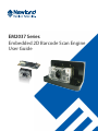
EM2037 Series
Embedded 2D Barcode Scan Engine
User Guide
Disclaimer
© 2013-2015 Fujian Newland Auto-ID Tech. Co., Ltd. All rights reserved.
Please read through the manual carefully before using the product and operate it according to the manual. It
is advised that you should keep this manual for future reference.
Do not disassemble the device or remove the seal label from the device. Otherwise, FuJian Newland Auto-ID
Tech. Co., Ltd. does not assume responsibility for the warranty or replacement.
All pictures in this manual are for reference only and actual product may differ. Regarding to the product
modification and update, FuJian Newland Auto-ID Tech. Co., Ltd. reserves the right to make changes to any
software or product to improve reliability, function, or design at any time without notice. Besides, the
information contained herein is subject to change without prior notice.
The products depicted in this manual may include software copyrighted by FuJian Newland Auto-ID Tech. Co.,
Ltd or a third party. The user, corporation or individual, shall not duplicate, in whole or in part, distribute,
modify, decompile, disassemble, decode, reverse engineer, rent, transfer or sublicense such software without
prior written consent from the copyright holders.
This manual is copyrighted. No part of this publication may be reproduced or used in any form without written
permission from Newland.
FuJian Newland Auto-ID Tech. Co., Ltd. reserves the right to make final interpretation of the statement above.
FuJian Newland Auto-ID Tech. Co., Ltd.
3F, Building A, No.1, Rujiang Xi Rd., Mawei, Fuzhou, Fujian, China 350015.
http://www.nlscan.com
Revision History
Version
Description
Date
V1.0.0
Initial release.
January 4, 2013
V1.0.1
Corrected inappropriate expressions and misspellings
January 17, 2013
V1.0.2
Replaced hard-to-read barcodes
April 9, 2013
Updates:
1. Added the Obtain Firmware Version feature in Chapter 1.
2. Added the USB HID-KBW Fast Mode, Speed features and modified the Emulate
Numeric Keypad feature in Chapter 2.
3. Added the Power LED feature in Chapter 6.
4. Added the Modify ISSN Code ID and Modify Micro PDF417 Code ID barcodes in
V1.1.0
Chapter 7.
5. Added the UPC-E/UPC-A Preamble Character, Convert UPC-E to UPC-A,
Convert Code 39 to Code 32 (Italian Pharma Code), Code 32 Prefix, Set Length
Range for UCC/EAN-128 and Micro QR features and two symbologies of ISSN
and Micro PDF417 in Chapter 8.
Note: You must have firmware version V3.06.071 or higher to use the new
features above.
January 5, 2015
Table of Contents
Revision History .............................................................................................................................................- 3 Chapter 1 Getting Started .................................................................................................................................. 1
Introduction .............................................................................................................................................. 1
About This Guide ..................................................................................................................................... 1
Document Set .......................................................................................................................................... 1
Connecting EVK to PC ............................................................................................................................ 1
Barcode Scanning.................................................................................................................................... 2
Barcode Programming ............................................................................................................................. 2
Factory Defaults ....................................................................................................................................... 3
Custom Defaults ...................................................................................................................................... 3
Product Information ................................................................................................................................. 4
Chapter 2 Communication Interfaces .............................................................................................................. 5
Introduction .............................................................................................................................................. 5
Serial Communication Interface .............................................................................................................. 5
Baud Rate .......................................................................................................................................... 6
Parity Check ...................................................................................................................................... 7
Data Bit .............................................................................................................................................. 7
Stop Bit .............................................................................................................................................. 8
Hardware Flow Control ...................................................................................................................... 8
USB Interface........................................................................................................................................... 9
USB-DataPipe ................................................................................................................................... 9
USB HID-KBW ................................................................................................................................... 9
Fast Mode ........................................................................................................................................ 10
USB HID-KBW Speed ..................................................................................................................... 11
USB Country Keyboard Types ........................................................................................................ 12
Country Code Table (Appendix 5) ................................................................................................... 12
Beep on Unknown Character .......................................................................................................... 13
Emulate ALT+Keypad ...................................................................................................................... 13
Function Key Mapping ..................................................................................................................... 14
Inter-Keystroke Delay ...................................................................................................................... 15
Caps Lock ........................................................................................................................................ 15
Convert Case ................................................................................................................................... 16
Emulate Numeric Keypad ................................................................................................................ 17
USB COM Port Emulation ............................................................................................................... 18
HID-POS .......................................................................................................................................... 18
Acquire Scanned Data ..................................................................................................................... 19
VID/PID ............................................................................................................................................ 19
IBM SurePOS(Tabletop) .................................................................................................................. 20
IBM SurePOS (Handheld) ............................................................................................................... 20
Chapter 3 Scan Mode ....................................................................................................................................... 21
Trigger Mode .......................................................................................................................................... 21
Auto Mode .............................................................................................................................................. 21
Decode Session Timeout................................................................................................................. 22
Timeout between Decodes (Same Barcode) .................................................................................. 23
Continuous Mode ................................................................................................................................... 24
Timeout between Decodes (Same Barcode) .................................................................................. 25
Chapter 4 Scanning Preferences .................................................................................................................... 26
Introduction ............................................................................................................................................ 26
Regular Mode/Mobile Phone Mode ....................................................................................................... 26
Decode Area .......................................................................................................................................... 26
Whole Area Decoding ...................................................................................................................... 26
Central Area Decoding .................................................................................................................... 27
Specify Central Area ........................................................................................................................ 28
Chapter 5 Illumination & Aiming ..................................................................................................................... 29
Illumination ............................................................................................................................................. 29
Aiming .................................................................................................................................................... 30
Chapter 6 Beep & LED Indications ................................................................................................................. 31
Introduction ............................................................................................................................................ 31
Startup Beep .......................................................................................................................................... 31
Good Read Beep ................................................................................................................................... 31
Beep Type ........................................................................................................................................ 32
Beep Volume ................................................................................................................................... 32
Additional Settings for Type 1 .......................................................................................................... 33
Beep Duration .................................................................................................................................. 33
Beep Frequency .............................................................................................................................. 34
LED Notification ..................................................................................................................................... 35
Good Read LED Notification ........................................................................................................... 35
LED Notification Duration for Good Read ....................................................................................... 35
Power LED....................................................................................................................................... 36
Chapter 7 Data Formatting .............................................................................................................................. 37
Introduction ............................................................................................................................................ 37
General Settings .................................................................................................................................... 38
Enable/Disable All Prefix/Suffix ....................................................................................................... 38
Prefix Sequences ............................................................................................................................ 38
AIM ID Prefix .......................................................................................................................................... 39
Code ID Prefix........................................................................................................................................ 39
Restore All Default Code IDs ........................................................................................................... 40
Modify Code ID ................................................................................................................................ 40
Custom Prefix ........................................................................................................................................ 44
Enable/Disable Custom Prefix ......................................................................................................... 44
Set Custom Prefix ............................................................................................................................ 44
Custom Suffix ......................................................................................................................................... 45
Enable/Disable Custom Suffix ......................................................................................................... 45
Set Custom Suffix ............................................................................................................................ 45
Data Packing .......................................................................................................................................... 46
Normal Pack .................................................................................................................................... 46
Terminating Character Suffix ................................................................................................................. 47
Enable/Disable Terminating Character Suffix .................................................................................. 47
Set Terminating Character Suffix ..................................................................................................... 48
Chapter 8 Symbologies ................................................................................................................................... 49
General Settings .................................................................................................................................... 49
Enable/Disable All Symbologies ...................................................................................................... 49
Enable/Disable 1D Symbologies ..................................................................................................... 49
Enable/Disable 2D Symbologies ..................................................................................................... 49
1D Symbologies ..................................................................................................................................... 50
Code 128 ......................................................................................................................................... 50
Restore Factory Defaults ................................................................................................................. 50
Enable/Disable Code 128 ................................................................................................................ 50
Set Length Range for Code 128...................................................................................................... 50
GS1-128 (UCC/EAN-128) ............................................................................................................... 51
Restore Factory Defaults ................................................................................................................. 51
Enable/Disable GS1-128 ................................................................................................................. 51
Set Length Range for GS1-128 ....................................................................................................... 51
EAN-8 .............................................................................................................................................. 52
Restore Factory Defaults ................................................................................................................. 52
Enable/Disable EAN-8 ..................................................................................................................... 52
Transmit Check Digit ....................................................................................................................... 52
Add-On Code ................................................................................................................................... 53
EAN-8 Extension ............................................................................................................................. 54
EAN-13 ............................................................................................................................................ 55
Restore Factory Defaults ................................................................................................................. 55
Enable/Disable EAN-13 ................................................................................................................... 55
Transmit Check Digit ....................................................................................................................... 55
Add-On Code ................................................................................................................................... 56
ISBN................................................................................................................................................. 57
Restore Factory Defaults ................................................................................................................. 57
Enable/Disable ISBN ....................................................................................................................... 57
Set ISBN Format.............................................................................................................................. 57
UPC-E .............................................................................................................................................. 58
Restore Factory Defaults ................................................................................................................. 58
Enable/Disable UPC-E .................................................................................................................... 58
Transmit Check Digit ....................................................................................................................... 58
Add-On Code ................................................................................................................................... 59
UPC-E Preamble ............................................................................................................................. 60
Convert UPC-E to UPC-A................................................................................................................ 60
UPC-A .............................................................................................................................................. 61
Restore Factory Defaults ................................................................................................................. 61
Enable/Disable UPC-A .................................................................................................................... 61
Transmit Check Digit ....................................................................................................................... 61
Add-On Code ................................................................................................................................... 62
UPC-A Preamble ............................................................................................................................. 63
Interleaved 2 of 5 ............................................................................................................................. 64
Restore Factory Defaults ................................................................................................................. 64
Enable/Disable Interleaved 2 of 5 ................................................................................................... 64
Set Length Range for Interleaved 2 of 5 ......................................................................................... 64
Check Digit Verification.................................................................................................................... 65
Set Discrete Lengths for Interleaved 2 of 5 ..................................................................................... 66
ITF-14 .............................................................................................................................................. 67
ITF-6 ................................................................................................................................................ 68
Matrix 2 of 5 ..................................................................................................................................... 69
Restore Factory Defaults ................................................................................................................. 69
Enable/Disable Matrix 2 of 5 ........................................................................................................... 69
Set Length Range for Matrix 2 of 5 ................................................................................................. 69
Check Digit Verification.................................................................................................................... 70
Code 39 ........................................................................................................................................... 71
Restore Factory Defaults ................................................................................................................. 71
Enable/Disable Code 39 .................................................................................................................. 71
Set Length Range for Code 39........................................................................................................ 71
Check Digit Verification.................................................................................................................... 72
Transmit Start/Stop Character ......................................................................................................... 73
Enable/Disable Code 39 Full ASCII ................................................................................................ 73
Convert Code 39 to Code 32 ........................................................................................................... 74
Code 32 Prefix ................................................................................................................................. 74
Codabar ........................................................................................................................................... 75
Restore Factory Defaults ................................................................................................................. 75
Enable/Disable Codabar.................................................................................................................. 75
Set Length Range for Codabar ....................................................................................................... 75
Check Digit Verification.................................................................................................................... 76
Transmit Start/Stop Character ......................................................................................................... 77
Start/Stop Character Format ............................................................................................................ 77
Code 93 ........................................................................................................................................... 78
Restore Factory Defaults ................................................................................................................. 78
Enable/Disable Code 93 .................................................................................................................. 78
Set Length Range for Code 93........................................................................................................ 78
Check Digit Verification.................................................................................................................... 79
GS1-Databar (RSS) ......................................................................................................................... 80
Restore Factory Defaults ................................................................................................................. 80
Enable/Disable GS1 Databar .......................................................................................................... 80
Transmit Application Identifier “01” .................................................................................................. 80
GS1 Composite Code...................................................................................................................... 81
Restore Factory Defaults ................................................................................................................. 81
Enable/Disable GS1 Composite Code ............................................................................................ 81
EAN/UPC Composite ...................................................................................................................... 81
Code 11............................................................................................................................................ 82
Restore Factory Defaults ................................................................................................................. 82
Enable/Disable Code 11 .................................................................................................................. 82
Set Length Range for Code 11 ........................................................................................................ 82
Transmit Check Digit ....................................................................................................................... 83
Check Digit Verification.................................................................................................................... 83
Industrial 2 of 5 ................................................................................................................................ 84
Restore Factory Defaults ................................................................................................................. 84
Enable/Disable Industrial 2 of 5....................................................................................................... 84
Set Length Range for Industrial 2 of 5 ............................................................................................ 84
Check Digit Verification.................................................................................................................... 85
Standard 25 ..................................................................................................................................... 86
Restore Factory Defaults ................................................................................................................. 86
Enable/Disable Standard 25 ............................................................................................................ 86
Set Length Range for Standard 25 .................................................................................................. 86
Check Digit Verification.................................................................................................................... 87
Plessey ............................................................................................................................................ 88
Restore Factory Defaults ................................................................................................................. 88
Enable/Disable Plessey ................................................................................................................... 88
Set Length Range for Plessey......................................................................................................... 88
Check Digit Verification.................................................................................................................... 89
MSI-Plessey..................................................................................................................................... 90
Restore Factory Defaults ................................................................................................................. 90
Enable/Disable MSI-Plessey ........................................................................................................... 90
Set Length Range for MSI-Plessey ................................................................................................. 90
Transmit Check Digit ....................................................................................................................... 91
Check Digit Verification.................................................................................................................... 91
ISSN................................................................................................................................................. 92
Restore Factory Defaults ................................................................................................................. 92
Enable/Disable ISSN ....................................................................................................................... 92
2D Symbologies ..................................................................................................................................... 93
PDF417 ............................................................................................................................................ 93
Restore Factory Defaults ................................................................................................................. 93
Enable/Disable PDF417 .................................................................................................................. 93
Set Length Range for PDF417 ........................................................................................................ 93
PDF417 Inverse ............................................................................................................................... 94
PDF417 Twin Code.......................................................................................................................... 95
Micro PDF417 .................................................................................................................................. 96
Restore Factory Defaults ................................................................................................................. 96
Enable/Disable Micro PDF417 ........................................................................................................ 96
Set Length Range for Micro PDF417 .............................................................................................. 96
QR Code .......................................................................................................................................... 97
Restore Factory Defaults ................................................................................................................. 97
Enable/Disable QR Code ................................................................................................................ 97
Set Length Range for QR Code ...................................................................................................... 97
QR Twin Code ................................................................................................................................. 98
Micro QR .......................................................................................................................................... 98
Aztec Code ...................................................................................................................................... 99
Restore Factory Defaults ................................................................................................................. 99
Enable/Disable Aztec Code ............................................................................................................. 99
Set Length Range for Aztec Code ................................................................................................... 99
Read Multi-barcodes on an Image ................................................................................................ 100
Set the Number of Barcodes ......................................................................................................... 101
Data Matrix .................................................................................................................................... 102
Restore Factory Defaults ............................................................................................................... 102
Enable/Disable Data Matrix ........................................................................................................... 102
Set Length Range for Data Matrix ................................................................................................. 102
Rectangular Barcode ..................................................................................................................... 103
Data Matrix Inverse........................................................................................................................ 103
Data Matrix Twin Code .................................................................................................................. 104
Maxicode ....................................................................................................................................... 105
Restore Factory Defaults ............................................................................................................... 105
Enable/Disable Maxicode .............................................................................................................. 105
Set Length Range for Maxicode .................................................................................................... 105
Chinese Sensible Code ................................................................................................................. 106
Restore Factory Defaults ............................................................................................................... 106
Enable/Disable Chinese Sensible Code ....................................................................................... 106
Set Length Range for Chinese Sensible Code ............................................................................. 106
Chinese Sensible Code Inverse .................................................................................................... 107
Chapter 9 Troubleshooting ........................................................................................................................... 108
FAQ ...................................................................................................................................................... 108
Appendix ......................................................................................................................................................... 110
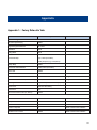
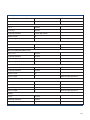
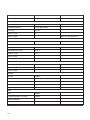
Appendix 1: Factory Defaults Table ..................................................................................................... 110
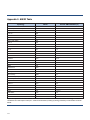
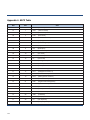
Appendix 2: AIM ID Table .................................................................................................................... 117
Appendix 3: Code ID Table .................................................................................................................. 118
Appendix 4: ASCII Table ...................................................................................................................... 119
Appendix 5: Country Code Table ......................................................................................................... 123
Appendix 6: ASCII Function Key Mapping Table ................................................................................. 124
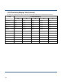
Appendix 7: Symbology ID Number .................................................................................................... 126
Appendix 8: Parameter Programming Examples ................................................................................ 127
a. Program the Decode Session Timeout ..................................................................................... 127
b. Program the Timeout between Decodes (Same Barcode) ....................................................... 127
c. Program the Central Area .......................................................................................................... 127
d. Program the Duration of Good Decode Beep (Type 1) ............................................................. 128
e. Program the Frequency of Good Decode Beep (Type 1) ......................................................... 128
f. Program the LED Notification Duration for Good Decode ......................................................... 128
g. Program the Custom Prefix/Suffix ............................................................................................. 129
h. Program the Terminating Character Suffix ................................................................................ 129
i. Program the Code ID .................................................................................................................. 129
j. Program the Length Range (Maximum/Minimum Lengths) for a Symbology ............................ 130
k. Program the Discrete Lengths for Interleaved 2 of 5 ................................................................ 131
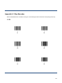
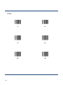
Appendix 9: F-Key Barcodes ............................................................................................................... 132
Appendix 10: Digit Barcodes ............................................................................................................... 134
Appendix 11: Save/Cancel Barcodes .................................................................................................. 136
Enter Setup
Chapter 1 Getting Started
Introduction
The EM2037 series embedded 2D barcode scan engines are armed with CMOS image capturer and the Newland patented
, a computerized image recognition system, featuring fast scanning and accurate decoding on barcodes on virtually
any medium - paper, magnetic card, mobile phones and LCD displays. The EM2037s can be easily integrated into OEM
equipments or systems, such as hand-held, portable, or stationary barcode scanners.
Moreover, the EM2037s open image acquisition interface, data interface and I/O interface to OEM developers to allow their
special integration needs. EM2037 Software Development Kit is provided for easy and quick development of OEM
applications.
About This Guide
This guide provides programming instructions for the EM2037. Users can configure the EM2037 by scanning the
programming barcodes included in this manual.
The EM2037 has been properly configured for most applications and can be put into use without further configuration. Users
may check the Factory Defaults Table in Appendix for reference. Throughout the manual, programming barcodes marked
with asterisks (**) are factory default values.
Document Set
EM2037 related documents include:
NLS-EM2037 Series Embedded 2D Barcode Scan Engine
Integration Manual:
NLS-EM2037 Series Embedded 2D Barcode Scan Engine
User Guide:
Describes how to integrate the EM2037.
Sample Barcodes:
Provides sample barcodes for testing the EM2037.
Describes how to use and program the EM2037.
Connecting EVK to PC
The supplied EM2037 EVK tool can assist users in application development for the EM2037. You can connect EM2037 EVK
to PC via a USB connection or an RS-232 connection. In case of USB connection, a driver is required if EVK wants to
communicate with EM2037 and receive decoded data through virtual serial port.
1
**Exit Setup
Enter Setup
Barcode Scanning
Powered by area-imaging technology and Newland patented
technology, the EM2037 features fast scanning and
accurate decoding. Barcodes rotated at any angle can still be read with ease. When scanning a barcode, simply center the
aiming beam or pattern projected by the EM2037 over the barcode.
Barcode Programming
Scanning the Enter Setup barcode can enable the engine to enter the setup mode. Then you can scan a number of
programming barcodes to configure your engine. To exit the setup mode, scan the Exit Setup barcode.
If the engine has exited the setup mode, only some special programming barcodes, such as the Enter Setup barcode and
Restore All Factory Defaults barcode, can be read.
Enter Setup
** Exit Setup
Programming barcode data can be transmitted to the Host. Scan the appropriate barcode below to enable or disable the
transmission of programming barcode data (i.e. the characters under programming barcode) to the Host.
Transmit Programming Barcode Data
** Exit Setup
** Do Not Transmit Programming Barcode Data
2
Enter Setup
Factory Defaults
Scanning the following barcode can restore the engine to the factory defaults. See Appendix 1: Factory Defaults Table for
more information.
Restoring the engine to factory defaults will not remove custom defaults stored on the engine.
Restore All Factory Defaults
Note: Use this feature with discretion.
Custom Defaults
Scanning the Restore All Custom Defaults barcode can reset all parameters to the custom defaults. Scanning the Save as
Custom Defaults can set the current settings as custom defaults.
Custom defaults are stored in the non-volatile memory.
Save as Custom Defaults
3
Restore All Custom Defaults
**Exit Setup
Enter Setup
Product Information
Obtain Product Information: Transmit the product information to the Host straight away via the communication interface.
Obtain Firmware Version: Transmit the firmware version to the Host straight away via the communication interface.
Obtain Product Information
Obtain Firmware Version
Send Product Information at Startup: Transmit the product information to the Host when the engine is powered on. This
feature only applies to engines using a serial communication interface.
Send Product Information at Startup
** Exit Setup
** Do Not Send Product Information at Startup
4
Enter Setup
Chapter 2 Communication Interfaces
Introduction
The EM2037 engine provides a TTL-232 interface and a USB interface to communicate with the host device. The host
device can receive scanned data and send commands to control the engine or to access/alter the configuration information
of the engine via the TTL-232 or USB interface.
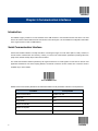
Serial Communication Interface
Serial communication interface is usually used when connecting the engine to a host device (like PC, POS). However, to
ensure smooth communication and accuracy of data, you need to set communication parameters (including baud rate,
parity check, data bit and stop bit) to match the host device.
The serial communication interface provided by the engine is based on TTL-level signals. TTL-232 can be used for most
application architectures. For those requiring RS-232, an external conversion circuit is needed. The conversion circuit is
available only to some models.
Serial Communication
Default serial communication parameters are listed below. Make sure all parameters match the host requirements.
Parameter
5
Factory Default
Serial Communication
Standard TTL-232
Baud Rate
9600
Parity Check
None
Number of Data Bits
8
Number of Stop Bits
1
Hardware Auto Flow Control
None
**Exit Setup
Enter Setup
Baud Rate
Baud rate is the number of bits of data transmitted per second. Set the baud rate to match the Host requirements.
** Baud Rate 9600
Baud Rate 19200
Baud Rate 1200
Baud Rate 38400
Baud Rate 2400
Baud Rate 57600
Baud Rate 4800
Baud Rate 115200
Baud Rate 14400
** Exit Setup
6
Enter Setup
Parity Check
** None
Even Parity
Odd Parity
** 8 Data Bits
6 Data Bits
7 Data Bits
5 Data Bits
Data Bit
7
**Exit Setup
Enter Setup
Stop Bit
** 1 Stop Bit
2 Stop Bits
Hardware Flow Control
If this feature is enabled, the engine determines whether to transmit data based on CTS signal level. When CTS signal is at
low level which means the serial port’s cache memory of receiving device (such as PC) is full, the engine will not send data
through serial port until CTS signal is set to high level by receiving device. When the engine is not ready for receiving, it will
set RTS signal to low level. When sending device (such as PC) detects it, it will not send data to the engine any more to
prevent data loss.
If this feature is disabled, reception/transmission of serial data will not be influenced by RTS/CTS signal.
Enable Hardware Flow Control
** Disable Hardware Flow Control
Note: Before enabling this feature, make sure that RTS/CTS signal line is contained in RS-232 cable. Without the signal
line, serial communication errors will occur.
** Exit Setup
8
Enter Setup
USB Interface
USB-DataPipe
A driver is required when using this protocol to communicate with the engine. Its advantages include fast data transmissoin
and easy to use.
USB-Datapipe
USB HID-KBW
When you connect the engine to the Host via a USB connection, you can enable the USB HID-KBW feature by scanning
the barcode below. Then engine’s transmission will be simulated as USB keyboard input. The Host receives keystrokes on
the virtual keyboard. It works on a Plug and Play basis and no driver is required.
USB HID-KBW
9
**Exit Setup
Enter Setup
Fast Mode
When Fast Mode On is selected, the engine sends characters to the Host faster. If the Host drops characters, do not use
Fast Mode.
** Fast Mode Off
** Exit Setup
Fast Mode On
10
Enter Setup
USB HID-KBW Speed
This parameter specifies the USB poll rate for a USB keyboard. If the Host drops characters, change the poll rate to a
bigger value.
11
1ms
2ms
3ms
** 4ms
5ms
6ms
7ms
8ms
9ms
10ms
**Exit Setup
Enter Setup
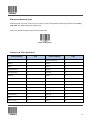
USB Country Keyboard Types
Keyboard layouts and country codes vary from country to country. All supported keyboard types are listed in the Country
Code Table. The default setting is US keyboard type.
To learn how to select a keyboard type, see the example below.
Select Country Code
Country Code Table (Appendix 5)
Country/Language
Code
Country/Language
Code
US
0
Netherlands(Dutch)
14
Belgium
1
Norway
15
Brazil
2
Poland
16
Canada(French)
3
Portugal
17
Czechoslovakia
4
Romania
18
Denmark
5
Russia
19
Finland(Swedish)
6
Slovakia
21
France
7
Spain
22
Germany/Austria
8
Sweden
23
Greece
9
Switzerland(German)
24
Hungary
10
Turkey F
25
Israel(Hebrew)
11
Turkey Q
26
Italy
12
UK
27
Latin-American
13
Japan
28
** Exit Setup
12
Enter Setup
Example: Program the engine to emulate Norwegian keyboard (Norway)
1.
Scan the Enter Setup barcode.
2.
Scan the Select Country Code barcode.
3.
Check the country code for Norway in the Country Code Table. (Norway: 15)
4.
Scan the numeric barcodes “1” and “5”.
5.
Scan the Save barcode.
6.
Scan the Exit Setup barcode.
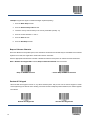
Beep on Unknown Character
Due to the differences in keyboard layouts, some characters contained in barcode data may be unavailable on the selected
keyboard. As a result, the engine fails to transmit the unknown characters.
Scan the appropriate barcode below to enable or disable the emission of beep when an unknown character is detected.
Note: If Emulate ALT+Keypad ON is selected, Beep on Unknown Character does not function.
Beep on Unknown Character
** Do Not Beep on Unknown Character
Emulate ALT+Keypad
When Emulate ALT+Keypad is turned on, any ASCII character (0x00 - 0xff) is sent over the numeric keypad no matter
which keyboard type is selected. Since sending a character involves multiple keystroke emulations, this method appears
less efficient.
Emulate ALT+Keypad ON
13
** Emulate ALT+Keypad OFF
**Exit Setup
Enter Setup
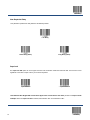
Function Key Mapping
When Function Key Mapping is enabled, function characters (0x00 - 0x1F) are sent as ASCII sequences over the numeric
keypad. For more information, see Appendix 6: ASCII Function Key Mapping Table.
A shortcut to send a function key (F1-F12) is to scan the corresponding barcode in Appendix 9: F-Key Barcodes.
Note: Emulate ALT+Keypad ON prevails over Enable Function Key Mapping.
Enable Function Key Mapping
** Disable Function Key Mapping
Example: Barcode data 0x16
** Exit Setup
Enable Function Key Mapping
Ctrl +V
Disable Function Key Mapping
F1
14
Enter Setup
Inter-Keystroke Delay
This parameter specifies the delay between emulated keystrokes.
** No Delay
Short Delay (20ms)
Long Delay (40ms)
Caps Lock
The Caps Lock ON option can invert upper and lower case characters contained in barcode data. This inversion occurs
regardless of the state of Caps Lock key on the Host’s keyboard.
Caps Lock ON
** Caps Lock OFF
Note: Emulate ALT+Keypad ON/ Convert All to Upper Case/ Convert All to Lower Case prevails over Caps Lock ON.
Example: When the Caps Lock ON is selected, barcode data “AbC” is transmitted as “aBc”.
15
**Exit Setup
Enter Setup
Convert Case
Scan the appropriate barcode below to convert all bar code data to your desired case.
Note: If Emulate ALT+Keypad ON is selected, Convert All to Lower Case and Convert All to Upper Case do not
function.
** No Case Conversion
Convert All to Upper Case
Convert All to Lower Case
Example: When the Convert All to Lower Case feature is enabled, barcode data “AbC” is transmitted as “abc”.
** Exit Setup
16
Enter Setup
Emulate Numeric Keypad
Do Not Emulate Numeric Keypad 1: Sending a number (0-9) is emulated as keystroke(s) on main keyboard.
Emulate Numeric Keypad 1: Sending a number (0-9) is emulated as keystroke(s) on numeric keypad. The state of Num
Lock on the simulated numeric keypad is determined by its equivalent on the Host. If Num Lock on the Host is turned off,
the output of simulated numeric keypad is function key instead of number.
Do Not Emulate Numeric Keypad 2: Sending “+”, “-”, “*” and “/” is emulated as keystroke(s) on main keyboard.
Emulate Numeric Keypad 2: Sending “+”, “-”, “*” and “/” is emulated as keystroke(s) on numeric keypad.
Emulate Numeric Keypad 1
** Do Not Emulate Numeric Keypad 1
Emulate Numeric Keypad 2
** Do Not Emulate Numeric Keypad 2
Note: Emulate ALT+Keypad ON prevails over Emulate Numeric Keypad 1 and Emulate Numeric Keypad 2.
Example: Supposing the Emulate Numeric Keypad 1 feature is enabled:
if Num Lock on the Host is ON, “A4.5” is transmitted as “A4.5”;
if Num Lock on the Host is OFF, “A4.5” is transmitted as follows:
17
1.
“A” is sent as is because it is not included in numeric keypad;
2.
“4” is sent as the function key “Cursor Move to Left”;
3.
“.” is sent as the function key “Delete After the Cursor”;
4.
“5” is not sent as it does not correspond to any function key.
**Exit Setup
Enter Setup
USB COM Port Emulation
If you connect the engine to the Host via a USB connection, the USB COM Port Emulation feature allows the Host to
receive data in the way as a serial port does. However, you need to set communication parameters on the engine to match
the Host requirements.
USB COM Port Emulation
HID-POS
The HID-POS interface is recommended for new application programs. It can send up to 56 characters in a single USB
report and appears more efficient than keyboard emulation.
Features:
HID based, no custom driver required.
Way more efficient in communication than keyboard emulation and traditional RS-232 interface.
Note: HID-POS does not require a custom driver. However, a HID interface on Windows 98 does. All HID interfaces
employ standard driver provided by the operating system. Use defaults when installing the driver.
HID-POS
Access the engine with your program:
1.
Use CreateFile to access the engine as a HID device.
2.
Use ReadFile to deliver the scanned data to the application program.
3.
Use WriteFile to send data to the engine.
For detailed information about USB and HID interfaces, go to www.USB.org.
** Exit Setup
18
Enter Setup
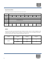
Acquire Scanned Data
After a barcode is decoded, the engine sends an input report as below:
Bit
Byte
7
6
5
0
Report ID = 0x02
1
Barcode Length
4
2-57
Decoded Data (1-56)
58-61
Reserved (1-4)
3
2
1
-
-
0
Symbology ID Number (Appendix 7) or N/C: 0x00
62
63
-
-
-
-
-
Decoded Data
Continued
VID/PID
USB uses VID (Vendor ID) and PID (Product ID) to identify and locate a device. The VID is assigned by USB
Implementers Forum. Newland’s vendor ID is 1EAB (Hex). A range of PIDs are used for each Newland product family.
Every PID contains a base number and interface type (keyboard, COM port, etc.).
Product
Interface
PID (Hex)
PID (Dec)
Base
0000
0
HID-POS
0010
16
EM2037
19
**Exit Setup
Enter Setup
IBM SurePOS(Tabletop)
IBM-SurePOS (Table-Top)
IBM SurePOS (Handheld)
IBM-SurePOS (Hand-Held)
** Exit Setup
20
Enter Setup
Chapter 3 Scan Mode
Trigger Mode
If the Trigger Mode is enabled, receiving an active trigger signal activates a decode session. The session continues until the
barcode is decoded or the active signal is not present. For good decode, the engine transmits decoded data via
communication port. To activate another session, the Host needs to first terminate the trigger signal, wait 20ms or longer and
then send an active signal.
Trigger Mode
Auto Mode
If the Auto Mode is enabled, the engine activates a decode session every time it detects a change in ambient illumination.
The decode session continues until the barcode is decoded or the Decode Session Timeout expires.
Receiving a trigger signal can also activate a decode session. The decode session continues until the trigger signal
becomes invalid or the barcode is decoded or the Decode Session Timeout expires. The trigger signal needs to be
terminated before the engine is able to monitor ambient illumination again.
** Auto Mode
21
**Exit Setup
Enter Setup
Decode Session Timeout
This parameter sets the maximum time decode session continues during a scan attempt in the Auto Mode. It is
programmable in 1ms increments from 500ms to 3600000ms. The default timeout is 3000ms. To learn how to program this
parameter, see the “a. Program the Decode Session Timeout” section in Appendix 8.
Decode Session Timeout
** Exit Setup
22
Enter Setup
Timeout between Decodes (Same Barcode)
Timeout between Decodes (Same Barcode) can avoid undesired rereading of same barcode in a given period of time.
This parameter sets the timeout between decodes for same barcode in the Auto Mode. It is programmable in 1ms
increments from 0ms to 3600000ms. The default timeout is 1500ms.
To learn how to program this parameter, see the “b. Program the Timeout between Decodes (Same Barcode)” section
in Appendix 8.
Timeout between Decodes (Same Barcode)
Disable Timeout between Decodes: Allow the engine to re-read same barcode.
Enable Timeout between Decodes: Do not allow the engine to re-read same barcode before the Timeout between
Decodes (Same Barcode) expires.
** Disable Timeout between Decodes
23
Enable Timeout between Decodes
**Exit Setup
Enter Setup
Continuous Mode
This mode enables the engine to scan/capture, decode and transmit over and over again.
If the Continuous Mode is enabled, the engine activates/suspends/resumes barcode reading through control over the
trigger signal. When barcode reading is in progress, terminating the trigger signal after having kept it valid for 30ms or
longer will suspend barcode reading; when barcode reading is suspended, performing the same control over the trigger
signal will resume barcode reading.
Continuous Mode
** Exit Setup
24
Enter Setup
Timeout between Decodes (Same Barcode)
Timeout between Decodes (Same Barcode) can avoid undesired rereading of same barcode in a given period of time.
This parameter sets the timeout between decodes for same barcode in the Continuous Mode. It is programmable in 1ms
increments from 0ms to 3600000ms. The default timeout is 1500ms.
To learn how to program this parameter, see the “b. Program the Timeout between Decodes (Same Barcode)” section
in Appendix 8.
Timeout Between Decodes (Same Barcode)
Disable Timeout between Decodes: Allow the engine to re-read same barcode.
Enable Timeout between Decodes: Do not allow the engine to re-read same barcode before the Timeout between
Decodes (Same Barcode) expires.
** Disable Timeout between Decodes
25
Enable Timeout between Decodes
**Exit Setup
Enter Setup
Chapter 4 Scanning Preferences
Introduction
This chapter contains information as to how to adapt your engine to various applications with preference setting. For
instance, to improve barcode reading performance off mobile phones and LCD displays; or to narrow the field of view of the
engine to make sure it reads only those barcodes intended by the user.
Regular Mode/Mobile Phone Mode
The engine can capture barcodes printed on paper labels or displayed on the screen of a mobile phone. Select a mode as
per actual need.
Regular Mode: Read barcodes printed on paper or plastic.
Mobile Phone Mode: Read barcodes off mobile phones or LCD displays.
** Regular Mode
Mobile Phone Mode
Decode Area
Whole Area Decoding
When this option is enabled, the engine attempts to decode barcode(s) within its field of view, from the center to the
periphery, and transmits the barcode that has been first decoded.
** Whole Area Decoding
** Exit Setup
26
Enter Setup
Central Area Decoding
The engine attempts to decode barcode(s) within a specified central area and transmits the barcode that has been first
decoded. This option allows the engine to narrow its field of view to make sure it reads only those barcodes intended by the
user. For instance, if multiple barcodes are placed closely together, central area decoding in conjunction with appropriate
pre-defined central area will insure that only the desired barcode is read.
Central Area Decoding
27
**Exit Setup
Enter Setup
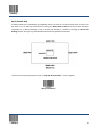
Specify Central Area
The default central area is a (Width*20%) by (Height*20%) area in the center of the engine’s field of view, as shown in the
figure below. You can define the central area by scanning the Specify Central Area barcode and numeric barcode(s)
corresponding to a desired percentage (1-100). If Central Area Decoding is enabled by scanning the Central Area
Decoding barcode, the engine only reads barcodes that intersect the predefined central area.
To learn how to program this parameter, see the “c. Program the Central Area” section in Appendix.
Specify Central Area
** Exit Setup
28
Enter Setup
Chapter 5 Illumination & Aiming
Illumination
A couple of illumination options are provided to improve the lighting conditions during every image capture:
Normal: Illumination LEDs are turned on during image capture.
Always ON: Illumination LEDs keep ON after the engine is powered on.
OFF: Illumination LEDs are OFF all the time.
** Normal
Always ON
OFF
29
**Exit Setup
Enter Setup
Aiming
When scanning/capturing image, the engine projects an aiming pattern which allows positioning the target barcode within its
field of view and thus makes decoding easier.
Normal: The engine projects an aiming pattern only during barcode scanning/capture.
Always ON: Aiming pattern is constantly ON after the engine is powered on.
OFF: Aiming pattern is OFF all the time.
** Normal
Always ON
OFF
** Exit Setup
30
Enter Setup
Chapter 6 Beep & LED Indications
Introduction
Besides communication output, the engine can also generate a PWM signal and a pulse signal. Those outputs in conjunction
with external circuits are able to drive the beeper/LED indicator.
This chapter describes how to program the beep/LED notification feature.
Startup Beep
If startup beep is enabled, the engine will beep after being turned on.
** Enable Startup Beep
Disable Startup Beep
Good Read Beep
The engine can be configured to beep after good decode. Beep type (frequency) and volume (duty circle of PWM) are also
user programmable.
** Good Read Beep On
31
Good Read Beep Off
**Exit Setup
Enter Setup
Beep Type
** Type 1
Type 2
Type 3
Beep Volume
** Loud
Low
Medium
** Exit Setup
32
Enter Setup
Additional Settings for Type 1
Beep duration and frequency settings are designed only for Type 1 (which is a single tone) to serve specific applications.
Beep Duration
** 80ms
40ms
To learn how to program the parameter, see the “d. Program the Duration of Good Decode Beep (Type 1)” section in
Appendix.
Custom (20~300ms)
33
**Exit Setup
Enter Setup
Beep Frequency
800Hz
1600Hz
** 2730Hz
4200Hz
You may select the frequency same as the center frequency of your buzzer. To learn how to program this parameter, see the
“e. Program the Frequency of Good Decode Beep (Type 1)” section in Appendix.
Custom (20~20000 Hz)
** Exit Setup
34
Enter Setup
LED Notification
Good Read LED Notification
Note: This feature is applicable to all scan modes.
Good Read LED Notification Off
** Good Read LED Notification On
LED Notification Duration for Good Read
** Short (20ms)
Medium (120ms)
Long (220ms)
Prolonged (320ms)
To learn how to program this parameter, see the “f. Program the LED Notification Duration for Good Decode” section in
Appendix.
Custom (1~10000ms)
35
**Exit Setup
Enter Setup
Power LED
This feature allows you to turn the Power LED on or off. When the Power LED On barcode is scanned, the power LED is
turned on after the engine is powered up.
Power LED On
** Exit Setup
** Power LED Off
36
Enter Setup
Chapter 7 Data Formatting
Introduction
In many applications, barcode data needs to be edited and distinguished from one another.
Usually AIM ID and Code ID can be used as identifiers, but in some special cases customized prefix and terminating
character suffix like Carriage Return or Line Feed can also be the alternatives.
Data editing refers to appending prefix/suffix, data packing, etc.
Data formatting may include:
37
Append AIM ID/Code ID/custom prefix before the decoded data
Append custom suffix after the decoded data
Pack data
Append terminating character to the end of the data
**Exit Setup
Enter Setup
General Settings
Enable/Disable All Prefix/Suffix
Disable All Prefix/Suffix: Transmit barcode data with no prefix/suffix.
Enable All Prefix/Suffix: Allow user to append Code ID prefix, AIM ID prefix, custom prefix/suffix and terminating character
to the barcode data before the transmission.
Enable All Prefix/Suffix
** Disable All Prefix/Suffix
Prefix Sequences
**Code ID+Custom Prefix+AIM ID
** Exit Setup
Custom Prefix+Code ID+AIM ID
38
Enter Setup
AIM ID Prefix
AIM (Automatic Identification Manufacturers) IDs and ISO/IEC 15424 standards define symbology identifiers and data
carrier identifiers. (For the details, see the “Appendix 2: AIM ID Table” section). If AIM ID prefix is enabled, the engine will
add the symbology identifier before the scanned data after decoding.
Enable AIM ID Prefix
** Disable AIM ID Prefix
Code ID Prefix
Code ID can also be used to identify barcode type. Unlike AIM ID, Code ID is user programmable. Code ID can only consist
of one or two English letters.
Enable Code ID Prefix
39
** Disable Code ID Prefix
**Exit Setup
Enter Setup
Restore All Default Code IDs
For the information of default Code IDs, see the “Appendix 3: Code ID Table” section.
Restore All Default Code IDs
Modify Code ID
Code ID of each symbology can be programmed separately. See the following example to learn how to program a Code ID.
Example: Set the Code ID of PDF417 to “p”
1.
Check the hex value of “p” in the Appendix 4: ASCII Table. (“p”: 70)
2.
Scan the Enter Setup barcode.
3.
Scan the Modify PDF417 Code ID barcode.
4.
Scan the numeric barcodes “7” and “0”.
5.
Scan the Save barcode.
6.
Scan the Exit Setup barcode.
** Exit Setup
40
Enter Setup
41
Modify PDF417 Code ID
Modify Data Matrix Code ID
Modify QR Code ID
Modify Maxicode Code ID
Modify Aztec Code ID
Modify Chinese Sensible Code ID
Modify EAN-8 Code ID
Modify EAN-13 Code ID
Modify UPC-E Code ID
Modify UPC-A Code ID
**Exit Setup
Enter Setup
Modify Code 128 Code ID
Modify UCC/EAN-128 Code ID
Modify Code 39 Code ID
Modify Code 93 Code ID
Modify Interleaved 2 of 5 Code ID
Modify ITF-14 Code ID
Modify ITF-6 Code ID
Modify Codabar Code ID
Modify Industrial 25 Code ID
Modify Standard 25 Code ID
** Exit Setup
42
Enter Setup
Modify Code 11 Code ID
Modify Plessey Code ID
Modify MSI-Plessey Code ID
Modify GS1 Databar Code ID
Modify Composite Code ID
Modify ISBN Code ID
Modify Matrix 2 of 5 Code ID
Modify ISSN Code ID
Modify Micro PDF417 Code ID
43
**Exit Setup
Enter Setup
Custom Prefix
Enable/Disable Custom Prefix
If custom prefix is enabled, you are allowed to append to the data a user-defined prefix that cannot exceed 10 characters.
Enable Custom Prefix
** Disable Custom Prefix
Set Custom Prefix
To set a custom prefix, scan the Set Custom Prefix barcode and the numeric barcodes corresponding to the hexadecimal
value of a desired prefix, and then scan the Save barcode.
Note: A custom prefix cannot exceed 10 characters.
Set Custom Prefix
Example: Set the custom prefix to “CODE”
1.
Check the hex values of “CODE” in the ASCII Table. (“CODE”: 43, 4F, 44, 45)
2.
Scan the Enter Setup barcode.
3.
Scan the Set Custom Prefix barcode.
4.
Scan the numeric barcodes “4”, “3”, “4”, “F”, “4”, “4”, “4” and “5”.
5.
Scan the Save barcode.
6.
Scan the Exit Setup barcode.
** Exit Setup
44
Enter Setup
Custom Suffix
Enable/Disable Custom Suffix
If custom suffix is enabled, you are allowed to append to the data a user-defined suffix that cannot exceed 10 characters.
Enable Custom Suffix
** Disable Custom Suffix
Set Custom Suffix
To set a custom suffix, scan the Set Custom Suffix barcode and the numeric barcodes corresponding to the hexadecimal
value of a desired suffix, and then scan the Save barcode.
Note: A custom suffix cannot exceed 10 characters.
Set Custom Suffix
Example: Set the custom suffix to “CODE”
45
1.
Check the hex values of “CODE” in the ASCII Table. (“CODE”: 43, 4F, 44, 45)
2.
Scan the Enter Setup barcode.
3.
Scan the Set Custom Suffix barcode.
4.
Scan the numeric barcodes “4”, “3”, “4”, “F”, “4”, “4”, “4” and “5”.
5.
Scan the Save barcode.
6.
Scan the Exit Setup barcode.
**Exit Setup
Enter Setup
Data Packing
For some applications that require high data integrity and reliability, data packing can help you accomplish that.
Transmission of packed data needs to work with certain software on the Host.
Data packing influences data format and is not recommended for general applications.
** Disable Data Packing
Normal Pack
Normal Pack format: [STX + ATTR + LEN] + [AL_TYPE + DATA] + [LRC]
STX: 0x02
ATTR: 0x00
LEN: Barcode data length is expressed in 2 bytes, ranging from 0 to 65535.
AL_TYPE: 0x36
DATA: Raw barcode data.
LRC: Checksum.
LRC calculation algorithm: computation sequence: 0xFF+LEN+AL_TYPE+DATA; computation method is XOR, byte by
byte.
Normal Pack
** Exit Setup
46
Enter Setup
Terminating Character Suffix
A terminating character can be used to mark the end of data, which means nothing can be added after it.
A terminating character suffix can contain one or two characters.
Enable/Disable Terminating Character Suffix
To enable/disable terminating character suffix, scan the appropriate barcode below.
Enable Terminating Character Suffix
47
** Disable Terminating Character Suffix
**Exit Setup
Enter Setup
Set Terminating Character Suffix
The engine provides a shortcut for setting the terminating character suffix to 0x0D (CR) or 0x0D,0x0A (CRLF) by scanning
the following barcode.
Terminating Character 0x0D
Terminating Character 0x0D,0x0A
To set a terminating character suffix, scan the Set Terminating Character Suffix barcode and the numeric barcodes
corresponding to the hexadecimal value of a desired terminating character, and then scan the Save barcode.
Note: A terminating character suffix cannot exceed 2 characters.
Set Terminating Character Suffix
Example: Set the terminating character suffix to 0x0D
1.
Scan the Enter Setup barcode.
2.
Scan the Set Terminating Character Suffix barcode.
3.
Scan the numeric barcodes “0” and “D”.
4.
Scan the Save barcode.
5.
Scan the Exit Setup barcode.
** Exit Setup
48
Enter Setup
Chapter 8 Symbologies
General Settings
Enable/Disable All Symbologies
If the Disable All Symbologies feature is enabled, the engine can only identify the programming barcodes.
Enable All Symbologies
Disable All Symbologies
Enable/Disable 1D Symbologies
Enable 1D Symbologies
Disable 1D Symbologies
Enable/Disable 2D Symbologies
Enable 2D Symbologies
49
Disable 2D Symbologies
**Exit Setup
Enter Setup
1D Symbologies
Code 128
Restore Factory Defaults
Restore the Factory Defaults of Code 128
Enable/Disable Code 128
** Enable Code 128
Disable Code 128
Set Length Range for Code 128
The engine can be configured to only decode Code 128 barcodes with lengths that fall between (inclusive) the minimum
and maximum lengths. To accomplish it, you need to set the minimum and maximum lengths.
For more information, see the “j. Program the Length Range (Maximum/Mininum Lengths) for a Symbology” section
in Appendix.
Set the Minimum Length (Default: 1)
** Exit Setup
Set the Maximum Length (Default: 48)
50
Enter Setup
GS1-128 (UCC/EAN-128)
Restore Factory Defaults
Restore the Factory Defaults of GS1-128
Enable/Disable GS1-128
** Enable GS1-128
Disable GS1-128
Set Length Range for GS1-128
The engine can be configured to only decode GS1-128 barcodes with lengths that fall between (inclusive) the minimum
and maximum lengths. To accomplish it, you need to set the minimum and maximum lengths.
For more information, see the “j. Program the Length Range (Maximum/Mininum Lengths) for a Symbology” section
in Appendix.
Set the Minimum Length (Default: 1)
51
Set the Maximum Length (Default: 48)
**Exit Setup
Enter Setup
EAN-8
Restore Factory Defaults
Restore the Factory Defaults of EAN-8
Enable/Disable EAN-8
** Enable EAN-8
Disable EAN-8
Transmit Check Digit
EAN-8 is 8 digits in length with the last one as its check digit used to verify the integrity of the data.
** Transmit EAN-8 Check Digit
** Exit Setup
Do Not Transmit EAN-8 Check Digit
52
Enter Setup
Add-On Code
An EAN-8 barcode can be augmented with a two-digit or five-digit add-on code to form a new one. In the examples below,
the part surrounded by blue dotted line is an EAN-8 barcode while the part circled by red dotted line is add-on code.
Enable 2-Digit Add-On Code
** Disable 2-Digit Add-On Code
Enable 5-Digit Add-On Code
** Disable 5-Digit Add-On Code
Enable 2-Digit Add-On Code/ Enable 5-Digit Add-On Code: The engine decodes a mix of EAN-8 barcodes with and
without 2-digit/5-digit add-on codes.
Disable 2-Digit Add-On Code/ Disable 5-Digit Add-On Code: The engine decodes EAN-8 and ignores the add-on code
when presented with an EAN-8 plus add-on barcode. It can also decode EAN-8 barcodes without add-on codes.
53
**Exit Setup
Enter Setup
EAN-8 Extension
Disable EAN-8 Zero Extend: Transmit EAN-8 barcodes as is.
Enable EAN-8 Zero Extend: Add five leading zeros to decoded EAN-8 barcodes to extend to13 digits.
Enable EAN-8 Zero Extend
** Exit Setup
** Disable EAN-8 Zero Extend
54
Enter Setup
EAN-13
Restore Factory Defaults
Restore the Factory Defaults of EAN-13
Enable/Disable EAN-13
** Enable EAN-13
Disable EAN-13
Transmit Check Digit
** Transmit EAN-13 Check Digit
55
Do Not Transmit EAN-13 Check Digit
**Exit Setup
Enter Setup
Add-On Code
An EAN-13 barcode can be augmented with a two-digit or five-digit add-on code to form a new one.
Enable 2-Digit Add-On Code
** Disable 2-Digit Add-On Code
Enable 5-Digit Add-On Code
** Disable 5-Digit Add-On Code
Enable 2-Digit Add-On Code/ Enable 5-Digit Add-On Code: The engine decodes a mix of EAN-13 barcodes with and
without 2-digit/5-digit add-on codes.
Disable 2-Digit Add-On Code/ Disable 5-Digit Add-On Code: The engine decodes EAN-13 and ignores the add-on code
when presented with an EAN-13 plus add-on barcode. It can also decode EAN-13 barcodes without add-on codes.
** Exit Setup
56
Enter Setup
ISBN
Restore Factory Defaults
Restore the Factory Defaults of ISBN
Enable/Disable ISBN
Enable ISBN
** Disable ISBN
Set ISBN Format
**ISBN-13
57
ISBN-10
**Exit Setup
Enter Setup
UPC-E
Restore Factory Defaults
Restore the Factory Defaults of UPC-E
Enable/Disable UPC-E
** Enable UPC-E
Disable UPC-E
Transmit Check Digit
** Transmit UPC-E Check Digit
** Exit Setup
Do Not Transmit UPC-E Check Digit
58
Enter Setup
Add-On Code
A UPC-E barcode can be augmented with a two-digit or five-digit add-on code to form a new one.
Enable 2-Digit Add-On Code
** Disable 2-Digit Add-On Code
Enable 5-Digit Add-On Code
** Disable 5-Digit Add-On Code
Enable 2-Digit Add-On Code/ Enable 5-Digit Add-On Code: The engine decodes a mix of UPC-E barcodes with and
without 2-digit/5-digit add-on codes.
Disable 2-Digit Add-On Code/ Disable 5-Digit Add-On Code: The engine decodes UPC-E and ignores the add-on code
when presented with a UPC-E plus add-on barcode. It can also decode UPC-E barcodes without add-on codes.
59
**Exit Setup
Enter Setup
UPC-E Preamble
Preamble characters (Country Code and System Character) can be transmitted as part of a UPC-E barcode. Select one of
the following options for transmitting UPC-E preamble to the host device: transmit system character only, transmit system
character and country code (“0” for USA), or transmit no preamble.
** No Preamble (<DATA>)
System Character (<SYSTEM CHARACTER><DATA>)
System Character & Country Code(< COUNTRY
CODE><SYSTEM CHARACTER><DATA>)
Convert UPC-E to UPC-A
Do Not Convert UPC-E to UPC-A: Transmit UPC-E barcodes as is.
Convert UPC-E to UPC-A: Enable this to convert UPC-E decoded data to UPC-A format before transmission. After
conversion, the data follows UPC-A format and is affected by UPC-A programming selections (e.g., Preamble, Check
Digit)..
** Do Not Convert UPC-E to UPC-A
** Exit Setup
Convert UPC-E to UPC-A
60
Enter Setup
UPC-A
Restore Factory Defaults
Restore the Factory Defaults of UPC-A
Enable/Disable UPC-A
** Enable UPC-A
Disable UPC-A
Transmit Check Digit
** Transmit UPC-A Check Digit
61
Do Not Transmit UPC-A Check Digit
**Exit Setup
Enter Setup
Add-On Code
A UPC-A barcode can be augmented with a two-digit or five-digit add-on code to form a new one.
Enable 2-Digit Add-On Code
** Disable 2-Digit Add-On Code
Enable 5-Digit Add-On Code
** Disable 5-Digit Add-On Code
Enable 2-Digit Add-On Code/ Enable 5-Digit Add-On Code: The engine decodes a mix of UPC-A barcodes with and
without 2-digit/5-digit add-on codes.
Disable 2-Digit Add-On Code/ Disable 5-Digit Add-On Code: The engine decodes UPC-A and ignores the add-on code
when presented with a UPC-A plus add-on barcode. It can also decode UPC-A barcodes without add-on codes.
** Exit Setup
62
Enter Setup
UPC-A Preamble
Preamble characters (Country Code and System Character) can be transmitted as part of a UPC-A barcode. Select one of
the following options for transmitting UPC-A preamble to the host device: transmit system character only, transmit system
character and country code (“0” for USA), or transmit no preamble.
No Preamble (<DATA>)
** System Character (<SYSTEM CHARACTER><DATA>)
System Character & Country Code(< COUNTRY
CODE><SYSTEM CHARACTER><DATA>)
63
**Exit Setup
Enter Setup
Interleaved 2 of 5
Restore Factory Defaults
Restore the Factory Defaults of Interleaved 2 of 5
Enable/Disable Interleaved 2 of 5
** Enable Interleaved 2 of 5
Disable Interleaved 2 of 5
Set Length Range for Interleaved 2 of 5
The engine can be configured to only decode Interleaved 2 of 5 barcodes with lengths that fall between (inclusive) the
minimum and maximum lengths. To accomplish it, you need to set the minimum and maximum lengths.
For more information, see the “j. Program the Length Range (Maximum/Mininum Lengths) for a Symbology” section
in Appendix.
Set the Minimum Length (Default: 6)
** Exit Setup
Set the Maximum Length (Default: 80)
64
Enter Setup
Check Digit Verification
A check digit is optional for Interleaved 2 o 5 and can be added as the last digit. It is a calculated value used to verify the
integrity of the data.
Disable: The engine transmits Interleaved 2 of 5 barcodes as is.
Do Not Transmit Check Digit After Verification: The engine checks the integrity of all Interleaved 2 of 5 barcodes to
verify that the data complies with the check digit algorithm. Barcodes passing the check will be transmitted except the last
digit, whereas those failing it will not be transmitted.
Transmit Check Digit After Verification: The engine checks the integrity of all Interleaved 2 of 5 barcodes to verify that
the data complies with the check digit algorithm. Barcodes passing the check will be transmitted, whereas those failing it
will not be transmitted.
** Disable
Do Not Transmit Check Digit After Verification
Transmit Check Digit After Verification
Note: If the Do Not Transmit Check Digit After Verification option is enabled, Interleaved 2 of 5 barcodes with a length
that is less than the configured minimum length after having the check digit excluded will not be decoded. (For example,
when the Do Not Transmit Check Digit After Verification option is enabled and the minimum length is set to 4,
Interleaved 2 of 5 barcodes with a total length of 4 characters including the check digit cannot be read.)
65
**Exit Setup
Enter Setup
Set Discrete Lengths for Interleaved 2 of 5
The engine can be configured to only decode Interleaved 2 of 5 barcodes within a specific length range or with a couple of
discrete lengths.
The length must be an even number not greater than 64 and consist of three digits (a leading zero or zeros may need to
be added to meet the length requirement). For more information, see the “k. Program the Discrete Lengths for
Interleaved 2 of 5” section in Appendix.
Enable the Discrete Lengths
** Disable the Discrete Lengths
The discrete lengths become valid only when the Enable the Discrete Lengths option is enabled.
Set the Discrete Length
** Exit Setup
Delete the Discrete Length
66
Enter Setup
ITF-14
ITF-14 is a special kind of Interleaved 2 of 5 with a length of 14 characters and the last character as the check character.
** Disable ITF-14
Enable ITF-14 But Do Not Transmit Check Digit
Enable ITF-14 and Transmit Check Digit
Note: It is advisable not to enable ITF-14 and Interleaved 2 of 5 at the same time.
67
**Exit Setup
Enter Setup
ITF-6
ITF-6 is a special kind of Interleaved 2 of 5 with a length of 6 characters and the last character as the check character.
** Disable ITF-6
Enable ITF-6 But Do Not Transmit Check Digit
Enable ITF-6 and Transmit Check Digit
Note: It is advisable not to enable ITF-6 and Interleaved 2 of 5 at the same time.
** Exit Setup
68
Enter Setup
Matrix 2 of 5
Restore Factory Defaults
Restore the Factory Defaults of Matrix 2 of 5
Enable/Disable Matrix 2 of 5
Enable Matrix 2 of 5
** Disable Matrix 2 of 5
Set Length Range for Matrix 2 of 5
The engine can be configured to only decode Matrix 2 of 5 barcodes with lengths that fall between (inclusive) the minimum
and maximum lengths. To accomplish it, you need to set the minimum and maximum lengths.
For more information, see the “j. Program the Length Range (Maximum/Mininum Lengths) for a Symbology” section
in Appendix.
Set the Minimum Length (Default: 4)
69
Set the Maximum Length (Default: 80)
**Exit Setup
Enter Setup
Check Digit Verification
A check digit is optional for Matrix 2 of 5 and can be added as the last digit. It is a calculated value used to verify the
integrity of the data.
Disable: The engine transmits Matrix 2 of 5 barcodes as is.
Do Not Transmit Check Digit After Verification: The engine checks the integrity of all Matrix 2 of 5 barcodes to verify that
the data complies with the check digit algorithm. Barcodes passing the check will be transmitted except the last digit,
whereas those failing it will not be transmitted.
Transmit Check Digit After Verification: The engine checks the integrity of all Matrix 2 of 5 barcodes to verify that the
data complies with the check digit algorithm. Barcodes passing the check will be transmitted, whereas those failing it will
not be transmitted.
** Disable
Do Not Transmit Check Digit After Verification
** Exit Setup
Transmit Check Digit After Verification
70
Enter Setup
Code 39
Restore Factory Defaults
Restore the Factory Defaults of Code 39
Enable/Disable Code 39
** Enable Code 39
Disable Code 39
Set Length Range for Code 39
The engine can be configured to only decode Code 39 barcodes with lengths that fall between (inclusive) the minimum
and maximum lengths. To accomplish it, you need to set the minimum and maximum lengths.
For more information, see the “j. Program the Length Range (Maximum/Mininum Lengths) for a Symbology” section
in Appendix.
Set the Minimum Length (Default: 4)
71
Set the Maximum Length (Default: 48)
**Exit Setup
Enter Setup
Check Digit Verification
A check digit is optional for Code 39 and can be added as the last digit. It is a calculated value used to verify the integrity of
the data.
Disable: The engine transmits Code 39 barcodes as is.
Do Not Transmit Check Digit After Verification: The engine checks the integrity of all Code 39 barcodes to verify that the
data complies with the check digit algorithm. Barcodes passing the check will be transmitted except the last digit, whereas
those failing it will not be transmitted.
Transmit Check Digit After Verification: The engine checks the integrity of all Code 39 barcodes to verify that the data
complies with the check digit algorithm. Barcodes passing the check will be transmitted, whereas those failing it will not be
transmitted.
** Disable
Do Not Transmit Check Digit After Verification
** Exit Setup
Transmit Check Digit After Verification
72
Enter Setup
Transmit Start/Stop Character
** Transmit Start/Stop Character
Do Not Transmit Start/Stop Character
Enable/Disable Code 39 Full ASCII
By default, the engine is only able to read some ASCII characters. You can configure your engine to identify all ASCII
characters by scanning the appropriate barcode below.
Enable Code 39 Full ASCII
73
** Disable Code 39 Full ASCII
**Exit Setup
Enter Setup
Convert Code 39 to Code 32
Code 32 is a variant of Code 39 used by the Italian pharmaceutical industry. Scan the appropriate barcode below to enable
or disable converting Code 39 to Code 32. Code 39 must be enabled and Code 39 check digit verification must be disabled
for this parameter to function.
** Disable Convert Code 39 to Code 32
Enable Convert Code 39 to Code 32
Code 32 Prefix
Scan the appropriate barcode below to enable or disable adding the prefix character “A” to all Code 32 bar codes. Convert Code 39 to Code 32 must be enabled for this parameter to function.
** Disable Code 32 Prefix
** Exit Setup
Enable Code 32 Prefix
74
Enter Setup
Codabar
Restore Factory Defaults
Restore the Factory Defaults of Codabar
Enable/Disable Codabar
** Enable Codabar
Disable Codabar
Set Length Range for Codabar
The engine can be configured to only decode Codabar barcodes with lengths that fall between (inclusive) the minimum
and maximum lengths. To accomplish it, you need to set the minimum and maximum lengths.
For more information, see the “j. Program the Length Range (Maximum/Mininum Lengths) for a Symbology” section
in Appendix.
Set the Minimum Length (Default: 2)
75
Set the Maximum Length (Default: 60)
**Exit Setup
Enter Setup
Check Digit Verification
A check digit is optional for Codabar and can be added as the last digit. It is a calculated value used to verify the integrity of
the data.
Disable: The engine transmits Codabar barcodes as is.
Do Not Transmit Check Digit After Verification: The engine checks the integrity of all Codabar barcodes to verify that the
data complies with the check digit algorithm. Barcodes passing the check will be transmitted except the last digit, whereas
those failing it will not be transmitted.
Transmit Check Digit After Verification: The engine checks the integrity of all Codabar barcodes to verify that the data
complies with the check digit algorithm. Barcodes passing the check will be transmitted, whereas those failing it will not be
transmitted.
** Disable
Do Not Transmit Check Digit After Verification
** Exit Setup
Transmit Check Digit After Verification
76
Enter Setup
Transmit Start/Stop Character
** Transmit Start/Stop Character
Do Not Transmit Start/Stop Character
Start/Stop Character Format
You can choose your desired start/stop characters format by scanning the appropriate barcode below.
77
** ABCD/ABCD as the Start/Stop Character
ABCD/TN*E as the Start/Stop Character
** Start/Stop Character in Uppercase
Start/Stop Character in Lowercase
**Exit Setup
Enter Setup
Code 93
Restore Factory Defaults
Restore the Factory Defaults of Code 93
Enable/Disable Code 93
Enable Code 93
** Disable Code 93
Set Length Range for Code 93
The engine can be configured to only decode Code 93 barcodes with lengths that fall between (inclusive) the minimum
and maximum lengths. To accomplish it, you need to set the minimum and maximum lengths.
For more information, see the “j. Program the Length Range (Maximum/Mininum Lengths) for a Symbology” section
in Appendix.
Set the Minimum Length (Default: 1)
** Exit Setup
Set the Maximum Length (Default: 48)
78
Enter Setup
Check Digit Verification
Check digits are optional for Code 93 and can be added as the last two digits, which are calculated values used to verify
the integrity of the data.
Disable: The engine transmits Code 93 barcodes as is.
Do Not Transmit Check Digit After Verification: The engine checks the integrity of all Code 93 barcodes to verify that the
data complies with the check digit algorithm. Barcodes passing the checks will be transmitted except the last two digits,
whereas those failing them will not be transmitted.
Transmit Check Digit After Verification: The engine checks the integrity of all Code 93 barcodes to verify that the data
complies with the check digit algorithm. Barcodes passing the checks will be transmitted, whereas those failing them will
not be transmitted.
Disable
** Do Not Transmit Check Digit After Verification
79
Transmit Check Digit After Verification
**Exit Setup
Enter Setup
GS1-Databar (RSS)
Restore Factory Defaults
Restore the Factory Defaults of GS1-Databar
Enable/Disable GS1 Databar
** Enable GS1-DataBar
Disable GS1-DataBar
Transmit Application Identifier “01”
** Transmit Application Identifier “01”
** Exit Setup
Do Not Transmit Application Identifier “01”
80
Enter Setup
GS1 Composite Code
Restore Factory Defaults
Restore the Factory Defaults of GS1 Composite Code
Enable/Disable GS1 Composite Code
Enable GS1 Composite Code
** Disable GS1 Composite Code
EAN/UPC Composite
When EAN/UPC Composite is enabled, the engine will not be able to read standard EAN/UPC barcodes.
Enable EAN/UPC Composite
81
** Disable EAN/UPC Composite
**Exit Setup
Enter Setup
Code 11
Restore Factory Defaults
Restore the Factory Defaults of Code 11
Enable/Disable Code 11
Enable Code 11
** Disable Code 11
Set Length Range for Code 11
The engine can be configured to only decode Code 11 barcodes with lengths that fall between (inclusive) the minimum
and maximum lengths. To accomplish it, you need to set the minimum and maximum lengths.
For more information, see the “j. Program the Length Range (Maximum/Mininum Lengths) for a Symbology” section
in Appendix.
Set the Minimum Length (Default: 4)
** Exit Setup
Set the Maximum Length (Default: 48)
82
Enter Setup
Transmit Check Digit
** Transmit Check Digit
Do Not Transmit Check Digit
Check Digit Verification
83
Disable
** One Check Digit, MOD11
Two Check Digits, MOD11/MOD11
Two Check Digits, MOD11/MOD9
One Check Digit, MOD11 (Len<=10)
One Check Digit, MOD11 (Len<=10)
Two Check Digits, MOD11/MOD11 (Len>10)
Two Check Digits, MOD11/MOD9 (Len>10)
**Exit Setup
Enter Setup
Industrial 2 of 5
Restore Factory Defaults
Restore the Factory Defaults of Industrial 2 of 5
Enable/Disable Industrial 2 of 5
Enable Industrial 2 of 5
** Disable Industrial 2 of 5
Set Length Range for Industrial 2 of 5
The engine can be configured to only decode Industrial 2 of 5 barcodes with lengths that fall between (inclusive) the
minimum and maximum lengths. To accomplish it, you need to set the minimum and maximum lengths.
For more information, see the “j. Program the Length Range (Maximum/Mininum Lengths) for a Symbology” section
in Appendix.
Set the Minimum Length (Default: 6)
** Exit Setup
Set the Maximum Length (Default: 48)
84
Enter Setup
Check Digit Verification
A check digit is optional for Industrial 2 of 5 and can be added as the last digit. It is a calculated value used to verify the
integrity of the data.
Disable: The engine transmits Industrial 2 of 5 barcodes as is.
Do Not Transmit Check Digit After Verification: The engine checks the integrity of all Industrial 2 of 5 barcodes to verify
that the data complies with the check digit algorithm. Barcodes passing the check will be transmitted except the last digit,
whereas those failing it will not be transmitted.
Transmit Check Digit After Verification: The engine checks the integrity of all Industrial 2 of 5 barcodes to verify that the
data complies with the check digit algorithm. Barcodes passing the check will be transmitted, whereas those failing it will
not be transmitted.
** Disable
Do Not Transmit Check Digit After Verification
85
Transmit Check Digit After Verification
**Exit Setup
Enter Setup
Standard 25
Restore Factory Defaults
Restore the Factory Defaults of Standard 25
Enable/Disable Standard 25
Enable Standard 25
** Disable Standard 25
Set Length Range for Standard 25
The engine can be configured to only decode Standard 25 barcodes with lengths that fall between (inclusive) the minimum
and maximum lengths. To accomplish it, you need to set the minimum and maximum lengths.
For more information, see the “j. Program the Length Range (Maximum/Mininum Lengths) for a Symbology” section
in Appendix.
Set the Minimum Length (Default: 6)
** Exit Setup
Set the Maximum Length (Default: 48)
86
Enter Setup
Check Digit Verification
A check digit is optional for Standard 25 and can be added as the last digit. It is a calculated value used to verify the
integrity of the data.
Disable: The engine transmits Standard 25 barcodes as is.
Do Not Transmit Check Digit After Verification: The engine checks the integrity of all Standard 25 barcodes to verify that
the data complies with the check digit algorithm. Barcodes passing the check will be transmitted except the last digit,
whereas those failing it will not be transmitted.
Transmit Check Digit After Verification: The engine checks the integrity of all Standard 25 barcodes to verify that the
data complies with the check digit algorithm. Barcodes passing the check will be transmitted, whereas those failing it will
not be transmitted.
** Disable
Do Not Transmit Check Digit After Verification
87
Transmit Check Digit After Verification
**Exit Setup
Enter Setup
Plessey
Restore Factory Defaults
Restore the Factory Defaults of Plessey
Enable/Disable Plessey
Enable Plessey
** Disable Plessey
Set Length Range for Plessey
The engine can be configured to only decode Plessey barcodes with lengths that fall between (inclusive) the minimum and
maximum lengths. To accomplish it, you need to set the minimum and maximum lengths.
For more information, see the “j. Program the Length Range (Maximum/Mininum Lengths) for a Symbology” section
in Appendix.
Set the Minimum Length (Default: 4)
** Exit Setup
Set the Maximum Length (Default: 48)
88
Enter Setup
Check Digit Verification
Check digits are optional for Plessey and can be added as the last two digits, which are calculated values used to verify the
integrity of the data.
Disable: The engine transmits Plessey barcodes as is.
Do Not Transmit Check Digit After Verification: The engine checks the integrity of all Plessey barcodes to verify that the
data complies with the check digit algorithm. Barcodes passing the checks will be transmitted except the last two digits,
whereas those failing them will not be transmitted.
Transmit Check Digit After Verification: The engine checks the integrity of all Plessey barcodes to verify that the data
complies with the check digit algorithm. Barcodes passing the checks will be transmitted, whereas those failing them will
not be transmitted.
Disable
Do Not Transmit Check Digit After Verification
89
** Transmit Check Digit After Verification
**Exit Setup
Enter Setup
MSI-Plessey
Restore Factory Defaults
Restore the Factory Defaults of MSI-Plessey
Enable/Disable MSI-Plessey
Enable MSI-Plessey
** Disable MSI-Plessey
Set Length Range for MSI-Plessey
The engine can be configured to only decode MSI-Plessey barcodes with lengths that fall between (inclusive) the
minimum and maximum lengths. To accomplish it, you need to set the minimum and maximum lengths.
For more information, see the “j. Program the Length Range (Maximum/Mininum Lengths) for a Symbology” section
in Appendix.
Set the Minimum Length (Default: 4)
** Exit Setup
Set the Maximum Length (Default: 48)
90
Enter Setup
Transmit Check Digit
** Transmit Check Digit
Do Not Transmit Check Digit
Check Digit Verification
91
Disable
** One Check Digit, MOD10
Two Check Digits, MOD10/MOD10
Two Check Digits, MOD10/MOD11
**Exit Setup
Enter Setup
ISSN
Restore Factory Defaults
Restore the Factory Defaults of ISSN
Enable/Disable ISSN
Enable ISSN
** Exit Setup
** Disable ISSN
92
Enter Setup
2D Symbologies
PDF417
Restore Factory Defaults
Restore the Factory Defaults of PDF417
Enable/Disable PDF417
** Enable PDF417
Disable PDF417
Set Length Range for PDF417
The engine can be configured to only decode PDF417 barcodes with lengths that fall between (inclusive) the minimum
and maximum lengths. To accomplish it, you need to set the minimum and maximum lengths.
For more information, see the “j. Program the Length Range (Maximum/Mininum Lengths) for a Symbology” section
in Appendix.
Set the Minimum Length (Default: 1)
93
Set the Maximum Length (Default: 2710)
**Exit Setup
Enter Setup
PDF417 Inverse
Regular Barcode: Dark bars on a bright background.
Inverse Barcode: Bright bars on a dark background.
** Decode Regular PDF417 Barcodes Only
Decode Inverse PDF417 Barcodes Only
** Exit Setup
Decode Both
94
Enter Setup
PDF417 Twin Code
PDF417 twin code is 2 PDF417 barcodes paralleled vertically or horizontally. Two of them must have the same direction
and similar specifications and be placed closely together.
There are 3 options for reading PDF417 twin codes:
Single PDF417 Only: Read either PDF417 code.
Twin PDF417 Only: Read both PDF417 codes. Transmission sequence: left (upper) PDF417 code followed by right (lower)
PDF417 code.
Both Single & Twin: Read both PDF417 codes. If successful, transmit as twin PDF417 only. Otherwise, try single PDF417
only.
** Single PDF417 Only
Twin PDF417 Only
95
Both Single & Twin
**Exit Setup
Enter Setup
Micro PDF417
Restore Factory Defaults
Restore the Factory Defaults of Micro PDF417
Enable/Disable Micro PDF417
Enable Micro PDF417
** Disable Micro PDF417
Set Length Range for Micro PDF417
The engine can be configured to only decode Micro PDF417 barcodes with lengths that fall between (inclusive) the
minimum and maximum lengths. To accomplish it, you need to set the minimum and maximum lengths.
For more information, see the “j. Program the Length Range (Maximum/Mininum Lengths) for a Symbology” section
in Appendix.
Set the Minimum Length (Default: 1)
** Exit Setup
Set the Maximum Length (Default: 366)
96
Enter Setup
QR Code
Restore Factory Defaults
Restore the Factory Defaults of QR Code
Enable/Disable QR Code
** Enable QR Code
Disable QR Code
Set Length Range for QR Code
The engine can be configured to only decode QR Code barcodes with lengths that fall between (inclusive) the minimum
and maximum lengths. To accomplish it, you need to set the minimum and maximum lengths.
For more information, see the “j. Program the Length Range (Maximum/Mininum Lengths) for a Symbology” section
in Appendix.
Set the Minimum Length (Default: 1)
97
Set the Maximum Length (Default: 7089)
**Exit Setup
Enter Setup
QR Twin Code
QR twin code is 2 QR barcodes paralleled vertically or horizontally. Two of them must have the same direction and similar
specifications and be placed closely together.
There are 3 options for reading QR twin codes:
Single QR Only: Read either QR code.
Twin QR Only: Read both QR codes. Transmission sequence: left (upper) QR code followed by right (lower) QR code.
Both Single & Twin: Read both QR codes. If successful, transmit as twin QR only. Otherwise, try single QR only.
** Single QR Only
Twin QR Only
Both Single & Twin
** Enable Micro QR
Disable Micro QR
Micro QR
** Exit Setup
98
Enter Setup
Aztec Code
Restore Factory Defaults
Restore the Factory Defaults of Aztec Code
Enable/Disable Aztec Code
Enable Aztec Code
** Disable Aztec Code
Set Length Range for Aztec Code
The engine can be configured to only decode Aztec Code barcodes with lengths that fall between (inclusive) the minimum
and maximum lengths. To accomplish it, you need to set the minimum and maximum lengths.
For more information, see the “j. Program the Length Range (Maximum/Mininum Lengths) for a Symbology” section
in Appendix.
Set the Minimum Length (Default: 1)
99
Set the Maximum Length (Default: 3832)
**Exit Setup
Enter Setup
Read Multi-barcodes on an Image
There are three modes:
Mode 1: Read one barcode only.
Mode 2: Read fixed number of barcodes only.
Mode 3: Composite Reading. Read fixed number of barcodes first. If unsuccessful, read one barcode only.
** Mode 1
Mode 2
** Exit Setup
Mode 3
100
Enter Setup
Set the Number of Barcodes
101
** 1
2
3
4
5
6
7
8
**Exit Setup
Enter Setup
Data Matrix
Restore Factory Defaults
Restore the Factory Defaults of Data Matrix
Enable/Disable Data Matrix
**Enable Data Matrix
Disable Data Matrix
Set Length Range for Data Matrix
The engine can be configured to only decode Data Matrix barcodes with lengths that fall between (inclusive) the minimum
and maximum lengths. To accomplish it, you need to set the minimum and maximum lengths.
For more information, see the “j. Program the Length Range (Maximum/Mininum Lengths) for a Symbology” section
in Appendix.
Set the Minimum Length (Default: 1)
** Exit Setup
Set the Maximum Length (Default: 3116)
102
Enter Setup
Rectangular Barcode
** Enable Rectangular Barcode
Disable Rectangular Barcode
Data Matrix Inverse
** Decode Regular Data Matrix Barcodes Only
Decode Inverse Data Matrix Barcodes Only
103
Decode Both
**Exit Setup
Enter Setup
Data Matrix Twin Code
Data Matrix twin code is 2 Data Matrix barcodes paralleled vertically or horizontally. Two of them must have the same
direction and similar specifications and be placed closely together.
There are 3 options for reading Data Matrix twin codes:
Single Data Matrix Only: Read either Data Matrix code.
Twin Data Matrix Only: Read both Data Matrix codes. Transmission sequence: left (upper) Data Matrix code followed by
right (lower) Data Matrix code.
Both Single & Twin: Read both Data Matrix codes. If successful, transmit as twin Data Matrix only. Otherwise, try single
Data Matrix only.
** Single Data Matrix Only
Both Single & Twin
** Exit Setup
Twin Data Matrix Only
104
Enter Setup
Maxicode
Restore Factory Defaults
Restore the Factory Defaults of Maxicode
Enable/Disable Maxicode
Enable Maxicode
** Disable Maxicode
Set Length Range for Maxicode
The engine can be configured to only decode Maxicode barcodes with lengths that fall between (inclusive) the minimum
and maximum lengths. To accomplish it, you need to set the minimum and maximum lengths.
For more information, see the “j. Program the Length Range (Maximum/Mininum Lengths) for a Symbology” section
in Appendix.
Set the Minimum Length (Default: 1)
105
Set the Maximum Length (Default: 150)
**Exit Setup
Enter Setup
Chinese Sensible Code
Restore Factory Defaults
Restore the Factory Defaults of Chinese Sensible Code
Enable/Disable Chinese Sensible Code
Enable Chinese Sensible Code
** Disable Chinese Sensible Code
Set Length Range for Chinese Sensible Code
The engine can be configured to only decode Chinese Sensible barcodes with lengths that fall between (inclusive) the
minimum and maximum lengths. To accomplish it, you need to set the minimum and maximum lengths.
For more information, see the “j. Program the Length Range (Maximum/Mininum Lengths) for a Symbology” section
in Appendix.
Set the Minimum Length (Default: 1)
** Exit Setup
Set the Maximum Length (Default: 7827)
106
Enter Setup
Chinese Sensible Code Inverse
** Decode Regular Chinese Sensible Barcodes Only
Decode Inverse Chinese Sensible Barcodes Only
Decode Both
107
**Exit Setup
Chapter 9 Troubleshooting
FAQ
Q: How to show barcode data in a text file (output data in a cursor)?
A: Enable the USB HID-KBW feature. But only characters and digits available on the keyboard can be sent.
Q: What are compatible/supported barcode types?
A: See the User Guide.
Q: How to change the format from ISBN-13 into ISBN-10?
A: Disable EAN-13 and then enable ISBN and ISBN-10.
Q: Some barcodes can’t be read.
a) Find out the barcode type and check if the barcode type is enabled. See Appendix 1: Factory Defaults Table for default
barcode types.
b) If the barcode type is enabled, check whether the check digit verification and length range settings match the barcodes.
c) If the barcodes are stained, defaced, torn, distorted or poorly printed, try barcodes of good print quality. If you need to
scan barcodes off mobile phones, enable the Mobile Phone Mode.
d) Provide such information as model number, firmware version and barcode type when contacting our technical support.
Q: Some barcodes are decoded incorrectly.
a) Check whether the check digit verification and length range settings match the barcodes.
b) Provide such information as model number, firmware version and barcode type when contacting our technical support.
Q: Barcodes can be read, but cannot be displayed.
A: If barcodes contain non-alphanumeric character(s), change the communication mode (USB COM Port Emulation
recommended).
108
Q: The device is frozen or unresponsive.
a) Check if the device is properly connected and powered up.
b) Send the Restore All Factory Defaults command to the device via a serial cable or USB cable.
Q: How to enable/disable terminating character (Carriage Return or Line Feed)?
A: See the User Guide.
Q: The device fails to communicate with QuickSet or UExpress.
A: Enable the USB Datapipe or USB COM Port Emulation feature.
109
Appendix
Appendix 1: Factory Defaults Table
Parameter
Factory Default
Remark
System Settings
Barcode Programming
Disabled
Programming Barcode Data
Do not send
Illumination
Normal
Aiming Beam
Normal
Enabled
Good Read Beep
Type 1, 80ms (Duration),
2730Hz (Frequency), Loud (Volume)
Startup Beep
Enabled
Good Read LED Notification
Enabled, 20ms (Duration)
Power LED
Disabled
Scan Mode
Auto Mode
Decode Session Timeout
3000ms
Range: 500- 3600000ms
Timeout between Decodes (Same Barcode)
Disabled, 1500ms
Range: 0-3600000ms
Scanning Preference
Regular Mode (scan barcodes on paper)
Decode Area
Whole Area Decoding
Central Area
20%
Send Product Information upon Startup
Disabled
Communication Interfaces
Baud Rate
9600
Serial Communication Interface
Parity Check
None
Serial Communication Interface
Number of Data Bits
8
Serial Communication Interface
Number of Stop Bits
1
Serial Communication Interface
Hardware Flow Control
Disabled
Serial Communication Interface
110
Fast Mode
Disabled
USB HID-KBW
USB HID-KBW Speed
4ms
USB HID-KBW
USB Country Keyboard Type
US
USB HID-KBW
Beep on Unknown Character
Disabled
USB HID-KBW
Emulate ALT+Keypad
Disabled
USB HID-KBW
Function Key Mapping
Disabled
USB HID-KBW
Inter-Keystroke Delay
No Delay
USB HID-KBW
Caps Lock
Off
USB HID-KBW
Convert Case
No Case Conversion
USB HID-KBW
Emulate Numeric Keypad 1
Disabled
USB HID-KBW
Emulate Numeric Keypad 2
Disabled
USB HID-KBW
Data Formatting
All Prefix/Suffix
Disabled
Code ID+ Custom Prefix+
Prefix Sequence
Code ID+Custom Prefix+AIM ID
AIM ID+Data+ Custom Suffix +
Terminating Character
AIM ID Prefix
Disabled
Code ID Prefix
Disabled
1 or 2 English letters
Custom Prefix
Disabled
Max. 10 characters
Custom Suffix
Disabled
Max. 10 characters
Terminating Character Suffix
Disabled
Max. 2 characters
Data Packing
Disabled
Symbologies
Code 128
Code 128
Enabled
Maximum Length
48
Minimum Length
1
EAN-8
EAN-8
Enabled
Check Digit
Transmit
2-Digit Add-On Code
Disabled
111
5-Digit Add-On Code
Disabled
Extend to EAN-13
Disabled
EAN-13
EAN-13
Enabled
Check Digit
Transmit
2-Digit Add-On Code
Disabled
5-Digit Add-On Code
Disabled
UPC-E
UPC-E
Enabled
Check Digit
Transmit
2-Digit Add-On Code
Disabled
5-Digit Add-On Code
Disabled
Preamble Character
No Preamble (<DATA>)
Convert UPC-E to UPC-A
Disabled
UPC-A
UPC-A
Enabled
Check Digit
Transmit
2-Digit Add-On Code
Disabled
5-Digit Add-On Code
Disabled
Preamble Character
System Character (<SYSTEM
CHARACTER><DATA>)
Interleaved 2 of 5
Interleaved 2 of 5
Enabled
Check Digit Verification
Disabled
Check Digit
Do not transmit
Maximum Length
80
Minimum Length
6
Discrete Length
Disabled
Minimum length supported: 4
ITF-6
ITF-6
Disabled
ITF-14
112
ITF-14
Disabled
Code 39
Code 39
Enabled
Check Digit Verification
Disabled
Start/Stop Character
Transmit
Code 39 Full ASCII
Disabled
Convert Code 39 to Code 32
Disabled
Code 32 Prefix
Disabled
Maximum Length
48
Minimum Length
4
Codabar
Codebar
Enabled
Check Digit Verification
Disabled
ABCD/ABCD format
Start/Stop Character
Uppercase
Transmit
Maximum Length
60
Minimum Length
2
Code 93
Code 93
Disabled
Check Digit Verification
Enabled
Check Digit
Do not transmit
Maximum Length
48
Minimum Length
1
GS1-128 (UCC/EAN-128)
GS1-128 (UCC/EAN-128)
Enabled
Maximum Length
48
Minimum Length
1
GS1 Databar(RSS)
GS1 Databar(RSS)
Enabled
Application Identifier “01”
Transmit
113
Minimum length supported: 1
GS1 Composite (EAN•UCC Composite)
GS1 Composite
Disabled
UPC/EAN Composite
Disabled
Code 11
Code 11
Disabled
Check Digit
Transmit
Check Digit Verification
1 Check Digit, MOD11
Maximum Length
48
Minimum Length
4
Minimum length supported: 4
ISBN
ISBN
Disabled
ISBN Format
ISBN-13
Matrix 2 of 5(European Matrix 2 of 5)
Maxtrix 2 of 5
Disabled
Check Digit Verification
Disabled
Maximum Length
80
Minimum Length
4
Minimum length supported: 4
Industrial 25
Industrial 25
Disabled
Check Digit Verification
Disabled
Maximum Length
48
Minimum Length
6
Minimum length supported: 4
Standard 25
Standard 25
Disabled
Check Digit Verification
Disabled
Maximum Length
48
Minimum Length
6
Minimum length supported: 4
Plessey
Plessey
Disabled
Check Digit Verification
Enabled
Check Digit
Transmit
114
Maximum Length
48
Minimum Length
4
Minimum length supported: 4
MSI-Plessey
MSI-Plessey
Disabled
Check Digit Verification
1 Check Digit, MOD10
Check Digit
Transmit
Maximum Length
48
Minimum Length
4
ISSN
ISSN
Disabled
PDF417
PDF417
Enabled
Read Single PDF417 Only
Enabled
Maximum Length
2710
Minimum Length
1
PDF417 Inverse
Decode regular PDF417 barcodes only
Micro PDF417
Micro PDF417
Disabled
Maximum Length
366
Minimum Length
1
QR Code
QR Code
Enabled
QR Twin Code
Read Single QR Only
Micro QR
Enabled
Maximum Length
7089
Minimum Length
1
Aztec
Aztec
Disabled
Read Multi-barcodes on an Image
Disabled
Number of Barcodes
1
Maximum Length
3832
115
Minimum length supported: 4
Minimum Length
1
Data Matrix
Data Matrix
Enabled
DM Twin Code
Read Single Data Matrix Only
Read Rectangular Barcode
Enabled
Data Matrix Inverse
Decode regular Data Matrix barcodes only
Maximum Length
3116
Minimum Length
1
Maxicode
Maxicode
Disabled
Maximum Length
150
Minimum Length
1
Chinese Sensible Code
Chinese Sensible Code
Chinese Sensible Code Inverse
Disabled
Decode regular Chinese Sensible
barcodes only
Maximum Length
7827
Minimum Length
1
116
Appendix 2: AIM ID Table
Symbology
AIM ID
Possible AIM ID Modifiers (m)
Code 128
]C0
GS1-128 (UCC/EAN-128)
]C1
EAN-8
]E4
EAN-13
]E0
EAN-13 with Addon
]E3
UPC-E
]E0
UPC-E with Addon
]E3
UPC-A
]E0
UPC-A with Addon
]E3
Interleaved 2 of 5
]Im
0,1,3
ITF-6
]Im
1,3
ITF-14
]Im
1,3
Matrix 2 of 5
]X0
Code 39
]Am
0,1,3,4,5,7
Codabar
]Fm
0,2,4
Code 93
]G0
Code 11
]Hm
ISBN
]X0
Industrial 25
]S0
Standard 25
]R0
Plessey
]P0
MSI-Plessey
]Mm
GS1 Databar(RSS)
]e0
GS1Composite Code
]em
ISSN
]X0
PDF417
]Lm
0-2
Micro PDF417
]Lm
0-5
QR Code
]Qm
0-6
Aztec
]zm
0-9, A-C
Data Matrix
]dm
0-6
Maxicode
]Um
0-3
0,1,3
0,1
0-3
Chinese Sensible Code
]X0
Note: “m” represents the AIM modifier character. Refer to ISO/IEC 15424:2008 Information technology – Automatic
identification and data capture techniques – Data Carrier Identifiers (including Symbology Identifiers) for AIM modifier character
details.
117
Appendix 3: Code ID Table
Symbology
Code ID
Code 128
j
GS1-128 (UCC/EAN-128)
j
EAN-8
d
EAN-13
d
UPC-E
c
UPC-A
c
Interleaved 2 of 5
e
ITF-6
e
ITF-14
e
Matrix 2 of 5
v
Code 39
b
Codabar
a
Code 93
i
Code 11
H
GS1 Databar(RSS)
R
GS1Composite Code(EAN•UCC Composite)
y
ISBN
B
Matrix 2 of 5(European Matrix 2 of 5)
v
Industrial 25
I
Standard 25
f
Plessey
n
MSI-Plessey
m
ISSN
g
PDF417
r
Micro PDF417
R
QR Code
s
Aztec
z
Data Matrix
u
Maxicode
x
Chinese Sensible Code
h
118
Appendix 4: ASCII Table
119
Hex
Dec
Char
00
0
NUL
(Null char.)
01
1
SOH
(Start of Header)
02
2
STX
(Start of Text)
03
3
ETX
(End of Text)
04
4
EOT
(End of Transmission)
05
5
ENQ
(Enquiry)
06
6
ACK
(Acknowledgment)
07
7
BEL
(Bell)
08
8
BS
(Backspace)
09
9
HT
(Horizontal Tab)
0a
10
LF
(Line Feed)
0b
11
VT
(Vertical Tab)
0c
12
FF
(Form Feed)
0d
13
CR
(Carriage Return)
0e
14
SO
(Shift Out)
0f
15
SI
(Shift In)
10
16
DLE
(Data Link Escape)
11
17
DC1
(XON) (Device Control 1)
12
18
DC2
(Device Control 2)
13
19
DC3
(XOFF) (Device Control 3)
14
20
DC4
(Device Control 4)
15
21
NAK
(Negative Acknowledgement)
16
22
SYN
(Synchronous Idle)
17
23
ETB
(End of Trans. Block)
18
24
CAN
(Cancel)
19
25
EM
(End of Medium)
1a
26
SUB
(Substitute)
1b
27
ESC
(Escape)
1c
28
FS
(File Separator)
1d
29
GS
(Group Separator)
1e
30
RS
(Request to Send)
1f
31
US
(Unit Separator)
20
32
SP
(Space)
21
33
!
(Exclamation Mark)
22
34
"
(Double Quote)
23
35
#
(Number Sign)
24
36
$
(Dollar Sign)
25
37
%
(Percent)
26
38
&
(Ampersand)
27
39
`
(Single Quote)
28
40
(
(Right / Closing Parenthesis)
29
41
)
(Right / Closing Parenthesis)
2a
42
*
(Asterisk)
2b
43
+
(Plus)
2c
44
,
(Comma)
2d
45
-
(Minus / Dash)
2e
46
.
(Dot)
2f
47
/
(Forward Slash)
30
48
0
31
49
1
32
50
2
33
51
3
34
52
4
35
53
5
36
54
6
37
55
7
38
56
8
39
57
9
3a
58
:
(Colon)
3b
59
;
(Semi-colon)
3c
60
<
(Less Than)
3d
61
=
(Equal Sign)
3e
62
>
(Greater Than)
3f
63
?
(Question Mark)
40
64
@
(AT Symbol)
120
121
41
65
A
42
66
B
43
67
C
44
68
D
45
69
E
46
70
F
47
71
G
48
72
H
49
73
I
4a
74
J
4b
75
K
4c
76
L
4d
77
M
4e
78
N
4f
79
O
50
80
P
51
81
Q
52
82
R
53
83
S
54
84
T
55
85
U
56
86
V
57
87
W
58
88
X
59
89
Y
5a
90
Z
5b
91
[
(Left / Opening Bracket)
5c
92
\
(Back Slash)
5d
93
]
(Right / Closing Bracket)
5e
94
^
(Caret / Circumflex)
5f
95
_
(Underscore)
60
96
'
(Grave Accent)
61
97
a
62
98
b
63
99
c
64
100
d
65
101
e
66
102
f
67
103
g
68
104
h
69
105
i
6a
106
j
6b
107
k
6c
108
l
6d
109
m
6e
110
n
6f
111
o
70
112
p
71
113
q
72
114
r
73
115
s
74
116
t
75
117
u
76
118
v
77
119
w
78
120
x
79
121
y
7a
122
z
7b
123
{
(Left/ Opening Brace)
7c
124
|
(Vertical Bar)
7d
125
}
(Right/Closing Brace)
7e
126
~
(Tilde)
7f
127
DEL
(Delete)
122
Appendix 5: Country Code Table
Country/Language
Code
Country/Language
Code
U.S.
0
Netherlands(Dutch)
14
Belgium
1
Norway
15
Brazil
2
Poland
16
Canada(French)
3
Portugal
17
Czechoslovakia
4
Romania
18
Denmark
5
Russia
19
Finland(Swedish)
6
Slovakia
21
France
7
Spain
22
Germany/Austria
8
Sweden
23
Greece
9
Switzerland(German)
24
Hungary
10
Turkey F
25
Israel(Hebrew)
11
Turkey Q
26
Italy
12
U.K.
27
Latin-American
13
Japan
28
123
Appendix 6: ASCII Function Key Mapping Table
ASCII Funciton
ASCII Value (HEX)
No Function Key Mapping
Function Key Mapping
NUL
(Null char.)
00
Null
Ctrl+2
SOH
(Start of Header)
01
Keypad Enter
Ctrl+A
STX
(Start of Text)
02
Caps Lock
Ctrl+B
ETX
(End of Text)
03
Null
Ctrl+C
EOT
(End of Transmission)
04
Null
Ctrl+D
ENQ
(Enquiry)
05
Null
Ctrl+E
ACK
(Acknowledgment)
06
Null
Ctrl+F
BEL
(Bell)
07
Enter
Ctrl+G
BS
(Backspace)
08
Left Arrow
Ctrl+H
HT
(Horizontal Tab)
09
Horizontal Tab
Ctrl+I
LF
(Line Feed)
0A
Down Arrow
Ctrl+J
VT
(Vertical Tab)
0B
Vertical Tab
Ctrl+K
FF
(Form Feed)
0C
Backspace
Crtl+L
CR
(Carriage Return)
0D
Enter
Ctrl+M
SO
(Shift Out)
0E
Insert
Ctrl+N
SI
(Shift In)
0F
Esc
Ctrl+O
DLE
(Data Link Escape)
10
F11
Ctrl+P
DC1
(XON) (Device Control 1)
11
Home
Ctrl+Q
DC2
(Device Control 2)
12
Print Screen
Ctrl+R
DC3
(XOFF) (Device Control 3)
13
Delete
Ctrl+S
DC4
(Device Control 4)
14
tab+shift
Ctrl+T
NAK
(Negative Acknowledgment)
15
F12
Ctrl+U
SYN
(Synchronous Idle)
16
F1
Ctrl+V
ETB
(End of Trans. Block)
17
F2
Ctrl+W
CAN
(Cancel)
18
F3
Ctrl+X
EM
(End of Medium)
19
F4
Ctrl+Y
SUB
(Substitute)
1A
F5
Ctrl+Z
ESC
(Escape)
1B
F6
FS
(File Separator)
1C
F7
GS
(Group Separator)
1D
F8
RS
(Request to Send)
1E
F9
US
(Unit Separator)
1F
F10
See the following table
124
ASCII Function Key Mapping Table (Continued)
The function key mappings of the last five characters in the table above differ from one keyboard layout to another.
Function Key Mapping
Country/
Keyboard Layout
1B
1C
1D
1E
1F
United States
Ctrl+[
Ctrl+\
Ctrl+]
Ctrl+6
Ctrl+-
Belgium
Ctrl+[
Ctrl+<
Ctrl+]
Ctrl+6
Ctrl+-
Scandinavia
Ctrl+8
Ctrl+<
Ctrl+9
Ctrl+6
Ctrl+-
France
Ctrl+^
Ctrl+8
Ctrl+$
Ctrl+6
Ctrl+=
Germany
Ctrl+Ã
Ctrl++
Ctrl+6
Ctrl+-
Italy
Ctrl+\
Ctrl++
Ctrl+6
Ctrl+-
Switzerland
Ctrl+<
Ctrl+.
Ctrl+6
Ctrl+-
United Kingdom
Ctrl+[
Ctrl+¢
Ctrl+]
Ctrl+6
Ctrl+-
Denmark
Ctrl+8
Ctrl+\
Ctrl+9
Ctrl+6
Ctrl+-
Norway
Ctrl+8
Ctrl+\
Ctrl+9
Ctrl+6
Ctrl+-
Spain
Ctrl+[
Ctrl+\
Ctrl+]
Ctrl+6
Ctrl+-
125
Appendix 7: Symbology ID Number
Symbology
ID Number
Symbology
ID Number
Code 128
002
Industrial 2 of 5
025
GS1-128 (UCC/EAN128)
003
Standard 2 of 5
026
EAN-8
004
Plessey
027
EAN-13
005
Code11
028
UPC-E
006
MSI/Plessey
029
UPC-A
007
Composite Code
030
Interleaved 2 of 5
008
GS1-Databar
031
ITF-14
009
PDF417
032
ITF-6
010
QR Code
033
Matrix 2 of 5
011
Aztec Code
034
Code 39
013
Data Matrix
035
Codabar
015
Maxicode
036
Code 93
017
Chinese Sensible Code
039
ISSN
023
Micro PDF417
042
ISBN
024
126
Appendix 8: Parameter Programming Examples
The following examples show you how to program parameters by scanning programming barcodes.
a. Program the Decode Session Timeout
Example: Set the decode session timeout to 1500ms
1.
Scan the Enter Setup barcode.
2.
Scan the Decode Session Timeout barcode.
3.
Scan the numeric barcodes “1”, “5”, “0” and “0”.
4.
Scan the Save barcode.
5.
Scan the Exit Setup barcode.
(If you still need to program other parameter/feature, skip this step.)
b. Program the Timeout between Decodes (Same Barcode)
Example: Set the timeout between decodes (same barcode) to 1000ms
1.
Scan the Enter Setup barcode.
2.
Scan the Timeout between Decodes (Same Barcode) barcode.
3.
Scan the numeric barcodes “1”, “0”, “0” and “0”.
4.
Scan the Save barcode.
5.
Scan the Exit Setup barcode.
(If you still need to program other parameter/feature, skip this step.)
c. Program the Central Area
Example: Set the percentage of central area to 20%
127
1.
Scan the Enter Setup barcode.
2.
Scan the Specify Central Area barcode.
3.
Scan the numeric barcodes “2” and “0”.
4.
Scan the Save barcode.
5.
Scan the Exit Setup barcode.
(If you still need to program other parameter/feature, skip this step.)
d. Program the Duration of Good Decode Beep (Type 1)
Example: Set the duration of good decode beep to 100ms
1.
Scan the Enter Setup barcode.
2.
Scan the Custom (20~300ms) barcode.
3.
Scan the numeric barcodes “1”, “0” and “0”.
4.
Scan the Save barcode.
5.
Scan the Exit Setup barcode.
(If you still need to program other parameter/feature, skip this step.)
e. Program the Frequency of Good Decode Beep (Type 1)
Example: Set the frequency of good decode beep to 3000Hz
1.
Scan the Enter Setup barcode.
2.
Scan the Custom (20~20000 Hz) barcode.
3.
Scan the numeric barcodes “3”, “0”, “0” and “0”.
4.
Scan the Save barcode.
5.
Scan the Exit Setup barcode.
(If you still need to program other parameter/feature, skip this step.)
f. Program the LED Notification Duration for Good Decode
Example: Set the LED notification duration to 2000ms
1.
Scan the Enter Setup barcode.
2.
Scan the Custom (1~10000ms) barcode.
3.
Scan the numeric barcodes “2”, “0”, “0” and “0”。
4.
Scan the Save barcode.
5.
Scan the Exit Setup barcode.
(If you still need to program other parameter/feature, skip this step.)
128
g. Program the Custom Prefix/Suffix
Example: Set the custom prefix to “CODE”
1.
Check the hex values of “CODE” in the ASCII Table. (“CODE”: 43, 4F, 44, 45)
2.
Scan the Enter Setup barcode.
3.
Scan the Set Custom Prefix barcode.
4.
Scan the numeric barcodes “4”, “3”, “4”, “F”, “4”, “4”, “4” and “5”.
5.
Scan the Save barcode.
6.
Scan the Exit Setup barcode.
(If you still need to program other parameter/feature, skip this step.)
h. Program the Terminating Character Suffix
Example: Set the terminating character suffix to 0x0A
1.
Scan the Enter Setup barcode.
2.
Scan the Set Terminating Character Suffix barcode.
3.
Scan the numeric barcodes “0” and “A”.
4.
Scan the Save barcode.
5.
Scan the Exit Setup barcode.
(If you still need to program other parameter/feature, skip this step.)
i. Program the Code ID
Example: Set the Code ID of PDF417 to “p”
129
1.
Check the hex value of “p” in the ASCII Table. (“p”: 70)
2.
Scan the Enter Setup barcode.
3.
Scan the Modify PDF417 Code ID barcode.
4.
Scan the numeric barcodes “7” and “0”.
5.
Scan the Save barcode.
6.
Scan the Exit Setup barcode.
(If you still need to program other parameter/feature, skip this step.)
j. Program the Length Range (Maximum/Minimum Lengths) for a Symbology
Note: For 1D symbologies, if minimum length is set to be greater than maximum length, the engine only decodes
barcodes with either the minimum or maximum length. If you only want to read barcodes with a specific length, set both
minimum and maximum lengths to be that desired length.
Example: Set the engine to decode Code 128 barcodes containing between 8 and 12 characters
1.
Scan the Enter Setup barcode.
2.
Scan the Set the Minimum Length barcode.
3.
Scan the numeric barcode “8”.
4.
Scan the Save barcode.
5.
Scan the Set the Maximum Length barcode.
6.
Scan the numeric barcodes “1” and “2”.
7.
Scan the Save barcode.
8.
Scan the Exit Setup barcode.
(If you still need to program other parameter/feature, skip this step.)
130
k. Program the Discrete Lengths for Interleaved 2 of 5
Example 1: Set the engine to decode Interleaved 2 of 5 barcodes containing either 12 or 24 characters
1.
Scan the Enter Setup barcode.
2.
Scan the Enable the Discrete Lengths barcode.
3.
Scan the Set the Discrete Length barcode.
4.
Scan the numeric barcodes “0”, “1” and “2”.”
5.
Scan the Save barcode.
6.
Scan the Set the Discrete Length barcode.
7.
can the numeric barcodes “0”, “2” and “4”.
8.
Scan the Save barcode.
9.
Scan the Exit Setup barcode.
(If you still need to program other parameter/feature, skip this step.)
Example 2: Set the engine to decode Interleaved 2 of 5 barcodes containing between 12 and 24 characters
131
1.
Scan the Enter Setup barcode.
2.
Scan the Enable the Discrete Lengths barcode.”
3.
Scan the Set the Discrete Length barcode.
4.
Scan the numeric barcodes “0”, “1” and “2”.
5.
Scan the numeric barcodes “0”, “2” and “4”.
6.
Scan the Save barcode.
7.
Scan the Exit Setup barcode.
(If you still need to program other parameter/feature, skip this step.)
Appendix 9: F-Key Barcodes
When the HID-KBW feature is enabled, scanning one of the following barcodes will send the corresponding function key.
F1-F6
F1
F2
F3
F4
F5
F6
132
F7-F12
133
F7
F8
F9
F10
F11
F12
Appendix 10: Digit Barcodes
0-9
0
5
1
6
2
7
3
8
4
9
134
A-F
135
A
B
C
D
E
F
Appendix 11: Save/Cancel Barcodes
After reading numeric barcode(s), you need to scan the Save barcode to save the data. If you scan the wrong digit(s), you
can either scan the Cancel barcode and then start the configuration all over again, or scan the Delete the Last Digit
barcode and then the correct digit, or scan the Delete All Digits barcode and then the digits you want.
For instance, after reading the Maximum Length barcode and numeric barcodes “1”, “2” and “3”, you scan:
Delete the Last Digit: The last digit “3” will be removed.
Delete All Digits: All digits “123” will be removed.
Cancel: The maximum length configuration will be cancelled. And the engine is still in the setup mode.
Save
Delete the Last Digit
Delete All Digits
Cancel
136
7F-6, No. 268, Liancheng Rd., Jhonghe Dist. 235, New Taipei City, Taiwan
TEL:+886-2-7731-5388
FAX:+886-2-7731-5389
[email protected]
www.newland-id.com.tw