1
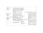
7. Intro to Object-Oriented Classes................... 8-1
7. Intro to Object-Oriented Classes
7.1 Structure/Records.............................................................. 8-3
Now that you have a basic understanding of standard
types, variables, and functions, and how to organize a
multi-module program, we will venture forth into
advanced types. Advanced types are programmer
defined, and usually aggregate (sometimes called
composite) types. By this I mean that YOU will be able
to specify the details of a new type, each instance of
which is possibly made up of several standard types.
For instance, a string of characters, or a university’s
student record (e.g. name, address, phone number).
Readings:
•
•
•
Chapter 4 [Savitch2001]
It is optional, if you understand the lectures, whether you
read Chapter 5. The same material is taught in my lectures
the way I like (e.g. static functions and static attributes,
overloading, constructors, design info hiding). Some of
these topics will definitely be on the midterm. I would
encourage you to read Chapter 5 (except 5.6-5.8), though I
would not say it is a requirement if you fully understand
this section of the lecture notes. But if you are struggling
with the material in this course, there is no substitute for
seeing more code and more source code explanations like
that in Chapter 5.0-5.5.
Chapter 5.6-5.8 are relevant for good students, or those
going on in Computing Science, or will be covered much
later in the course.
Copyright 2002 by R. Tront
7-1
7.1.1
7.2
7.3
7.4
7.5
Example of Struct ................................................................8-5
Modules as Abstract Types ............................................... 8-8
A Conceptual Problem .................................................... 8-14
Classes............................................................................... 8-16
Appendix - Object Orientation....................................... 8-26
7.5.1
7.5.2
Software Engineering Phases ............................................ 8-26
What Is Object-Orientation? .............................................8-27
7.6 Object Modeling............................................................... 8-28
7.6.1
7.6.2
7.6.3
7.6.4
Introduction to Modeling in General................................. 8-28
Entities vs. Objects ............................................................ 8-29
Object Data Analysis......................................................... 8-30
Object Attributes and Attribute Values ............................. 8-31
7.7 Object Relationship Diagrams........................................ 8-32
7.7.1
7.7.2
Object Icons....................................................................... 8-32
Relationships ..................................................................... 8-33
7.8 System Behavior............................................................... 8-34
7.8.1
7.8.2
7.8.3
Event-based Partitioning ...................................................8-34
External Design (User Manual)......................................... 8-35
Use Case Scenarios ...........................................................8-35
7.9 Object-Oriented Architectural Design........................... 8-37
7.9.1
7.9.2
Object Communication Diagrams (OCD) .........................8-37
Scenario Call Trace Design ............................................... 8-39
7.10 Synthesizing Object Requirements ................................ 8-41
7.10.1
7.10.2
7.10.3
7.10.4
Step 1 - Generate As Scenario-Starting Event List ...........8-41
Step 2 - Blank Master OCD .............................................. 8-41
Step 3 - Make an Internal Call Trace for Each Scenario... 8-43
Step 4 - Take the Union of All Traces ...............................8-49
7.11 Alternative Control Architectures.................................. 8-51
7.11.1 Centralized Scenario Design .............................................8-52
7.11.2 Roundabout Route Scenario Design ..................................8-55
7.11.3 Principle Object-based Scenario Design ........................... 8-56
Copyright 2002 by R. Tront
7-2
7.1 Structure/Records
The nice thing about structures is that:
The C and C++ programming languages have an
aggregate/composite ’structure’ type. Pascal has
something similar called RECORD. Java does NOT
have structures. However, I want to introduce
structures to you so that you can see why Java and C++
have the class construct, and why C++ doesn’t really
need structures, and Java even have have structures.
•
Structures are way of allowing programmers to define a
new kind of type, and give it a type name of the
programmer’s own choosing! Thus our programming
will not just be confined to the primitive types like int,
float, etc. For example, we could define a new
composite type called ‘Student’ which had record
fields within it for name, address, phone number, date
of birth. Once you have a new type name, you can
create many variables of that new type (just like
creating many variables of type int). e.g.
Student student1;
Student graduatingStudent;
•
they can hold several different types of fields (e.g. name
string, integer age) in one composite container (i.e. in one
composite variable; think of it like an ice cube tray.).
they can be assigned from one to another as a whole. This
is easy in Pascal/C++, and possible but not as direct in
Java. In C++:
graduatingStudent = student1
//C++
Note that we do not have to assign the various parts of
student1 (e.g. name, address, phone, age), each
individually, to graduatingStudent. We can treat
student records as a whole.
Structures are the first step on the road of encapsulation
and abstraction: putting things together that belong
together, and be able to treat the composite as a whole.
Often a client programmer can treat structures as a
whole without needing or wanting to know their
internal details. Client programmers are those who use
composites types defined and programmed by other
programmers. (Do you really need to know how
System.out works as long as it does its job?)
Each variable is called an ‘instance’ of the type.
Copyright 2002 by R. Tront
7-3
Copyright 2002 by R. Tront
7-4
7.1.1 Example of Struct
Here is how you declare a new, programmer-defined
structure type called AirPosition in C++. You use the
keyword struct, create your own name for the type, and
in braces {} specify the list of elements you want in
your new type.
struct AirPosition{
//C++
double latitude;
double longitude;
long altitude;
};
It is convention to name user defined types to begin
with an upper case letter!
Here is how you can use a structure in C++.
AirPosition pos1, pos2;
pos1.latitude = -23.;
pos1.longitude = 49.5;
pos1.altitude = 35000;
pos2 = pos1;
//C++ only.
int height = pos1.altitude;
Note why the individual record fields have their own
names: If a structure contains two data attributes of the
same type, we must have a field/attribute name for each
so that we can later specify which one we may want to
assign to or from (if we want to mess with the
individual parts of the structure). In Pascal these would
be called (record) ‘field names’. In C++ they are called
structure or class ‘data members’ or ‘member
attributes’, or just ‘attributes’ (as in the attributes of a
student).
For those unfamiliar with geographic position terms,
latitude is a measure of the angle north or south of the
equator. Let us assume the south pole has a latitude of
Copyright 2002 by R. Tront
-90 degrees. Longitude is a measure of East-West
position relative to Greenwich, England.
7-5
//Here is how you do output in C++.
cout << pos2.latitute
<< pos2.longitude
<< pos2.altitude;
That is all there is to structures. You define as many
instances of AirPosition as you need. You use the socalled ‘dot operator’ to ‘reach’ into a structure to
either set or access the individual record fields.
Assignment of a whole structure instance is possible in
C++ and most languages because the three fields are
stored adjacent to one and other in RAM, and the
compiler just arranges to have the whole section of
RAM occupied by the source record instance copied to
pos2’s record location.
Copyright 2002 by R. Tront
7-6
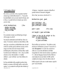
One thing that doesn’t work is outputting a structure
instance as a whole:
7.2 Modules as Abstract Types
cout << pos2;
// <--does not work!
This is because the compiler doesn’t know which of the
many possible ways you might like the output
presented:
•
•
•
•
-123 49.5 35000
-123, 49.5, 35000
(-123, 49.5, 35000)
-123 deg. longitude, 49.50000 deg. latitude, 35000 feet
Since we find it nice to put all the attributes of a record
together into one entity, it is interesting to ask the
question where do we put the functions that are
particularly related to the record?
It is very good program design to put all the stuff that is
related (e.g. attributes and functions) together. This is
for a number of reasons:
•
There are 3 ways to handle this:
1) As shown above, specify the attributes separately in a
compound output statement.
2) Write a print function that prints the individual attributes
one of a time, then call that function any time you need
the record printed.
3) In C++ only, overload ‘<< ‘ with a new meaning to
handle AirPositions (not possible in Java).
•
•
Copyright 2002 by R. Tront
7-7
Humans like the simplicity of working with abstract
concepts that are cohesive (belong together) and
encapsulated (located together). This applies to the
functions that go with new programmer defined composite
types. Programmers begin to think of the attributes and
functions together as a whole entity, just like we began to
think of Student and AirPosition as whole ‘things’.
Putting such program elements together is good, because if
we have to change something about the way we
programmed AirPositions, it would be nice if the attributes
and functions are all in one single source code module/file,
rather than scattered about several 100,000 lines of code in
100s of source code files.
It turns out that such program entities are very good
intermediate level building blocks with which to construct
programs. Though we may in future maintenance need to
add an attribute to a Student entity, or change or add a
function that deals with students, it is unlikely that we will
need to rip a student module apart, or join two together.
Copyright 2002 by R. Tront
7-8
This is because the ‘Student type’ is fundamental to our
University Registration system, and the Airplane type is
fundamental to an airline computer application.
So how do we provide functions that can be put
together with the structure? Java does not have
structures/records, at least not in the way that C++ and
PASCAL have them. However, in Java and almost any
other language you can define both variables and
functions in one source code file. Here is a crude way
to do it using static attributes and static functions;
class AirPosition{
static double latitude;
static double longitude;
static long altitude;
static void drop(int dropHt){
altitude = altitude - dropHt;
}
static void climb(int climbIncr){
altitude = altitude + climbIncr;
}
static void initialize(
double lat,
double myLong,
long alt){
latitude = lat;
longitude = myLong;
altitude = alt;
}
}
So here we have a useful source code module. We can
do lots of things with it. From another Java main
program class module, we could do this:
Copyright 2002 by R. Tront
7-9
Copyright 2002 by R. Tront
7-10
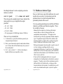
Notice from MyMainClass how we can set the
AirPosition static attributes, how we can call functions
within the AirPosition class that operate on the
AirPosition static attributes, and how we can get the
values of the AirPosition attributes for use in other
computations within MyMainClass, or output them
from MyMainClass. This is the essense of cohesion
and encapsulation, where AirPosition provides a nice
set of attributes and functions for some programming
problem.
public MyMainClass {
public static void main(String[] args){
AirPosition.latitude = 135.;
AirPosition.longitude = 23.;
AirPosition.altitude = 40000;
AirPosition.drop(1000);
AirPosition.climb(5000);
long height = AirPosition.altitude;
System.out.println(AirPosition.altitude);
AirPosition.initialize(50.38, 23.5, 29000);
System.out.println(
AirPosition.latitude + " " +
AirPosition.longitude + " " +
AirPosition.altitude);
}
}
Notice that from MyMainClass, you have to specify the
name of the Airposition class and a dot ‘.’ before each
use of a static variable or static function in another
class. The reason for this is that the class
MyMainClass may also have a static variable called
altitude, and you need to differentiate between the one
within MyMainClass and the one within AirPosition!
Copyright 2002 by R. Tront
7-11
An important aspect of static variables, is that because
they are outside of all functions, they can be used by all
the functions in the AirPosition class. One AirPosition
function can leave a value in an AirPosition static
variable that can later be picked up and used by another
AirPosition function, or even later by the same function
invoked again. In addition, if we have not labelled the
AirPosition static variables ’private’ (to be discussed
later), even functions in other classes like MyMainClass
can access AirPosition’s static variables. Note: It is
not considered wise to have all variables publicly
usable to other classes and we will discuss this later in
the course.
Also notice how you define and call a function with
multiple parameters. Just separate the parameters with
commas. The formal arguments that you pass in the
Copyright 2002 by R. Tront
7-12
function call can be literals, variables, or expressions.
There must be exactly the correct number of parameters
and each must be of the correct type (or at least be
assignment compatible with the formal parameters in
the function definition). At the start of the function
call, the first argument is copied to the first formal
parameter, the second argument is copied to the second
formal parameter, etc.
Also, you might notice how in the AirPosition
initialize( ) function definition that we can copy the
incoming parameters to the static attributes. Obviously,
your formal parameters have to have different names
than the static attributes or else the compiler will not
understand which you are referring two at any
particular point in the initialize( ) function.
7.3 A Conceptual Problem
Now we have a problem. What if we need two
AirPositions in our main program? And what if we
wanted to assign one air position to another.
If we were programming in C++ or Pascal, we would
just create an AirPosStruct structure type within the
AirPosition source code module, and allow the main
program to create multiple instances of it.
In addition, we could modify the AirPosition class
functions to have member functions parameter lists
like:
static void drop(int dropHt,
AirPosStruct & position){
position.altitude =
position.altitude - dropHt;
}
Now MyMainClass could create hundreds of
AirPosition structures, and have the AirPosition class
functions operate on it in any way necessary. e.g.
AirPosStruct pos1, pos2;
pos1.altitude = 5000;
AirPosition.drop(1000, pos1);
Copyright 2002 by R. Tront
7-13
Copyright 2002 by R. Tront
7-14
I have been a little sneaky here. The ’&’ character in
the formal parameter list has special meaning. It tells
C++ not to pass a copy of a structure, but just to pass a
reference to (i.e. the address of) the actual argument to
the function when it is called. This prevents the need
to wastefully make a copy of the structure at the start of
the call, modify it in the drop function, and make a
copy of the result to be returned to the calling program.
Passing by reference allow the compiler to set things up
so the called function can reach back into the caller’s
memory and manipulate the parameter remotely. Java
has a similar mechanism, however it is not optional like
the ’&’ is in C++. In fact, the only way to pass an
record object to a function in Java is ’by reference’.
C++ doesn’t need structures because it has a better
mechanism, called object classes. However, because
the older C language had structures, they were retained
in C++ because for the most part you can compile C
programs with a C++ compiler. So structures were
retained in C++ for backwards compatibility.
However, Java is a completely new language. Though
it looks a little bit like C++, the Java language designers
had a clean slate when they designed Java. So they
didn’t bother with structures since a class can do
anything that a structure can, and more.
Copyright 2002 by R. Tront
7-15
7.4 Classes
A class is a concept from so-called ’object-oriented’
programming languages. The word ’class’ has the
same meaning as a ’type’. It is a classification of
variables that are all the same. Like the classification
all ’int’ variables. Or the classification all ’Student’
variables. Or all ’AirPosition’ variables.
So these English terms are equivalent in computing
science:
class = = type
instance = = variable
A class has 4 major parts:
1) static attributes shared by every function in the class.
2) static functions shared by every function in the class.
3) instance attributes, which provide a template by which
we can make any structure-like instances.
4) instance functions, which provide the programmer with
the illusion that each structure instance has particular
functions that are available with it.
Instance functions makes the instances seem alive, because
they can respond to function calls.
So, this is like a flock of sheep. There is the
shepherd’s memory (like a memory of how many sheep
Copyright 2002 by R. Tront
7-16
are in the flock), and the shepherd’s ability to react to
requests. There is also zero, one, or many sheep in the
flock. Each has a memory (e.g. the instance attributes),
and each sheep can respond to stimuli (e.g. you shear
all the wool off the sheep and he will say "Baaaah").
public class AirPos{
//--------------------------//shepherd attribute(s).
static int population = 0;
//--------------------------//shepherd function(s).
static AirPos newAirPos(){
population = population + 1;
return new AirPos();
}
I admit this is not a great analogy, but I have not found
a better one that is better, more visual, and easy to
understand. In many textbooks, there are mistakes
made about object-oriented classes. They don’t make
clear that:
•
•
//-------------------------//sheep/instance attributes.
double latitude;
double longitude;
long altitude;
one of the nice thing about static methods is that they are
always there, even if the flock has no sheep in it currently
(i.e. even if you have not created any variables of type
sheep). This is why they are called static!
Most textbooks also WRONGLY state that the static
member functions cannot call instance member functions.
This is completely wrong. If a shepherd can find a sheep,
then he can get it to respond to some function invoking
stimuli (e.g. kick it and it will say "baaaah"). All that the
shepherd needs to know is the name of a sheep variable.
//-------------------------//sheep/instance functions.
void drop(int dropHt){
altitude = altitude - dropHt;
}
void climb(int climbIncr){
altitude = altitude + climbIncr;
}
Though this is a crazy analogy, it is particularly vivid in
alleviating some gross misconceptions about classes.
void initialize(double lat,
double myLong,long alt){
latitude = lat;
longitude = myLong;
altitude = alt;
}
So now let’s look at a class:
}
Copyright 2002 by R. Tront
7-17
Copyright 2002 by R. Tront
7-18
Notice the 4 standard parts in this class definition.
The static attribute ’population’ is an example of a
class’s shepherd-like memory. It is there all the time,
I’ve initialized it at the beginning of the program to
zero, and every time another program module calls the
function newAirPos( ), the population variable is
automatically incremented. Well, not automatically --the programmer wrote that static function to do that.
variable, and what types and names the attribute fields
will have.
Finally, see that there are three instance functions.
They are instance functions because they do not have
the keyword static on them. This means they are only
directly usable from an existing AirPos instance (i.e. a
particular sheep).
Ok, let’s see how a class is used in a program.
The second executable statement within the function
newAirPos( ) illustrates how you get Java to use the
template for new sheep memory to create a new sheep
instance. A reference to the newly created sheep is
returned to the calling program.
An AirPos variable (i.e. instance) is basically a
structure composed of three attributes:
double latitude;
double longitude;
long altitude;
Notice these to NOT have the static keyword on them.
This means they are instance attributes and these three
statements provide the template for manufacturing new
variables of class (i.e. type classification) ’AirPos’!
This is like a template for making extra sheep where
each sheep has latitude, longitude, and altitude
variables in its memory. It tells the compiler how
many bytes of RAM are needed for each new AirPos
Copyright 2002 by R. Tront
7-19
Copyright 2002 by R. Tront
7-20
Notice:
public class MyProgClass {
public static void main(String[] args){
•
AirPos pos1, pos2;
•
pos1 = AirPos.newAirPos( );
pos1.latitude = 135.;
pos1.longitude = 23.;
pos1.altitude = 40000;
•
pos1.drop(1000);
pos1.climb(5000);
long height = pos1.altitude;
System.out.println(pos1.altitude);
pos2 = AirPos.newAirPos( );
pos2.initialize(50.38, 23.5, 29000);
•
System.out.println(
pos2.latitude + " " +
pos2.longitude + " " +
pos2.altitude);
System.out.println(AirPos.population);
}
•
}
Obviously we need to discuss this.
Copyright 2002 by R. Tront
7-21
We can create one, two, or thousands of AirPos instances
(i.e. sheep).
However, they are not really created yet. Defining an
instance of type AirPos only reserves room in RAM for a
pointer (called a ’reference’ in Java) to an actual sheep.
Unlike other programming languages, in Java, every object
instance variable does NOT actually contain the instance
data itself.
To actually get an instance created, we need to use the
’new’ operator as shown inside the newAirPos() static
function I wrote. I will show you how to simplify this
later. This operator returns a reference to (i.e. the address
of some memory for) a new instance. This is in turn
returned to my main function and assigned to the waiting
reference variable called pos1 (which is exactly the kind of
variable needed to hold a pointer to an AirPos instance).
I can set any non-private attributes of the instance.
However, note that I use pos1.latitude rather than (as I did
previously) AirPos.latitude. I have to do this because
there are actually two AirPos references in my main
program file, pos1 and pos2. I have to specify which one
I am wanting to set the latitude of!
I can also get and use the value of any non-private attribute
of any instance by using the particular instance name, a
dot, and the attribute name.
Copyright 2002 by R. Tront
7-22
•
I can have an object manipulate itself and do ANYTHING
else its instance function is programmed to do, by invoking
an instance function. Instead of prefixing the function
name with a class name and dot, I now have to specify an
instance name. This is because the function invocation
needs to contain not only the name of the function and
its parameters, but also which particular instance needs
to be told to drop altitude.
This is sort of like the function signature we had back in
the Section 8.3 that looked like:
AirPosition.drop(1000, pos1);
Compare that with:
pos1.drop(1000);
All the information is available in the latter more compact
form, at least if you assume that pos1 knows the class of
object that it is pointing too (and Java assures that it does).
So although it looks like each instance has its own drop( )
function, we do not wastefully duplicate it dozens of times
for perhaps dozens of AirPos instances. Instead, Java, and
all object oriented languages, just make it look like it does.
Behind the scenes, Java just has one drop( ) function usable
by all the AirPos instances, and passes one extra but hidden
parameter containing the instance reference to the function.
This allows humans to write programs that allow us to feel
like we are telling reactive object instances to do some
particular function. This is the basis of ’objectorientation’: that a program is the sum of a bunch of
Copyright 2002 by R. Tront
7-23
•
reactive software entities that send messages (i.e. function
calls) back and forth to each other to get the job (i.e. user
command) done.
Finally, at the bottom of the main function, you can see that
I can get a printout of the current population of AirPos
objects by accessing the population static variable in the
normal way.
I don’t want to give the impression that the static parts
of a class are necessarily supervisory like a shepherd is
of a flock of sheep. Sometimes the static member
functions are not even present if all you need are
instances and instance functions. However, the static
part of a class often has supervisory kinds of roles. It
may keep track of population, it may keep track of
where each sheep is, it may keep track of what file the
sheep are perhaps being written too, etc.
So now you know why the main function of every
program is static. It is static, so that it is present when
the program starts up and there aren’t any sheep yet to
call upon. Also it is static because we only need one
main function, not one for each sheep we create.
So you can think of a class as 1+N reactive software
entities: the shepherd memory and functions, and the
memory and functions of N sheep you have created.
Each sheep has the exact same attribute field types and
functional behaviour. However, a sheep’s attribute
Copyright 2002 by R. Tront
7-24
values may be different than its neighbor’s. That’s
what makes each sheep different (other than the name
of its reference). And those attribute value differences
may cause it to behave slightly differently when one of
its functions is called, because the instance functions
uses that particular sheep’s attribute values when
executing (e.g. if (myAge > 2) then die!). This is why
we sort of think of object instances as having
intelligence: They have the ability to make decisions
about how they respond to function calls. They also
have self-awareness, because they know their own
attribute values and also can react differently to a
function call depending on its own particular attribute
values.
7.5 Appendix - Object Orientation
This rest of this lecture is an appendix containing
multiple subsections of an introduction to object
orientation, to object-oriented analysis (OOA), and one
very nice technique for object-oriented design (OOD).
Read this Section as far as you can. If you are a
beginner and become too confused, you should stop
reading. If you are an advanced student, you will find
this appendix an amazingly enlightening introduction to
software engineering object-oriented analysis and
design!
7.5.1 Software Engineering Phases
Most projects have several phases. Software projects normally
have:
• An analysis phase to gather and record the requirements,
• A design phase to plan the architecture and implementation
strategies to be used, and
• An implementation phase where code is written.
• A quality assurance aspect. Final quality of the product is
assured by actions taken throughout the project. e.g.
Read the above paragraph again as it is VERY
IMPORTANT!
- requirements, design, and code reviews,
- unit and system testing, and
- appropriate configuration management.
Approximately 15% of projects fail or are cancelled, usually
because of failure to do some these aspects of the project properly.
Copyright 2002 by R. Tront
7-25
Copyright 2002 by R. Tront
7-26
7.5.2 What Is Object-Orientation?
7.6 Object Modeling
Often there are specialists who work on each aspect of a large
project. Object orientation means something different to each of
them:
• To business system analysts it means determining and focusing
on the business entities (e.g. sales item, customer, invoice, etc.)
about which information must be processed or recorded. This
pre-dates object-oriented languages.
• To a software designer, it is the architectural view that a system
satisfies each external command by the set of actions resulting
from the trace of calls or messages sent among various reactive
software objects to implement that request.
• To a programmer, it usually means programming language
syntax that allows the programmer to easily:
- view data as having reactive abilities, and
- re-use code via inheritance hierarchies, and
- have both type flexibility and ease of maintenance via
polymorphism.
7.6.1 Introduction to Modeling in General
A model is a representation of a actual thing. To a child, a model
is something created which is a ‘smaller’ but adequate likeness of
the real thing. To a car dealer, a model is a bunch of cars which
are near identical (cf. object ‘class’). In systems analysis, a model
captures the essential nature of something by indicating the
essential details that need to be stored about things of that ‘class’,
or by illustrating the flow of stuff required through a system, or by
specifying the sequential ordering (e.g. making paper in a pulp
mill, getting a university degree) within a process, etc.
Definition: A model is an alternate representation with an
‘adequate likeness’ of the real thing.
Some of the alternate representations we in systems design may
use for the actual things are:
• a diagram or picture
• a form or computer record
• a process description, data flow diagram, or finite state machine
The purpose of creating a model is to represent only the essential
characteristics of the thing so that:
• we may understand and clearly document the nature of the thing,
• we may store the essence of the thing for later retrieval,
• we may communicate the nature of the thing to someone else,
• they can think and/or reason about the correctness of the model
without:
- being distracted by the complexities of the complete real thing (i.e.
abstraction)
- having to travel to where the real thing is located
- having to see the function of a real thing while it is operating very
fast
Copyright 2002 by R. Tront
7-27
Copyright 2002 by R. Tront
7-28
•
•
we needn’t waste space storing useless information about the
thing,
we may write a program to implement a system which allows
humans to better administrate the processes in which the thing
participates.
7.6.2 Entities vs. Objects
The data that a system needs to store is mainly computer records of
the instances of various record types in the application domain
(e.g. orders, customers). Traditionally in information systems
analysis, these things were called entities. Each entity class has a
record/structure type with a different layout of attribute fields.
Order instances have order ID number, part ID designator, and
quantity of order fields. Customer records have name, address,
and phone number record fields.
More recently, is has instead become popular to call domain
entities objects. The term ‘objects’ has an additional implied
meaning that the model of the object we are documenting contains
data plus reactive abilities (i.e. plus ‘functions’, or ‘operations’,
‘behavior’, ‘ability to control things’, ‘intelligence’,
‘liveliness’(e.g. can be sent messages or ‘activated’)).
In fact, this idea is carried even further by OO languages. Rather
than procedures having data parameters, instead object data is
regarded as having operations/procedures that can be
triggered by a message. In fact, individual instance records (not
just ADT modules) are regarded as having procedures.
e.g. Instead of (in C):
struct CustomerType custRecord;
printRec(custRecord, theFastPrinter);
You do this (in C++):
CustomerType custInstance;
custInstance.print(theFastPrinter);
Notice this is not like C, nor like Modula-2 where you would have
done ModuleName.print(). The symbolic name to the left of the
Copyright 2002 by R. Tront
7-29
dot is a variable name (i.e. instance), not a module or class/type
name. The procedure now appears to be a field of the instance, as
if the instance ‘has/owns’ its procedures!
7.6.3 Object Data Analysis
In object data analysis, we try to determine an organized way of
diagramming and storing information about the various relevant
object types involved in the application domain. To a new analyst,
sometimes it is not immediately apparent what kinds of data might
need to be modeled. Examples of the object classes needed to be
modeled within an application might be:
• a physical object (e.g. person, aircraft, robot, printer).
• an incident or transaction that needs to be recorded either for
immediate use, for transmission to someone else, or for a
historical log (e.g. order, purchase, sale, boarding an airplane,
graduation, marriage, phone call). Note a purchase is from the
purchaser’s application’s point of view, while a sale is from the
seller’s. Interactions between two other objects sometimes fall in
this category.
• a role (e.g. student, client, customer, manager, spouse).
• an intangible concept (e.g. bank account, time delay, date, sound
recording),
• a place (e.g. parking space, warehouse #3, the 13th floor heat
control),
• a relationship (e.g. customer’s sales representative, a flight’s
captain),
• a structure - e.g. the list of an airplane’s component part numbers
(body, wings, engines, tail), possibly even a hierarchy.
• an organization or organizational unit (e.g. university,
department, corporation, submarine crew, sports team).
• a displayable field (e.g. string, icon, image) or printed report, or
an I/O signal
Copyright 2002 by R. Tront
7-30
•
Specifications or procedures- e.g. organic compound or recipe.
7.7 Object Relationship Diagrams
7.6.4 Object Attributes and Attribute Values
7.7.1 Object Icons
We use the terms ‘object class’ to mean group of instances of
things which have the same set of attribute names (e.g. car’s each
have a licence number, color, and weight), but which have
different values for each of those characteristics (this is what
makes the instances of the same class different from each other).
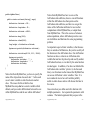
Let’s examine an example of an Object Relationship Diagram
(ORD) carefully. The one below shows two objects.
STUDENT
It is common for a class of entity instances to be modeled as a table
of fixed length records:
* student-id
STUDENT TABLE
- student-name
- student-address
student-id student-name student-address student-phone high-school
93010-1234
Smith, Bill
123 Second St.
420-1234
Mt. Douglas
92010-4321
Jones, Jane
234 Third St.
123-4567
Burnaby
91111-1056
Able, Jim
345 Fourth Rd.
822-9876
John Oliver
Graduated
From
Graduated
* high-school
- school-address
- school-phone
- student-phone
- high-school
This concept is in keeping with the view that a student file is a list
of fixed length records.
Each column represents an attribute of the type ‘student’ (i.e. a
field of a student record). The legal set of values that an attribute
may take on is called the domain of the attribute. Examples are
date = (1..31), and day= (Sunday..Saturday).
Each row represents a particular instance of a student. Often the
rows are sorted in order by a particular column or columns. That
column(s) is called the primary key.
Copyright 2002 by R. Tront
HIGH-SCHOOL
7-31
In is not clear whether they are object instances (since there titles
are singular) or entity classes (since only their attribute names and
not attribute values are shown). Normally in ORDs it is not really
important that you differentiate between whether the boxes are
classes or instances. You will probably find it best to think of
them as generic instances (not having had attribute values
assigned yet). i.e. they are an object storage/record layout plan.
Note that instead of having the attributes listed horizontally, as in
the column titles of a table, we have the attributes listed vertically.
This is widely done, though there is no reason for this except it
makes the entity icons have a smaller maximum dimension. Also,
note that the attribute(s) on which the records are sorted are called
the primary key of the entity, and are labelled with a ‘*’.
Copyright 2002 by R. Tront
7-32
7.7.2 Relationships
7.8 System Behavior
Object-Relationship Diagrams (ORDs) contain both entity classes
and the relationships between them. An example of a relationship
is that between a student and a high school.
Recent methodologies suggests that you start analysis by
determining an application’s data model first. Even for nondatabase projects, this identifies early the application domain
objects which will most likely form core software elements of
the eventual implementation. In particular, the names of the
important objects, their attributes, and their relationships are
researched. Once this is done, we are in a better position to plan
the implementation of the behavior of the system.
STUDENT
HIGH-SCHOOL
* student-id
- student-name
- student-address
R1
Graduated
Graduated
From
* high-school
- school-address
- school-phone
- student-phone
- high-school(R1)
Fundamentally, relationships are illustrations of links between
entities. These links are simply (but importantly) the referential
routes that could be traversed by the application code to find other
related data. Note that the high school attribute in the student class
is a foreign key which provides the information needed to traverse
R1. A foreign key is a value- or pointer-based reference to
particular related instance (e.g. particular high school). Valuebased foreign keys refer to the primary key of the other related (i.e.
foreign) object.
ORDs provide a map showing all possible ‘routes’ over which the
application can navigate around the data. For instance, given a
student object, how does the application code find out the phone
number of the high school she went to? Answer: Look in the High
School attribute of that student to find out which high school, then
find that high school record in the high school database, then look
at the school-phone attribute in that record.
Previously, programs were regarded as a main module and
subprograms which implementing an application’s functionality.
The newer, more object-oriented view is that a system’s behavior
is simply made up of the sum of the behaviors of the object
classes and instances in the system . The objects collaborate
together during execution to get each user command done.
You can see why we had to identify the core object classes first, as
it is they what we now propose to embody with a behavioral
nature. But before we start writing code for the system’s objects,
we have to decide what behavior each will contribute to the whole.
The next question then, is what behavior does each object class and
instance need to export to the system, in order to that it satisfy it’s
behavioral responsibilities to the application? In the next few subsections of the lectures, I plan to introduce a very beautiful
mechanism to synthesize the required behavior for each object
class and instance.
7.8.1 Event-based Partitioning
Modern applications are event-driven in nature. Think of your
personal computer; it idles for billions of instructions waiting for
an event like a mouse click or a clock tick.
With this view, we will design the system by looking at how each
external command or scenario-starting event is handled by the
system. By looking at each external command/event one at a time,
Copyright 2002 by R. Tront
7-33
Copyright 2002 by R. Tront
7-34
we can reduce the scope of what we have to think about at any
point in the design process to handleable proportions. When
writing a requirements specification for a system, it is not
uncommon to first list or diagram all the sources of external
commands/events that the application must interact with (e.g.
keyboard, mouse, clock, network, printer, etc.). Then in more
detail, you should name/list each kind of event/command that the
application program is to handle from each source.
We could thus define:
• ‘scenario appearance design’ to be deciding how a use case
would appear to a user (i.e. write the user manual), and
• ‘scenario call trace design’ (or ‘scenario implementation design’)
to be deciding the internal software architecture for a use case.
7.8.2 External Design (User Manual)
Before beginning architectural design, it is not uncommon to write
a draft user manual to firm up the behavior expected of the system
for each user command. This sounds weird to some people who
feel the manual is written after the coding is done. But those who
finish Cmpt 275 realize that:
• you can’t write the code until everyone on the team knows what
the program is supposed to ‘look like and behave like’!
• Often this look and behavior must be approved by someone else,
so rather than spending months first writing a program that is not
what the customer wants, you instead spend a week writing a
draft version of the user manual for customer pre-approval.
7.8.3 Use Case Scenarios
An individual command may have several steps that should be
documented in the draft manual. An example sequence might be
clicking a menu command, entering several pieces of data in a
dialog box, then clicking OK, the application checking and saving
the entered data (often different pieces in different objects), then
finally telling the user that the command is done and waiting for
the user to click OK again. This is called a use case scenario.
Later during architectural design, we must plan what part of
each step of a use case scenario will be handled by which
different object.
Copyright 2002 by R. Tront
7-35
Copyright 2002 by R. Tront
7-36
7.9 Object-Oriented Architectural Design
Though there are many aspects to architectural design, we will
concentrate here on the design of internal call traces for the
scenarios. [Rumbaugh96] states “designing the message flows is
the main activity of the design phase of development”.
Main
start_accepting
Event Generator
(e.g. User Interface)
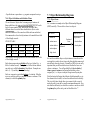
7.9.1 Object Communication Diagrams (OCD)
It has been common for many years to sketch a diagram indicating
which procedures, or more recently which modules, call/
communicate/interact with which others. This provides an
interaction context which provides further understanding and
documentation of the purpose, responsibilities, and dependencies
of a module (often one module depends on services provided by
another via exported procedures).
Very recently, we have started to diagram object (rather than
module) interactions, and thus named such diagrams Object
Communication Diagrams (OCDs) or Object Interaction Diagrams.
Typically, each object class in your ORD which is reactive should
be put in your OCD (note: some structures which are simply data
records are not reactive and needn’t show in the OCD). Also, you
may consider modules which are not objects (e.g. the main
program or other utility modules) to be reactive objects. The
primary consideration here is that we identify islands of reactive
ability/behavior/intelligence/data/control. These islands (i.e.
components), working together, implement the behavior of system.
UC1()
init_A()
Senior Object A
full?()
init_B()
7-37
enqueue()
add()
init_C()
Object B
Object C
enqueue()
Note that such a diagram is not to show ‘relationships’, but instead
interactions. Two objects which have no data relationship could
potentially send messages (i.e. call) each other. So an OCD is a
somewhat orthogonal view of the objects in a system, and provides
a kind of 2nd dimension to their definition.
Copyright 2002 by R. Tront
UC2()
Copyright 2002 by R. Tront
7-38
Though this looks like a call structure chart, in fact the rectangles
are to be regarded as components (i.e. modules or object classes)
which export several differently named functions!
The main concept here is to regard and diagram the system as a
collection of interacting reactive objects. The arrows show
messages (e.g. procedure calls) from one object to another.
Receiving objects should be programmed to react appropriately to
each message which they receive.
7.9.2 Scenario Call Trace Design
In order to determine each reactive component’s responsibilities
and the operations it must export, we will examine how each
module participates in each use case scenario. In order to reduce
the complexity of this design step, we do this one scenario at a
time.
In the movie industry, planning for a film segment to be shot is
often done on a ‘story board’. The sketches on this board provide
anticipated camera shots (angles, scenery, costumes) at various
moments through the progression of the scene. In essence, the user
manual provides sketches of what the application will look like and
do, at various points through each scenario. It is a story board.
Scenario call trace design will also be done using a kind of story
board. A visual plan and textural explanation of which procedure
calls will be made (and why) between which objects at each point
during the execution of the scenario.
External events will be the primary driver in our design process.
More specifically, a scenario-starting external event is a special
kind of external event which initiates a sequence of interactions
between the user and the application which carries out a use case
scenario as described by the use manual. In menu-driven
applications, menu selection events start most use case scenarios.
The activation of a menu command results in the application
receiving a message from MS-Windows. The user interface
component of the application which handles these messages
subsequently makes procedure calls to other application objects
appropriate for the command, and these objects may in turn call
other objects or modules.
If the menu command starts a long dialog with the user to enter a
number of pieces of data (e.g. customer name, address, phone
number) one after the other, the calls may solicit other external
events associated with that scenario. These latter events are
termed ‘solicited’ as the application subsequently solicits specific
further input from the user as is needed to complete the command.
The application responds to each solicited event in the appropriate
way for that step of the scenario (e.g. read the data, do something
with it, prompt for the next entry).
Note: We could also call this scenario message trace design,
because in the Smalltalk OO language, function calls are termed
‘sending a message’ to another object. Yet other names could be
scenario implementation design, scenario event trace design, or
scenario internal interaction design.
Copyright 2002 by R. Tront
7-39
Copyright 2002 by R. Tront
7-40
7.10 Synthesizing Object Requirements
This subsection looks at a beautiful, step-by-step process by which
the requirements for individual reactive components can be
obtained from the overall system requirements (as embodied in the
use cases).
Main
Event Generator
(e.g. User Interface)
7.10.1 Step 1 - Generate As Scenario-Starting Event List
From the user manual, generate a list of all scenario-starting
external events that are required to be handled by the application.
There could be dozens or hundreds in a big system.
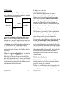
7.10.2 Step 2 - Blank Master OCD
An Object Communication Diagram is a diagram which shows the
objects from the ORD in a diagram without the relationships, and
shows additional reactive components such as main, UI, and
control modules. Generally, the objects are not placed in the same
position on the diagram page as they were in the ORD (where they
were arranged to make the relationships most tidy). Instead, place
the objects in a hierarchical manner radiating away from the
principle external event source (typically the user interface).
Senior Object A
Object B
Copyright 2002 by R. Tront
7-41
Copyright 2002 by R. Tront
Object C
7-42
7.10.3 Step 3 - Make an Internal Call Trace for Each Scenario
Make many copies of the blank OCD diagram, one for each
scenario-starting external event. For each scenario-starting event,
design a trace for the anticipated calls needed to implement the
proper response to that external event. (Some of the design issues
which impact the choice between different trace options are
discussed later). Document the trace on a single, blank OCD page.
(By confining ourselves to designing one scenario’s
implementation at a time, we need not be distracted by arrows
involved in other scenarios).
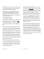
• The first scenario you should consider is the ‘program start’
event. This scenario should be designed to have the main
module send a tree of internal initialization events (i.e. calls) to
the key objects telling them to initialize (open their files, set
stack to empty, etc.). The principle of low coupling dictates that
the main module should not know the name of all the objects/
modules in the system, but only those directly below it. Those
mid-level objects in turn send initialization messages to their
subordinate objects. Any of these calls might create a number of
default RAM objects as necessary for the initial functioning of
the program. Once the system is initialized, the main tells the
external event source components (e.g. the user interface) that
they can start accepting external user events.
Start-up Implementation Call Trace
Main
1: init_A()
Senior Object A
2: init_B()
Object B
Copyright 2002 by R. Tront
7-43
Event Generator
4:start_accepting() (e.g. User Interface)
Copyright 2002 by R. Tront
3: init_C()
Object C
7-44
•
Label each message/call with a number indicating it’s sequence
in the execution of that scenario, and with the name of the
procedure being called.
On another diagram, for the first external scenario-starting event
on your list, draw the trace of calls/messages that will be sent
from the external interface object receiving the starting event to
the principle reactive objects required to implement the response
to that event. This will, in turn, sometimes cause an intermediate
control/handler object to send one or more internal messages on
to one or more other objects. Give each internal message a
sequence number and a name which indicates what procedure is
being called (or what the purpose of the message is).
Each time you do this, you must think of all the internal object
interactions that could take place in handling a particular
external event. For instance, to register a student in a course
offering, you must first check whether the course offering exists
before adding a record to the association object called studentregistration.
For each diagram, it is usually necessary to document in either a
paragraph, list of steps, or pseudo-code, a textural description of
how the scenario is planned to be implemented. e.g. “check
course exists and has space, then add student to course offering,
and update available remaining course space”. This provides
reviewers and subsequent implementation programmers with a
more understandable idea of how the scenario is to unfold.
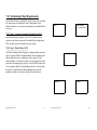
User Command #1 Implementation Call Trace
Main
2:UC1()
1:full?()
Senior Object A
3:add()
Object B
7-45
Object C
4:enqueue()
•
Copyright 2002 by R. Tront
Event Generator
(e.g. User Interface)
On a yet another diagram (see next page), do the same for the
second user scenario-starting event on your list.
Copyright 2002 by R. Tront
7-46
•
User Command #2 Implementation Call Trace
Main
Event Generator
(e.g. User Interface)
On a last diagram, show which module(s) can initiate program
shutdown, and the trace/tree of calls to the reactive components
which need to be informed of the upcoming shutdown. Such
components, upon being notified, shut files, flush buffers, reset
the video display mode (e.g. from MS-Windows graphic mode
back to DOS text mode, etc.), and delete themselves as
appropriate, before the main program ends. (I have not drawn
this trace to keep the resulting OCM simple).
2:UC2()
1:full?()
Senior Object A
3:enqueue()
Object B
Copyright 2002 by R. Tront
Object C
7-47
Copyright 2002 by R. Tront
7-48
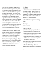
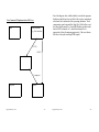
7.10.4 Step 4 - Take the Union of All Traces
Notice in particular how two different scenarios both had calls to
the full() procedure of class Object_C. The (first) union operation
has merged these two into one arrow in the overall OCD. All
sequence numbers should be removed from the labelled arrows
since with so many different scenarios shown, they no longer make
sense.
The result is the complete Object Communication Diagram:
Main
start_accepting
Event Generator
(e.g. User Interface)
The result is a fantastic diagram!
• The (first) union synthesizes an OCD from which the
requirements spec for an object class can be determined.
Obviously, the class must export a function for each different
type of arrow entering it. e.g.
UC1()
init_A()
-
UC2()
Senior Object A
full?()
init_B()
•
enqueue()
add()
init_C()
•
Object B
Object C
enqueue()
Copyright 2002 by R. Tront
7-49
The UI must export start_accepting().
Object A must export init(), UC1(), and UC2().
Object B must export init_B() and add().
Object C must provide/export empty(), enqueue(), init_C(), and
enqueue().
Notice that the above list seems to imply Object_C should export
enqueue() twice. By taking a second union, you can merge the
two different enqueue() calls to Object_C (which are not merged
by the first union because they are from different callers), into
one item in the list of procedures that Object_C must export.
Basically you must regard the list of exported procedures as a
true ‘set’ where duplicates are not allowed.
In addition, you get a requirements spec for each object’s
responsibilities to call/notify other modules/objects. An object
will do some internal processing when called, and then likely
some interaction with other objects. The diagram shows all the
other objects that a particular object is planned to get info or
processing from, or must notify in order to fulfill its
responsibilities. e.g. Senior Object_A has the responsibility to
notify those below it that they should initialize themselves.
Copyright 2002 by R. Tront
7-50
7.11 Alternative Control Architectures
The above strategy is very powerful as it constructively
synthesizes the requirements for individual modules and object
classes from an application’s external requirements. This makes it
an extremely appropriate technique to bridge the so called ‘design
gap’ that exists between the end of analysis and the beginning of
writing code for individual modules.
Please note that there are many alternatives in constructing the
trace of a scenario. This is where the real design decisions are
made. (The diagramming with a CASE tool and the double union
are basically just documenting the design decisions and
constructively gathering object specifications from the traces).
Trace alternatives will be discussed in the next section of the
course.
As with all design, there are usually several alternate ways to
design a sequence of internal call events that will carry out a
particular scenario. For example, when the UI receives an ‘exit
program’ command from the user, should it send messages to all
the objects telling them to shut down? Or should it call a
procedure in the main module which should then tell the objects to
shut down? ‘Design’ is choosing between workable
implementation alternatives to pick the one that is most
elegant, most easy to maintain, uses the least memory, and/or is
best performing.
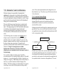
Let us consider a simple reservation system. Generally a
reservation instance is for a particular flight, sailing, or video rental
instance, etc. A reservation typically is related to a particular, say,
sailing via a foreign key. When dealing with user-entered data, we
must use every effort to maintain referential integrity of the
database. Thus before creating a reservation instance for a person
on a sailing, we must check that that particular sailing actually
Copyright 2002 by R. Tront
7-51
exists. This scenario implementation can be designed in one of
three alternative ways. These three ways will be shown in the next
3 sub-sub-sections.
7.11.1 Centralized Scenario Design
In this design, a particular reactive component which both is
informed when the scenario is to be initiated, and which
understands the scenario to be carried out, orchestrates the
execution of the scenario.
Although often not the ideal design, this component may the event
generator itself (e.g. user or network interface module), in which
case application scenario code (possibly unfortunately) gets added
to the event generator module.
.
Event Generator (UI)
1: checkExists()
Sailing
2: makeReserv()
Reservation
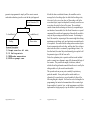
Alternatively, as shown below, an extra control module or object
can instead be added whose only job is to orchestrate scenarios. It
is not unusual for this module to export more than one function,
one in fact for each scenario to be orchestrated in an application (or
for a particular subset of scenarios in the application). The event
Copyright 2002 by R. Tront
7-52
generator is programmed to simply call the correct scenario
orchestration function given the event that has just happened.
In both the above centralized schemes, the controller sends a
message first to the sailing object to check that the sailing exists,
then waits for the return from that call, then makes a call to the
reservation object (supervisor/shepherd) to actually create the new
reservation, the waits for that call to return. The centralized
control scheme has the advantage of cohesively encapsulating in
one function of one module (be it the Event Generator or a special
component) the control and sequencing of internal calls needed to
carry out the processing needed in the scenario. Its advantage is
that if the control or sequencing of the scenario might later during
maintenance need change, only one function in one module needs
to be updated. Also notice that the sailing and reservation objects
do not communicate with each other, and thus don’t have to know
about each other (this is occasionally a good design feature). On
the other hand, the central object unfortunately gets coupled to all
the parameter types of all the lower calls.
Event Generator (UI)
1:UC5()
Central
2: checkExists()
Sailing
3: makeReserv()
Reservation
Scenario Description:
1) Prompt user for all info;
2) If Sailing exists
3) THEN make reservation
4) ELSE re-prompt user.
Notice the explanatory text or pseudo-code that can be included
under a scenario trace diagram to more fully document the logic of
the scenario. This pseudo-code might, for instance, indicate
whether the sailing information needed from the user is read by the
sailing module or by the central control module.
This pseudo-code may or may not eventually be put into any
particular module. It may end up in the central module, or
alternatively be spread out over several modules if either of the
following designs is adopted. It is therefore not to be thought of as
programming, but instead as documentation of the scenario logic
from an architect’s point of view, so that programmers could later
implement the design properly as per the architect’s specifications.
Copyright 2002 by R. Tront
7-53
Copyright 2002 by R. Tront
7-54
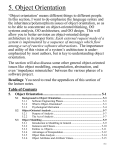
7.11.2 Roundabout Route Scenario Design
7.11.3 Principle Object-based Scenario Design
The name of this section is a Tront’ism and is not widely used
terminology. The idea is that control is passed from the initiator
(i.e. event generator) to the first module which must supply
preliminary checking or data, and then that module forwards the
request to the final object. The control thus travels a rather
roundabout path to the terminal object. When the makeReserv()
procedure is done, it returns control to the Sailing, which in turn
returns from the makeResIfSailingExits() to the initiator.
This design alternative has the initiator first informing the principle
application object involved, in our case the reservation object.
After that, the principle object (which may understand its creation
needs best) does whatever is necessary to accomplish the request.
In the example below, the reservation checks the sailing exists,
waits for the reply, then if ok makes a new instance of its type, and
then finally returns control to the initiator object.
Initiator
Initiator
1: makeReserv()
1:makeResIfSailingExists()
2: checkExists()
Sailing
2: makeReserv()
Sailing
Reservation
Reservation
Scenario Description:
1) Ask reservation to make an instance
2) It checks if Sailing exist.
If so reservation makes an instance,
3) ELSE return exception to initiator.
Scenario Description:
1) Ask Sailing if it exists, and if so
2) THEN have it make reservation
3) ELSE have it return an exception to
the initiator which will then
re-prompt the user.
This design strategy is particularly good if using asynchronous
one-way messages, rather than procedures calls, as it requires no
data to be returned to callers.
Note that these diagrams do not show the procedure returns, but
this design requires an OK to be returned to the reservation via a
parameter/return value. Either that, or if using one way messages,
a return message would have to be added to the trace.
Copyright 2002 by R. Tront
Copyright 2002 by R. Tront
7-55
7-56