1
3
DROP TOWER
This section provides a guide to the ZARM (Zentrum für Angewandte Raumfahrt Microgravitation) Drop Tower,
located in Bremen, Germany, which was officially declared an ESA External Facility on 2 October 2003. The
section begins with a brief introduction to drop towers and drop tubes.
3.1
Introduction
3.1.1
What Are Drop Tubes and Drop Towers?
Drop tubes and drop towers are ground-based research facilities with which up to ten seconds of free-fall
(weightless) conditions can be achieved.
Drop tubes are dedicated to containerless processing for fundamental studies of material properties and
solidification microstructures. Samples (usually liquid metal drops) are released from the top of the drop tube and
allowed to fall freely. The aerodynamic drag, which creates friction and subsequently convection in samples, can
be eliminated by operating the tube under vacuum, thus creating weightless conditions.
Drop towers are multi-purpose facilities, which enable autonomous experiment packages to be submitted to true
free-fall conditions. In most cases, drop tower experiments are performed in an evacuated chamber to eliminate
the effects of drag force. Their high degree of flexibility permits investigations in different research areas. A series
of experiments can be conducted over a period of a few days, enabling scientists to screen ranges and parameters.
Drop towers are very useful for obtaining quantitative data on physical phenomena with short characteristic times
in the absence of gravity-driven disturbances.
3.1.2
What Do Drop Tubes and Drop Towers Offer?
Drop tubes and drop towers provide:
3.1.3
Facilities for experiments that require less than 10 seconds of weightless conditions;
Precursor opportunities for carrying out research in preparation for long-duration missions;
Low-cost access to research in weightless conditions;
A short experiment planning-development-execution cycle;
A fast turn-around time;
The possibility of executing a series of experiments within a few days;
Direct intervention by research teams to make modifications between drops;
Minimal safety requirements;
A high quality low gravity environment (< 10-5 g);
A platform for new ideas in the field of microgravity research.
Why Use Drop Tubes and Drop Towers?
The main reason for using drop tubes and drop towers is that they are extremely useful to students and scientists
new to the field of microgravity research, as well as to experienced researchers wishing to execute numerous,
short, low-cost tests before (when foreseen) moving on to costly, long-duration missions. Even though the time of
weightlessness to perform experiments is of the order of seconds, the level of microgravity obtained is of
extremely high quality, providing good scientific data.
DROP TOWER
page 3-1
3.1.4
Principal Characteristics of the ZARM Drop Tower
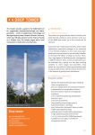
The ZARM drop tower is a 146 m tall concrete shaft (Figure 3-1), which provides near weightlessness up to 3
times a day, for experiments dropped from the top of the tower (4.74 seconds of microgravity) or catapulted
upwards from below the tower (9.48 seconds), respectively. In September 2004, a catapult system was
inaugurated at the ZARM drop tower (Figure 3-2), which doubles the standard drop microgravity time, and is
located in a chamber 11 m below ground under the tower. This catapult throws the capsule upwards from the
bottom of the tower, accelerating it by a pneumatic piston driven by the pressure difference between the vacuum
inside the drop tube and the pressure inside the tanks. The acceleration level is adjusted by means of a servo
hydraulic braking system controlling the piston velocity. This catapult system accelerates capsule masses from
300 kg up to 500 kg to a speed of 48 m/s within 0.28 seconds.
The microgravity lab system itself is a cylindrical capsule with a diameter of 800 mm and a length of 1.6 m or 2.4
m depending on the space required. Inserted platforms, held in aluminium frames, form the modular drop capsule
structure. After integration of an experiment prior to a drop or a launch, the whole capsule is closed pressure-tight
with an aluminium cover. When performing a drop, a winch pulls up the capsule to the maximum internal height
of 120 m. The specially designed release mechanism serves for low induction of disturbances during free fall. The
internal drop tube is evacuated before every drop or launch and the capsule is released/catapulted at a residual
pressure of 10 Pa. The internal tube, which has a volume of 1700 m3, stands detached at a height of 13 m on the 2
m thick roof of the deceleration chamber. The detachment of the tube from the tower itself is necessary to assure
quiescent conditions even during stormy weather. During the free fall period of a drop or launch, an ultimate
microgravity quality with residual accelerations less than 10-5g can be detected. At the end of the experiment, an 8
m high deceleration unit, filled with polystyrene pellets, decelerates the vehicle.
Figure 3-1: ZARM Drop Tower External View
DROP TOWER
page 3-2
Figure 3-2: ZARM drop tower interior layout
DROP TOWER
page 3-3
3.2
3.2.1
Physical Environment
Pressure Environment
The drop capsule is a gas-tight pressure vessel, sealing the interior from the outer drop tube vacuum. The interior
is kept at atmospheric conditions throughout the whole procedure, and the inner pressure is continuously
monitored as part of the housekeeping data. Pressure deviations may result from a temperature shift due to
differences of ambient temperature between the integration area and the top of the tube. In case of pressure
increases due to outgassing of experiments or high power consumption values, the pressure is released to the
surroundings only during the evacuation process. If the internal capsule pressure drops to less than 980 hPa, the
experiment procedure is stopped. The drop is initiated when the tube pressure is below 10 Pa. The actual values
are monitored together with the other tower data in the control room.
Table 3-1: Drop tower environment pressure parameters
PARAMETER
3.2.2
VALUE
Nominal capsule pressure (p)
1.013 hPa
Pressure loss (dp)
< 1 % in 3 hours
Safety range (p)
980 hPa – 1.300 hPa
Thermal Environment
The temperature of the interior of the capsule is continuously monitored and is in general maintained at room
temperature (RT). In winter, during the evacuation process, the temperature can drop to 0 °C. Therefore, for
sensitive experiments the inside of the capsule can be heated up to RT. Experiments can be connected to a thermal
liquid circuit, which is connected to a thermostat outside of the tube. Through closed loop regulation, the
temperature can be adjusted to between –20 °C and +60 °C. The circuit is disconnected about 90 seconds prior to
the drop command. An onboard heat exchanger with about 1 kW power can be made available.
Table 3-2: Technical data of the thermostat
PARAMETER
DROP TOWER
VALUE/CHARACTERISTIC
Temperature range
-20 °C to +60 °C
Liquid
Glycol/Water-Mixture
Heating power
Max. 2 kW
Cooling power at +20 °C
2.3 kW
Cooling power at –20 °C
1.2 kW
Volume of bath
19-27 litres
Maximum pressure
0.6 bar
page 3-4
3.2.3
Accelerations
3.2.3.1
Transition From 1g to 0g
Users who wish to initiate their experiments before the drop begins should keep in mind that the transition from
1g to 0g might create disturbing effects for the experiment. The release mechanism has been designed and revised
over the years to achieve a relatively smooth transition, but for some experiments it might still create relevant
disturbances (e.g. for levitation systems, experiments with long relaxation times, hardware like interferometers,
etc.). Figure 3-3 shows typical accelerations immediately after release of the capsule.
Figure 3-3: Typical accelerations immediately after release of capsule (Image: ZARM)
3.2.3.2
Residual Accelerations
The residual accelerations during the flight are generally as low as 10-6g to 10-5g. Figure 3-4 depicts the residual
accelerations during the drop of the experiment. The data in Figure 3-4 and Figure 3-5 were recorded during a test
drop of a capsule not containing an experiment. The capsule was equipped with batteries, a running Capsule
Control System (CCS), data transmission system, sensor platform and platforms loaded with screwed steel plates
to provide an experimental equivalent mass. The data presented is meant to provide the user with a reference data
set.
DROP TOWER
page 3-5
Figure 3-4: Residual accelerations during the drop (Image: ZARM)
Figure 3-5: Fourier spectrum of accelerations (after end of release transition) (Image: ZARM)
DROP TOWER
page 3-6
3.2.3.3
Deceleration Forces
The experimental hardware must be designed and mounted to withstand the deceleration forces encountered at the
end of a drop. Figure 3-6 is a typical deceleration curve of the ZARM drop tower. As can be seen, the deceleration
lasts for about 0.2 seconds. The average deceleration value is approximately 25 g, and the peak value reaches
about 50 g. For design purposes, these values must be considered as quasi-steady accelerations. The introduction
of a safety factor of 2 is strongly recommended. Therefore, the experiment must be designed to withstand a
deceleration of up to 100 g.
N.B. No damping elements are recommended: shock absorbers might lead to an amplification of accelerations.
Therefore, the best design is to fix all elements together (and to the platforms) as rigidly as possible.
Figure 3-6: Typical deceleration plot (Image: ZARM)
DROP TOWER
page 3-7
3.3
Scientific Research Suitable to the ZARM Drop Tower
The following blocks (Figure 3-7) highlight the various scientific fields, which are suitable for research in the
ZARM drop tower. It is important to note, however, that these fields are based on the data from current and past
research carried out at ZARM, and should therefore NOT be considered exhaustive by the user. Scientists should
view the fields presented below as a guide, and are encouraged to propose new research areas, as long as their
experiments can be executed within the limitations of the ZARM drop tower, i.e. microgravity duration, payload
volume and mass, costs, available support equipment and diagnostics, etc.
FUNDAMENTAL PHYSICS
Complex plasmas and dust particle physics
Aerosol particle motion
Frictional interaction of dust and gas
Thermophoresis
FLUID AND COMBUSTION PHYSICS
MATERIALS SCIENCE
Thermophysical properties
New materials, products and processes
Polymers
Melt processing
Metallic foams
BIOLOGY
Cell and developmental biology
Gravitaxis and gravikinesis
Combustion
Droplet and spray combustion
Soot concentration
Combustion synthesis
Laminar diffusion flames
Flame vortex interaction
Fuel droplet evaporation
Structure and dynamics of fluids & multiphase
systems
Pool boiling
Multiphase flows
Heat and mass transfer
Dynamics of drops and bubbles
Thermophysical properties
Interfacial phenomena
Isothermal capillary flows
Extensional flows
Dynamics and stability of fluids
Liquid bridges
Evaporation
Ferrofluids
Electromagnetics
Complex dynamic systems
Thermomagnetics
Surface forces and adhesion
Figure 3-7: Research fields carried out in the Drop Tower, based on past experiments
DROP TOWER
page 3-8
3.4
Payload Accommodation
3.4.1
Mechanical Aspects of the Drop Capsule
The user experiments are accommodated in a specially designed drop bus, which is pressurised to atmospheric
pressure and is shockproof to withstand the deceleration forces.
The base structure (see Figure 3-8 and Figure 3-9) consists of the Capsule Control System CCS (the electronic
interface between experiment and experimenter), the switchable power supply EPC (Experiment Power Control
unit) and the radio telemetry/telecommand system with parabolic microwave antenna mounted within the
nosecone.
The different parts of an experiment are assembled on platforms (shipped to the user’s lab prior to a campaign for
experiment pre-assembly), which are then successively connected to the four stringers of the rig (two possible
heights). Finally the stringer rig is set onto the base structure and fixed. Once at the drop tower, all electrical and
electronic connections are positioned between the platforms and the base structure along the stringers.
At the beginning of the mechanical design of a drop tower experiment, the following technical data and
limitations must be kept in mind:
The overall weight of a platform (including the platform itself) may not exceed 100 kg;
The point load of a platform (at the centre) may not exceed 50 kg;
The distribution of mass should be even;
The distance between the lower end of the stringers and the underside of the lowest experiment platform
may not be less than 420 mm;
Ensure that all platform holders of one platform are exactly on the same level;
The overall height of the experiment may not exceed 980 mm (short capsule) or 1730 mm (long capsule).
See Figure 3-9;
The maximum overall mass of the drop capsule is 500 kg. (Maximum payload mass – short capsule =
274 kg, Maximum payload mass – long capsule = 234 kg).
Table 3-3: Masses and dimensions of drop capsule
PARAMETER
SHORT CAPSULE
LONG CAPSULE
Stringer length (mm)
1545
2310
Mass of base structure including CCS and batteries (kg)
110
110
Mass of lid plate (kg)
36
36
Mass of pressurising cover and connection elements (kg)
32
54
Mass of 4 stringers (kg)
42
60
Mass of nose-cone with antenna (kg)
6
6
Mass of 1 platform with connectors (kg)
15.5
15.5
Net mass of capsule (kg)
226
266
Maximum capsule gross mass (kg)
500
500
Maximum payload mass (kg)
274
234
DROP TOWER
page 3-9
Figure 3-8: Standard drop capsule – Long version (with and without pressurising cover)
DROP TOWER
page 3-10
Figure 3-9: Dimensions of the Short and Long drop capsules
3.4.1.1
Experiment Platforms
The experiment platforms (see Figure 3-10) used to integrate experiments into the drop capsule are made of an
aluminium/plywood/aluminium compound sandwich material. These platforms can withstand the deceleration
forces encountered in the ZARM drop tower and also provide rapid damping of release-induced oscillations.
Experimental parts can be fixed safely on or underneath the platforms. Users are also allowed to drill holes into
the platform if large assemblies require this. Users cannot construct platforms of their own, and must use those
provided by ZARM.
DROP TOWER
page 3-11
Figure 3-10: Experiment platform
3.4.2
Electrical Aspects of the Drop Capsule
The experiment power supply can either be provided by the capsule's 28V rechargeable Experiment Battery or by
the High Current External Power Supply (see: Available Facilities and Resources). The onboard battery-pack is of
the lead-gel type, with a nominal capacity of 25 Ah. The experiment is connected to the battery-pack via the
Experiment Power Control unit (EPC).
3.4.2.1
Experiment Power Control Unit (EPC)
The EPC unit provides nominal 28V DC power to the experiment. During the evacuation period the battery is
buffered with a maximum of 10 Amperes by the Battery Load Power Supply, which is disconnected about 90
seconds prior to the drop command. Three output channels with up to 40 Amperes each can be switched via
telecommand. If power switching is required, 3 Digital-Out channels of the CCS are needed. The channels are
protected by slow 40 Ampere fuses. This is only to protect the batteries against short circuits. The protection of
the user hardware with proper fusing is the responsibility of the user.
Experimental hardware connected directly to the power supply must have the following limitations:
Operational voltage range: 26.4 V to 35 V DC;
Maximum current per channel: 40 Amps;
Electric strength: 38V DC.
The actual voltage of the battery results from the initial charge status and the actual discharge as a function of
time. For cases in which input sensitive hardware is used, DC-DC converters are recommended. All power
consuming items must be grounded to one identical point on each platform.
DROP TOWER
page 3-12
3.4.2.2
Electromagnetic Compatibility
The electromagnetic emission levels of the experiment should be as low as possible. It is in the user’s own interest
to reduce susceptibility and emissivity by following these simple design guidelines:
Avoid ground loops;
Separate alignment for power, data and switch commands;
Twist and/or shield emissive or susceptible lines;
Shield emissive or susceptible experiment components;
Avoid sparks and rapid electric charge transitions.
3.4.3
Electronic Aspects of the Drop Capsule
3.4.3.1
Experiment Control
Experiment control is enabled via the Capsule Control System (CCS). The engagement of the CCS into
experiment control is mandatory. The CCS operates like a storage-programmable logic controller including data
handling and the telemetry/telecommand management. The CCS offers virtual serial interfaces to enable
embedding of user delivered electronic hardware. In cases where the performance of the CCS is not appropriate,
e.g. in terms of sampling rate or resolution, the user is requested to implement the needed hardware into his set-up.
Triggering of the user hardware (all mechanical or electronic elements) is to be done by the CCS. The timeline
programme for automatic experiment control will be developed on site in close co-operation with the user. The
specially developed software package SEPPEL (Scientific Experiment Process-control Programming Environment
Language) is easy to use and enables the implementation of conditional logical operations related to all in and out
channels of the CCS. This includes also the housekeeping data channels. The SEPPEL-Compiler then produces
the operation software controlling all hardware elements. The SEPPEL-programme is a cyclic programme. The
time for one cycle, which is the response time to changes of experiment conditions or interactive experimenter
commands, depends on the length of the programme and is typically below 10 milliseconds. The number of user
programmes running in parallel and independently is not limited. The definition of common variables allow for
synchronisation of the programmes. After loading of the SEPPEL-script into the CCS, the telemetry/telecommand
line can be interrupted without affecting the programme operation. Access to the CCS is password protected to
prevent from unauthorised interference with the programme.
3.4.3.2
Capsule Control System (CCS)
After integration of the experiment into the mechanical structure, the experiment becomes connected to the CCS.
The CCS is a modular system configured according to the experiment requirements. The definition of ‘out’ and
‘in’ channels is from the CCS point of view. Therefore ‘out’ means signals from the CCS to the experiment, and
‘in’ means signals from the experiment to the CCS. Connection to the CCS is established via digital and analogue
channels. The digital channels are for experiment control and display the status of digital elements (switches). The
analogue channels are for experiment and housekeeping data acquisition. Analogue out channels can also be used
for experiment control (e.g. mass flow controllers).
3.4.3.3
Virtual Serial Interface
Two serial interfaces of the RS232 specification are available for the experiment. The interfaces enable serial data
transmission between experiment and external equipment at the ground-station. The transmission parameters can
be adjusted at the ground-station.
3.4.4
Safety Requirements
Even though the safety requirements for drop tower experimentation are minimal, the user must examine the setup to identify potential hazards.
DROP TOWER
page 3-13
The major rules to be applied are summarised below:
Gaseous fuels and oxidizers must be stored in different containers. Ignitable premixture storage is
prohibited;
There are no general pressure limits for gas reservoirs, but pressurised reservoirs must be certified by the
technical survey of the user’s country. In case this does not exist or the request is inappropriate, the user
must be able to handover the technical standards related to the design on request;
If hazardous gases are used, an appropriate gas detector to monitor leakages must form part of the set-up;
The release of toxic, corrosive, explosive or biohazardous, contaminating matter into the capsule or to the
outside of the capsule is prohibited. The user is in any case requested to nominate potential hazards for
the drop tower crew’s safety;
Solenoid valves must be implemented into pressurised liquid circuits containing hazardous matter;
The use of mercury or unstable mercury containing mixtures is generally prohibited;
Batteries must be of the dry or gel type. Liquid electrolytic batteries will be refused;
The centre of gravity of the set-up shall be on the vertical axis of the capsule;
Change of motion of masses during free-fall must be avoided. If this cannot be achieved, accelerations
must be compensated for by accelerating counter-weights on or around the identical axis;
Experiments that are mechanically weak and cannot be reinforced on-site will be refused;
Every electrical element (valves, detectors etc.) subjected to hazards or hazard control must be connected
to the CCS. As any computer, the CCS is not totally failsafe. Therefore the experiment shall be in general
designed as failsafe as possible.
DROP TOWER
page 3-14
3.5
Available Facilities and Resources
At the ZARM drop tower, facilities and special equipment can be made available to the users upon request. They
include the following:
3.5.1
Laboratories, Workshops and Workplace
ZARM has various laboratories and laboratory equipment that are placed at the disposal of the users. The
laboratories include a laser-lab, a bio-lab, a chemistry-lab and a crystallography-lab. There are two major
workshops:
A fine mechanics workshop with state-of-the-art machinery that can be used by scientists to carry out
changes, repairs and adaptations to their hardware;
An electronics laboratory that is equipped to develop and build space proof hardware.
Any drop tower user will be provided with an integration area consisting of workbenches, tools and Electronic
Ground Support Equipment (EGSE). The EGSE allows users to perform ground experiments, which follow the
same procedures as in the tower, under identical conditions (except for weightlessness), as often he/she requires.
3.5.2
Accommodation
ZARM offers reasonably priced onsite accommodation in the form of an apartment. The apartment is equipped
with a shower, phone, satellite-TV and a kitchen. Alternatively, ZARM-FABmbH can make hotel, guesthouse or
vacation-house bookings on behalf of users at special prices.
3.5.3
CCD-cameras, VCRs, Lenses
Colour CCD-cameras and appropriate lenses are available onsite. The cameras are aimed at complementing the
experimental hardware during integration or during the drop campaign. The cameras are of the CCIR-standard.
Only PAL-standard VCRs are available. Video standards used are video8 or Hi8.
3.5.4
Digital High speed CCD systems
A digital (non-standard) video recording system is available at ZARM.
3.5.4.1
DALSA CA-D1-0256 A;
Area-Scan Camera, 256x256 pixel;
1x8-Bit Digital RS422- Out;
A/D-Board L244, 1x15MHz Data rate;
Maximum 225 Hz frame rate (internal or external trigger);
Pixel size 16µm square;
Frame-Transfer-Sensor.
3.5.4.2
Camera Specifications
Recorder Specifications
DigVid;
Housing (H x W x D): 180mm x 250mm x 450mm (including space for connectors);
Mass: 2 kg;
BIT Run-PCI-24 digital interface board, 32 Bit RS422 Input 30MHz;
BIT CONN-RUN CAM2D, Adaptor for a second camera with up to 16 Bit and differential interface;
Frame rate: maximum 225 frames/s with one or two synchronised cameras;
DROP TOWER
page 3-15
3.5.5
Maximum recording time with two cameras and maximum frame rate: 1 minute;
Interface for external start-stop Trigger and single image triggering;
Control software for parameter settings of grabbing and play function;
Power supply for two cameras and DigVid included.
Non-standard Voltage/Current supply
The High Current Power Supply supplied by ZARM, can be used as an external power supply providing 28V DC
with up to 100 Ampere. Switching of current is performed with ramps. This power supply is disconnected from
the capsule about 90 seconds prior to the drop command.
3.5.6
Vent-Line
Experiments releasing gases (e.g. from cryogenic devices or combustion exhausts) can be connected to a ventline. The connector is located at the cover plate. The gases can then be guided to the outside of the drop tube or
released to the ambient vacuum. To avoid thruster effects during free-fall, the vent-line must be closed prior to
release of the capsule. During the free-fall, gases must be stored in onboard containers (provided by the user).
Non-contaminating cryogenic gases or combustion exhaust gases that are free from particulates (e.g. soot, PIVtracers) can be released inside the capsule during free-fall.
3.5.7
Pressurised Air Reservoirs
Pneumatic elements of an experiment can be powered via special stringers, designed to serve as reservoirs for
pressurised air. This avoids using additional volume-consuming reservoirs.
3.5.8
Micro-g Centrifuge
Experiments that require data to be obtained during accelerations between 0g and 1g can make use of a specially
designed onboard micro-g centrifuge. The centrifuge consists of a rotating platform, with adjustable rpm level,
equipped with a number of slip-ring transducers for electrical power and signal transmission between the rotating
platform and capsule.
3.5.9
Free-Flyer
Experiments that require levels of residual accelerations less than 10-6 g can be installed onto a free-flyer module,
which is mounted within the drop capsule. The free flyer is released after the release of the drop capsule and is
captured again just prior to deceleration.
3.5.10
Combustion Research Laser Diagnostics
The drop tower is equipped with a laser diagnostic system (see Figure 3-11) for combustion experiments. It
enables users to perform PLIF-diagnostics with a repetition rate of up to 250 f/s during a drop. It consists of:
A tuneable laser system attached to the upper end of the drop tube;
A mirror and a pointing system for the establishment of a stable light sheet in the capsule throughout the
drop period;
An intensified digital high-speed camera system (8bit conversion rate) onboard the capsule.
Accurate synchronising of the camera gating with the laser pulses is done onboard of the capsule. The laser
delivers tuning in the 193nm, 248nm and 353nm bands. Within each band, pulse-to-pulse switching of the
excitation wavelength is possible by means of an oscillating grid attached to the tuning unit of the laser. For more
information users should visit the following web site:
http://www.zarm.uni-bremen.de/combustion.html
DROP TOWER
page 3-16
Figure 3-11: Laser diagnostic capsule. Payload area limited to a height of 1300mm
DROP TOWER
page 3-17
3.6
Payload Life Cycle and Major Milestones
The payload life cycle varies from experiment to experiment, and depends strongly on the complexity of the
hardware as well as the channel through which access has been obtained to execute experiments in the ZARM
drop tower. Based on the data relative to campaigns carried out in the past, the period that elapses from the
moment in which the scientist contacts ZARM for the first time to the execution of the first drop varies between 4
weeks and 12 months. But, from an analysis of past experiments, an average period of 6 months can be considered
as a reference value. Also, experiments, which are not being carried out for the first time, will have a reduced
integration time.
Figure 3-12 represents a typical timeline of an experiment, aimed at providing users with an overview of the major
milestones. The user must keep in mind that, although the tasks displayed in the timeline are standard, the periods
are based on a generic case, and will differ, as described above, from experiment to experiment. The timeline is
given in terms of weeks with respect to the start of the tower drops (L).
DROP TOWER
page 3-18
Figure 3-12: Typical timeline for an experiment in a drop tower campaign
DROP TOWER
page 3-19
3.7
Utilisation/Operational Cycle of the ZARM Drop Tower
The following is a general outline of the main utilisation and operational events involved in a campaign at the
ZARM drop tower.
Users prepare and submit a research proposal on the basis of the information provided in section 2;
Once a proposal is accepted, ZARM-FAB mbH is contacted and given a description of the intended
research (text, schemes, drawings);
The ZARM-provided experiment platform(s) are shipped to the user’s lab;
Preassembly of platforms is carried out by the users;
After the campaign has been scheduled, the user is expected at the drop tower at least 10 working days
before the first drop. This time is needed for integration and ground testing;
The drop tower is operated with three drops per day (not necessarily with the same experiment);
Each week has 4 operation days – the Monday is reserved for system maintenance;
Each drop sequence, which is defined as the period between handover of the capsule to the operator and
then back to the user, lasts 4 hours including safety margins. The handover times are 8 a.m., 12 a.m., and
4 p.m. A handover delay of more than 30 minutes caused by the user will lead to cancellation of the drop
from the schedule, and will count as a performed drop. Therefore, users are encouraged to carefully
monitor the preparation time required before scheduling a campaign;
After handover of the set-up to the operator, the capsule will be closed;
Experiments requiring a drop (as opposed to the catapult) are connected to the winding mechanism and
lifted to the top of the tower. During this process the user will not have access to the experiment for about
15 minutes;
After reaching the top end of the tower, the telemetry/telecommand line is checked and remote access is
established. The experiment is now connected to all interfaces;
About 2 hours after handover to the operator, the evacuation process will terminate, having achieved a
final pressure of < 10 Pa within the drop tower. The user now takes over operation and can drop the
assembly whenever ready. The user and operator work at the same desk and can discuss the procedure
together;
During the drop, all the data can be stored onboard, otherwise it can be downloaded for evaluation after
the drop via the telemetry line;
After the drop the tower is reflooded with air;
About 45 minutes later, the capsule is retrieved, opened and handed back to the user. The user team will
then do a final check of the hardware;
A single campaign is usually made up of 8 to 24 drops (1 to 3 weeks, two drops a day). This varies from
experiment to experiment;
For a new experiment it is suggested to first carry out a shorter campaign, review the experiment and then
move on to a longer campaign. This enables the user to optimise the hardware and thus the scientific
output;
At the end of the campaign, the user team and operator team dismantle the set-up. All parts developed at
ZARM will be stored for a possible successive campaign.
The utilisation cycle is summarised graphically in Figure 3-13.
DROP TOWER
page 3-20
Figure 3-13: Drop Tower utilisation/operational cycle
DROP TOWER
page 3-21
3.8
References
Users can refer to the following documents and web addresses for further information regarding the ZARM drop
tower and relative research.
1.
2.
3.
4.
5.
6.
7.
ZARM Internet Home Page - http://www.zarm.uni-bremen.de/
“ZARM Drop Tower Bremen User Manual”, Version 10, July 2003, Drop Tower Operation Service
Company ZARM FABmbH, Bremen
“ZARM Drop Tower Bremen General Information”, Version 28, April 2000, Drop Tower Operation
Service Company ZARM FABmbH, Bremen
“A world without gravity”, G. Seibert et al., ESA SP-1251, June 2001
Erasmus Experiment Archive (EEA) Internet address: http://www.spaceflight.esa.int/eea
Erasmus User Information Centre Internet Home Page: http://www.spaceflight.esa.int/users/
“Facilities for Microgravity Investigations in Physical Sciences supported by ESA”, ESA SP-1116,
March 1995.
DROP TOWER
page 3-22