1
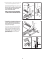
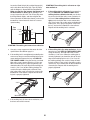
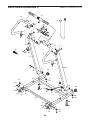
6. See the left inset drawing. Identify the outer
side of the remaining Frame Spacer (79).
6
Hold the Frame Spacer (79) between the Left
Upright (77) and the Lift Frame (65), with the
outer side of the Frame Spacer facing the
Left Upright. Attach the Left Upright to the Lift
Frame with a 3/8" x 2 1/2" Bolt (1), a 3/8"
Washer (10), and a 3/8" Nut (13); do not
tighten the Bolt yet.
77
79
10
1
13
65
79
Outer
Side
Inner
Side
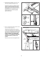
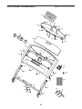
7. Have a second person hold the console assembly near the Right Upright (78).
7
Connect the wire harness on the console assembly to the Upright Wire (74) as shown in the
inset drawing. The connectors should slide together easily and snap into place. If they do
not, turn one connector and try again. IF YOU
DO NOT CONNECT THE CONNECTORS
PROPERLY, THE CONSOLE MAY BECOME
DAMAGED WHEN YOU TURN ON THE
POWER.
Remove the wire tie from the Upright Wire (74).
1
13
10
79
65
Console Assembly
Wire
Harness
78
9
77
74
Wire
Tie
74