1
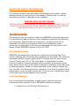
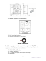
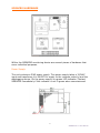
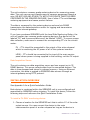
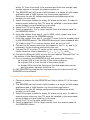
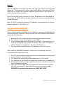
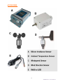
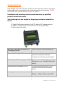
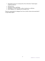
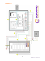
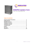
TABLE OF CONTENTS
Important Safety Information
2
Getting Started
2
SORAPRO Hardware
4
Installation Overview
5
Network Commissioning
8
Installation Checklist
10
Accessories
11
Troubleshooting
12
Technical Data
15
Support
16
Warranty
17
Appendix A
18
1
SORAPRO VC1.1 User Manual
IMPORTANT SAFETY INFORMATION
This manual contains important safety and operating information. Please
read and follow the instructions in this manual. Failure to do so could be
hazardous and result in damage to the hardware.
DANGER! HIGH VOLTAGE HAZARD
INSTALLATION OF ANY SORAPRO IS FOR QUALIFIED PERSONNEL ONLY. TO
AVOID ELECTRICAL SHOCK, DO NOT INSTALL OR SERVICE ANY SORAPRO
HARDWARE UNLESS YOU ARE A QUALIFIED TO DO SO
GETTING STARTED
This guide will help you properly install the SORAPRO monitoring equipment.
It is important to read through all of the installation steps prior to installing
any equipment. Read through the instructions, visualize where all the
equipment will need to be installed and do a soft installation before
mounting any equipment. If you do not understand the instructions in full,
please contact SORAPRO Support at 609-807-8307.
How SORAPRO Works:
SORAPRO was developed to be easy to install while providing Real Time
energy metering and monitoring from anywhere on the planet. The metering
equipment gathers revenue grade (ANSI C12) data from the site through
Current Tranformers (CT’s). This information is transferred to remote
servers through an internet gateway and is processed for accuracy before
being stored. Once stored, this data is analyzed to establish if the solar array
is working properly, based on criteria specified by the installer through the
user interface. Any discrepancies are reporting in real time to specified users
as warning or errors through email alerts. The errors will continuously report
to the users until the discrepancies are rectified.
Inside this Package:
Prior to commencing installation, please confirm that the following
components were received in your SORAPRO installation package.
1. Hinged-Cover Lift-Off Type 3R Enclosures
2
SORAPRO VC1.1 User Manual
2. Metering equipment (pre-assembled)
3. Wall mounting hardware
4. Current Transformers (1 per phase)
Current Transformer
The following equipment is also required to complete the SORAPRO
installation. Manufacturer of each component will vary depending on the
equipment specified for the solar installation.
1.
2.
3.
4.
3-Pole 5A Circuit Breaker
14 AWG, 600V wire
¾” Conduit (or larger) with Liquid-Tite fittings
CAT5 cable
3
SORAPRO VC1.1 User Manual
SORAPRO HARDWARE
Within the SORAPRO monitoring device are several pieces of hardware that
serve individual purposes.
Power Supply:
The unit contains a 50W power supply. This power supply takes a 120VAC
input and transforms it to 24VDC for supply to the revenue meter(s) and the
datalogging device. On the power supply is a green LED indicator. Contact
SORAPRO immediately if this indicator is not lit green when commissioned.
4
SORAPRO VC1.1 User Manual
Revenue Meter(s):
The unit contains a revenue grade metering device for measuring power
data. The unit uses current transformers to measure amperage through a
wire. DO NOT USE ANY OTHER CT’s WITH THIS DEVICE THAN THE ONES
CONTAINED IN THE SORAPRO PACKAGE. Use of other CT’s could damage
metering equipment and cause product failures.
The data is measured by the metering device and send via RS485
transmission the data acquisition center for logging and transmission
through the internet gateway.
If you have purchased SORAPRO with the Load Side Monitoring Option, the
unit will contain two revenue grade metering devices. One device will be
labeled “PV” and the second device will be labeled “LOAD”. To ensure proper
data collection, make sure to connect the corresponding CT’s to the correct
meter.
PV – CT’s should be connected to the output of the solar subpanel
which is combining the AC power of all of the systems inverters.
LOAD – CT’s should be connected to the input of the main service
panel where power is being supplied to the building, not the PV output.
Data Acquisition Server:
The unit contains one data acquisition server and can support up to 32
RS485 devices. This server collects data from the connected devices. The
data is time stamped and stored in onboard memory. Using an Ethernet
connection, this data is pushed to SORAPRO data servers through an
internet gateway using HTTP protocol.
INSTALLATION OVERVIEW
See Appendix A for a Quick Installation Guide.
Each device in contained within the SORAPRO unit is pre-configured and
assembled by SORAPRO before shipping. To install the device, follow the
following steps and reference the Quick Installation Guide.
To install a PV ONLY monitoring device:
1. Choose a location for the SORAPRO unit that is within 10’ of the solar
output source. You may connect the device to the main
interconnection panel or a solar subpanel as long as the device is
5
SORAPRO VC1.1 User Manual
within 10’ from the source to be metered and there are enough open
breaker spaces to connect the proper breaker to.
2. The SORAPRO unit will need a 2p5A breaker in a single, or split phase
application and a 3p5A breaker in a three phase application.
Determine the site AC voltage configuration and determine which
breaker you will need.
3. Install the proper breaker to supply AC power to the unit. In order to
ensure proper metering, the CT’s must be installed in the same panel
as the breaker you are installing in this step.
4. Install the CT’s on the solar output wires.
5. Install a watertight, 3/4”or larger conduit from the breaker panel to
the SORAPRO device.
6. Using the conduit from step 5, run 14 AWG, solid, copper wire from
the breaker panel to the SORAPRO device.
7. Using the conduit from step 5, run the CT wires from the breaker panel
to the SORAPRO device. The SORAPRO device will come standard with
10’ leads on the CT’s. Loop any excess wire; do not cut it off.
8. Connect the AC supply wire from the breaker to the V1, V2, and V3 (if
necessary) to the terminal block within the unit.
9. Connect the CT wire the CT inputs on the metering device. These
inputs should be clearly labeled as I11, I12, I21, I22, I31, and I32
10. Connect the Ethernet (LAN) wire to the port labeled “Ethernet Port” on
the bottom of the Data Acquisition device.
11. Turn on power to the SORAPRO device and ensure the following:
a. A green LED is lit on the top of the metering device.
b. A green LED is lit on the top of the power supply.
c. Amber LEDs should be flashing on the data acquisition server
and the power indicator should be lit.
12. Call SORAPRO to complete the commissioning of the device with the
SORAPRO online software.
To install a PV and LOAD monitoring device:
1. Choose a location for the SORAPRO unit that is within 10’ of the main
panel.
2. The SORAPRO unit will need a 2p5A breaker in a single, or split phase
application and a 3p5A breaker in a three phase application.
Determine the site AC voltage configuration and determine which
breaker you will need.
3. Install the proper breaker to supply AC power to the unit. In order to
ensure proper metering, the CT’s must be installed in the same panel
as the breaker you are installing in this step.
4. Install the CT’s on the solar output wires.
5. Install a watertight, 3/4”or larger conduit from the breaker panel to
the SORAPRO device.
6
SORAPRO VC1.1 User Manual
6. Using the conduit from step 5, run 14 AWG, solid, copper wire from
the breaker panel to the SORAPRO device.
7. Using the conduit from step 5, run the CT wires from the breaker panel
to the SORAPRO device. The SORAPRO device will come standard with
10’ leads on the CT’s. Loop any excess wire; do not cut it off.
8. Connect the AC supply wire from the breaker to the V1, V2, and V3 (if
necessary) to the terminal block within the unit.
9. Connect the PV CT wires the PV CT inputs on the metering device.
These inputs should be clearly labeled as PV: I11, I12, I21, I22, I31, and
I32
10. Connect the LOAD CT wires the LOAD CT inputs on the metering
device. These inputs should be clearly labeled as LOAD:I11, I12, I21, I22,
I31, and I32
11. Connect the Ethernet (LAN) wire to the port labeled “Ethernet Port” on
the bottom of the Data Acquisition device.
12. Turn on power to the SORAPRO device and ensure the following:
a. A green LED is lit on the top of the metering device.
b. A green LED is lit on the top of the power supply.
c. Amber LEDs should be flashing on the data acquisition server
and the power indicator should be lit.
13. Call SORAPRO to complete the commissioning of the device with the
SORAPRO online software.
7
SORAPRO VC1.1 User Manual
NETWORK COMMISSIONING
Basic Network Configuration
The IP address of the AcquiSuite™
server can be implemented using one of
two methods. Check with the network
administrator to determine which
method applies. By default the server
is configured for Dynamic Host
Configuration Protocol (DHCP).
Static IP address - this is a fixed IP
address which is assigned by a
network administrator and configured
into the AcquiSuite.
Dynamic Host Configuration Protocol
(DHCP) address - this process
assigns an IP address dynamically to
the AcquiSuite when it is connected
to the network from a host DHCP
server
For Static IP address you will need
the following information from the
network administrator.
You will need the following information
from your network administrator: The
addresses will be in the form of
“###.###.###.###”), where “#”
refers to the numbers 0 to 9.
IP Address ___.___.___.___
Network Mask ___.___.___.___
Gateway ___.___.___.___
DNS Server ___.___.___.___
DNS Server 2 ___.___.___.___
HTTP Proxy _____________
Proxy Server Port: _________
8
SORAPRO VC1.1 User Manual
Static IP Address Setup:
Step 1:
LCD display, press and hold the menu (top) button on the server for several
seconds and the message should appear. To change the IP address to the
static address assigned by the network administrator, do the following:
A. Press the menu (top) button once to get the TCP/IP configuration menu
[Main Menu]
TCP/IP Config
B. Press the select (bottom) button twice to get the IP config menu:
[TCP/IP Config]
IP Address
C. Press the select button again to see the IP address menu:
[IP Address]
192.168.40.50
D. At this point, the cursor on the display will be blinking on the first number
in the IP address on the second line.
E. To change the number, press the menu (top) button and the display will
cycle through the digits 0-9 as well as “.”. Once the correct digit is
displayed, press the select (lower) button to advance to the next digit and
repeat the process until all the digits are correct.
F. Once the IP address on the AcquiSuite matches the assigned IP address,
press the select (bottom) button once more to return to the main TCP/IP
menu.
Step 2:
Set the netmask, gateway, and DNS server(s) addresses using the same
technique as shown above. The only change is that after Step B, press the
menu (top) button multiple times to see the netmask, gateway, and DNS
setup menu, then push the select button to set the option.
Note: If DHCP configuration is selected, the IP, netmask, gateway, and dns
server addresses will be obtained automatically. Simply select the “Enable
DHCP” from the first TCP/IP configuration menu.
9
SORAPRO VC1.1 User Manual
Step 3:
After the address information has been set, you must reboot the AcquiSuite.
Select the "(Previous Menu)" option after step B above. The menu will then
state that the AcquiSuite must be rebooted to take effect. Press 'select' to
allow the AcquiSuite to reboot.
Once the AcquiSuite has rebooted, the new IP address will be displayed on
the console. If DHCP addressing was specified, the server assigned address
will be displayed.
Note: if DHCP is unable to obtain an IP address, the AcquiSuite will use the
fallback address of 192.168.0.100.
INSTALLATION CHECKLIST
Three –phase systems are often to be installed in commercial buildings with
secured computer networks. Always contact the local network administrator
and verify the following:
1. Network Port 80 is open for both incoming and outgoing signals
2. The network router is configured to use DHCP.
3. If the network cannot be configured to use DHCP, the AcquiSuite unit
must be configured with a static IP address. See “Static IP Address”
under “Network Configuration” for more information.
4. The AcquiSuite should display its IP address on the LCD screen.
After installing SORAPRO hardware, make sure the following has been
completed before leaving the site:
1. The CT’s are installed on the correct lines and that they are facing the
correct direction of current flow.
2. The AcquiSuite is displaying kW readings on the LCD screen.
3. The readings on the AcquiSuite make sense under current conditions.
4. All accessories that you have installed have been installed according to
their installation manuals.
5. After you have verified that the installation has been done correctly
and that the network is sending and receiving information, call
SORAPRO to activate the device at (609) 807-8307
10
SORAPRO VC1.1 User Manual
ACCESSORIES
11
SORAPRO VC1.1 User Manual
TROUBLESHOOTING
Line voltages up to 600 VAC are present on the input terminals of the device
and throughout the connected line circuits during normal operation. THESE
VOLTAGES MAY CAUSE SEVERE INJURY OR DEATH.
Installation and servicing must be performed only by qualified,
properly trained personnel.
The following tools are helpful in diagnosing hardware installation
issues:
1. Digital Multimeter capable of mV AC and mA AC measurements.
2. Clamp on Amp meter to verify current in line (if possible).
3. Basic electrician tools.
The “Alive” light does not come on or
LCD display it not lit.
Verify connection on the terminal block.
Ethernet Link/Act light off
Inspect the cat5 cable for damage. Make
sure the colored wires inside the
connectors are all in the correct location.
Failed to upload files displayed on LCD
Verify the internet link/act light next to the
Ethernet port is on. The light will blink with
activity.
Unknown device displayed on LCD
The AcquiSuite takes between 2 and 5
minutes to detect the devices after a
reboot.
Alarm light blinks
Contact technical support at 609-807-8307
Monday – Friday from 8am to 6pm EST.
12
SORAPRO VC1.1 User Manual
Troubleshooting steps for Elkor WattsOn
WattsOn Meters calibrated for use with 5A CTs have special precautions that
must be taken. NEVER disconnect a 5A CT without shorting it first. These
CTs are capable of producing very high voltages and arcing when not
shorted, and as a result may cause serious injury or death!
Always ensure that 5A CTs are shorted via a shorting block, or that
power to the circuit which the CT is installed on is off before
disconnecting from the meter.
WattsOn meters with 5A inputs may be identified by the part number (ie:
WattsOn-1100-5A), or by the yellow sticker on the face of the unit as below:
Before commencing other troubleshooting steps, ensure that the WattsOn is
receiving a proper power supply. Power to the WattsOn is provided by to the
upper left (black) plug in two-position connector.
The green Power LED should illuminate when the WattsOn is receiving
power, however note that the LED will continue to be illuminated even
during low voltage conditions. That is, the LED is not an indication of
WattsOn "sanity" or "operation", but rather that power is simply available.
Note that voltages can sag when other equipment is powered on, especially
when using a small VA control transformer. Therefore, it is best to verify the
input voltage using a DMM, on the terminals of the black plug-in power
connector to ensure that the proper voltage is present.
The Red DIAG (diagnostic) LED has a variety of functions. Depending on the
state of the LED, it can signify a number of conditions. The table below
summarizes the LED states and related conditions:
13
SORAPRO VC1.1 User Manual
LED State Condition
To test for WattsOn functionality, it is best to connect power and disconnect
voltage inputs. In this configuration, the RED LED should flash rapidly. This
is an indication of proper operation.
During normal measurement operation (i.e. voltage inputs above 25VAC),
the DIAG LED should be OFF. If the LED stays ON constantly, or turns on an
off erratically, it is an indication of reverse power detection. This condition
arises when the SUM of the real power (watts) in all three phases is
negative. Please note however, in a three-phase system (assuming balanced
phases), if only one of the phases is reversed, the NET will continue to be
positive.
14
SORAPRO VC1.1 User Manual
TECHNICAL DATA
15
SORAPRO VC1.1 User Manual
SUPPORT
We encourage your feedback. Please contact us by mail at:
Future Solutions Technologies, LLC
120 Route 156
Yardville, NJ 08620
Phone Support is available between the hours of 8:00AM and 6:00PM EST.
For phone support, please call:
(609) 807-8307 (Phone)
(609) 888-3971
(Fax)
Email Support is also available at:
[email protected]
Copyright 2012 Future Solutions Technologies, LLC. All rights reserved.
No part of this document may be reproduced, stored in a retrieval system,
or transmitted, in any form or by any means, electronic, mechanical,
photographic, magnetic or otherwise, without the express written consent of
Future Solutions Technologies, LLC.
Future Solutions Technologies, LLC does not make representations, express
or implied, with respect to this documentation or any of the equipment
and/or software it may describe, including any implied warranties of utility,
merchantability, or fitness for any purpose. All such warranties are expressly
disclaimed. Neither Future Solutions Technologies, LLC, nor its distributors
or dealers shall be liable for any indirect, incidental, or consequential
damages under any circumstances.
The exclusion of implied warranties may not apply in all cases under some
statutes, and thus the above exclusion may not apply.
Specifications are subject to change without notice. Every attempt has been
made to make this document complete, accurate, and up to date. Readers
are cautioned that Future Solutions Technologies, LLC, reserves the right to
make changes without notice and shall not be responsible for any damages,
including indirect, incidental or consequential damages, caused by reliance
on the material presented, including, but not limited to omissions,
typographical errors, arithmetical errors or listing errors in the content
material.
Future Solutions Technologies, LLC
120 Route 156
Yardville, NJ 08620 U.S.A
16
SORAPRO VC1.1 User Manual
WARRANTY
5 Year Warranty
A five year warranty applies to the following products: VR11, VC11, VC21.
Extended Warranty
An extended 5 year warranty can be purchased for any device with a 5 Year
Standard warranty. This extended warranty is an extension of 5 years on the
Standard Warranty, from the date of the original warranty period.
Please contact the SORAPRO service line at (855)SORAPRO for more details
regarding the extended warranty.
The Standard Warranty covers any repair or replacement costs incurred
during the warranty period, beginning on the device’s purchase date, subject
to the following conditions.
Warranty Conditions
If after contacting SORAPRO for support it has been determined that a
device is defective, one of the following services will be selected by Future
Solutions Technologies, will be performed at no charge for materials or labor
costs:
•
•
Repair at Future Solutions Technologies
Exchange for an equivalent Replacement Device
In the event of receipt of a Replacement Device, the warranty will continue
on the new device from the original purchase date of the defective device.
The defective device should be packaged in the same packaging and
returned to Future Solutions Technologies. If the defective device is not
received by Future Solutions Technologies with 5 business days, charges for
the Replacement Device will apply.
Please contact support at (855)SORAPRO with questions regarding
potentially defective devices.
Warranty Exclusions
The following will result in Warrant Exclusions:
•
•
Incorrect installation
Tampering with pre-configured components
17
SORAPRO VC1.1 User Manual
•
•
•
•
•
Attempted repairs not conveyed by Future Solutions Technologies
support personnel
Incorrect use
Improper device ventilation
Installation in direct sunlight, without optional sun deflector
Force Majeure (i.e. lightning, fire, animals, etc)
Claims for compensation for damages due to loss of profits or due costs are excluded if
no legal liability applies.
18
SORAPRO VC1.1 User Manual
APPENDIX A
19
SORAPRO VC1.1 User Manual