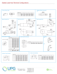
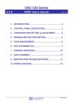
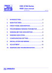
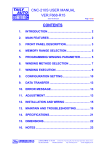
1
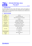
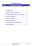
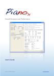
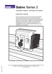
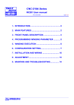
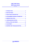
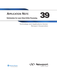
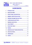
CNC-110STD C-120 User's manual (DOC NO:050523) 1. INTRODUCTION .................................................... 2 2. FEATURES............................................................. 2 3. FRONT PANEL ...................................................... 2 4. SPREADING PARAMETER SETTING .................. 3 5. SPREADING OPERATION .................................... 3 6. CONFIGURATION SETTING ................................. 4 7. INSTALLATION AND WIRING............................... 5 8. DIMENSIONS ......................................................... 7 έᚊཝҋજ̼ѣࢨ̳Φ TAILY AUTOMATION CO.,LTD. 1 2 CNC-110STD C-120 User's manual 1. INTRODUCTION CNC-110STD synchronous spreading controller, CNC-110STD IS an integrated design device, putting micro controller, step motor diver and power supply circuits into one control box, simultaneously achieving size reduction, high performance and low cost. C120 program edition is design for synchronous spreading device, to spread wire, cable, yarn, and coil. 2. Features Microprocessor design, easy for program-setting handling. Non-battery design, using EEPROM for saving memory and can retain it for 10 years. Build-in step motor drive circuit for guiding traverse, direct to drive two phases 2.0A step motor. With power failure protect function, can continue the unfinished work after power restored. Power source AC100V~AC240V 100w MAX. 50/60Hz. 3. FRONT PANEL Key pad Display ~ ĈEntering numerical values. STEP ĈItem display. Ĉ parameter setting. TURNS:Data display. ĈFunction select . ĈEnter. ĈReset. έᚊཝҋજ̼ѣࢨ̳Φ TAILY AUTOMATION CO.,LTD. Indicator L.S.ĈNo function. H.S.ĈNo function. BRAKE ĈNo function. 3 CNC-110STD C-120 User's manual 4. Spreading parameter setting The CNC-110STD with three items of spreading parameter: [1]:Shift;To set the start spreading position for guiding traverse. Setting range :[000.00~999.99]mm。 [2]:Width;To set the separating region of guiding traverse [000.00~999.99]mm。 Setting range:[000.00~999.99]mm。 [3]:Pitch;To set the separating clearance between turns. Setting range [0.000~99.999]mm. In ready mode, press to set the spreading parameters. The item display shows [1], and the data display shows Starting position setting value [xxx.xx], press numerical keys to change the value, then press to next item, follows this procedure to finish all three items parameter set, then press again, back to the ready mode. For example: Shift =10.30mm、Width =120.50mm、Pitch=35.500mm The setting procedure as follow: 。 5. Spreading operation After power on, the CNC-110STD controller will automatically get into ready mode, in this mode when spindle is rotating, the counting sensor will send the spreading signal to the controller, and the guiding traverse will according to the setting value to spreading automatically. ※If the spindle is rotating in opposite direction, the guiding traverse will not move and the display gleam warning. Each time, after finish a products spreading, have to do reset process once and then to spreading for a new product. Reset process Press or the reset input signal (on the back panel CN1 connector) is low lever, the guiding traverse will move to the home position to do the position corrective action, and then move to the starting position. Position display During spreading, the data display will shows the actually position of the guiding traverse, the positions value is use the home position as the basis.。 Position compensates to compulsive moving the guiding traverse homeward, and press In ready mode, press to compulsive moving the guiding traverse in opposite direction, the position compensates action will not changed the actually position display value. έᚊཝҋજ̼ѣࢨ̳Φ TAILY AUTOMATION CO.,LTD. 4 CNC-110STD C-120 User's manual 6. Configuration setting 6.1. Moving increment In ready mode, press to set the guiding traverse moving increment, the item display shows [F], and data display shows [0 x.xx], press numerical keys to change the value, then press to finish setting, setting range [0.00~9.99] How to calculate the guiding traverse moving increment Moving increment=(Screw pitch × Gear ratio ÷ 4) Example: Screw pitch=5mm、Gear ratio=1.6(step motor side ÷ screw side) Moving increment=5 ×1.6 ÷ 4 = 2.00 Reference table Screw pitch Gear ratio (step motor side0screw side) 1.6/1 2/1 3.2/1 0.8/1 1/1 4/1 8/1 2.00mm 0.40 0.50 0.80 1.00 1.60 2.00 4.00 4.00mm 0.80 1.00 1.60 2.00 3.20 4.00 8.00 5.00mm! 1.00 1.25 2.00 2.50 4.00 5.00 8.00mm 1.60 2.00 3.20 4.00 6.40 8.00 10.00mm 2.00 2.50 4.00 5.00 8.00 16.00mm 3.20 4.00 6.40 8.00 6.2. Moving speed To set the moving speed for the guiding traverses moving to home position and starting position. In ready mode, press to set the moving speed, the item display shows [F], and data display to finish setting, shows [1 xx], press numerical keys to change the value, then press setting range [00~99], 550PPS~3000PPS. έᚊཝҋજ̼ѣࢨ̳Φ TAILY AUTOMATION CO.,LTD. 5 CNC-110STD C-120 User's manual 7. Installation and wiring 7.1. Counting system assembly (unit=mm) The counting disc and the sensor must assembly as below, otherwise it will count improperly. Counting disc Zeroing disc Winding spindle Zeroing sensor Max. 1.0 Min. 3.0 Counting sensor ※ The CNC-110STD do not need to use the Zeroing disc. 7.2. Home sensor assembly (unit=mm) HOME SENSOR must be assembly as below, otherwise a fault may occur. Screw Guiding traverse shaft Interrupter Max. 10.0 Min. Min. Max. έᚊཝҋજ̼ѣࢨ̳Φ TAILY AUTOMATION CO.,LTD. 3.0 1.0 1.0 Home sensor 6 CNC-110STD C-120 User's manual 7.3. Wiring diagram CN1 CN2 CN3 CN4 DC12V 40mm FAN SERIAL CNC-110STD 999999999 POWER AC 110~240V 50/60HZ 100W TAILY AUTO 台麗電自動化有限公司 TAILY AUTOMATION MODEL 3P 4P 5P CN1 CN2 CN3 CN1 1 BK AC 2 GN Earth 3 W AC (0.5mm 3C 180cm) CN2 1 2 3 4 R W BK GN DB-15P CN4 CN3 1 R, OR +24V 2 W PHA 3 GN PHB HOME 4 Y 0V 5 BK,BL (24AWG 9C 100cm) A AB B- (0.5mm 4C 200cm) CN4 1 W RESET 2 3 BK 0V 4 5 1 3 RESET RESET COM(0V) (0.5mm 2C 200cm) Home Sensor HSB-01A 5 BL 4 Y 1 OR (A) (A-) (B) (B-) 1 1 2 3 4 Step motor AC 110~240V 2 phases 2.0A Counting sensor 5 3 2 1 BK GN W R CNTB-03B 1 7.4. Accessories Item Name Qty. 1 CN1 AC power connection cable. 1 2 CN2 step motor connection cable. 1 3 CN3 Sensors connection cable. 1 4 CN4 15P Input signal connection cable. 1 5 CNTB-03B Counting sensor 1 6 HSB-01A Home sensor 1 7 Counting DISC 1 έᚊཝҋજ̼ѣࢨ̳Φ TAILY AUTOMATION CO.,LTD. 7 CNC-110STD C-120 User's manual 174.0 8.0 131.5 59.0 72.5 8.0 10.0 90.0 8. Dimensions CNC-110STD 3.5 22.0 R10.0 51.0 3.5 14.5 3.1 x 4 22.0 15.0 14.5 51.0 3.0 R1 7.0 7.0 10.0 12.0 9.0 13.0 1.5 CNTB-03B Counting sensor .0 R28 3.2 x 2 3.2 x 2 10.0 6.0 6.0 5.0 10.0 1.5 HSB-01A Home sensor έᚊཝҋજ̼ѣࢨ̳Φ TAILY AUTOMATION CO.,LTD. 71ƶ 71ƶ COUNTING DISC