1
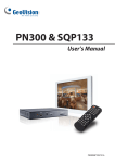
PN300 & SQP133 User’s Manual PN300SQP133V10-A © 201 GeoVision, Inc. All rights reserved. Under the copyright laws, this manual may not be copied, in whole or in part, without the written consent of GeoVision. Every effort has been made to ensure that the information in this manual is accurate. GeoVision, Inc. makes no expressed or implied warranty of any kind and assumes no responsibility for errors or omissions. No liability is assumed for incidental or consequential damages arising from the use of the information or products contained herein. Features and specifications are subject to change without notice. Note: no SD/SDHC card slot or local storage function for Argentina. GeoVision, Inc. 9F, No. 246, Sec. 1, Neihu Rd., Neihu District, Taipei, Taiwan Tel: +886-2-8797-8377 Fax: +886-2-8797-8335 http://www.geovision.com.tw Trademarks used in this manual: GeoVision, the GeoVision logo and GV series products are trademarks of GeoVision, Inc. Windows and Windows XP are registered trademarks of Microsoft Corporation. September 2013 Contents Preface ...............................................................................................................................vi Compatible Firmware and Software Versions ...................................................................vii Chapter 1 Introduction ........................................................................................................1 1.1 Features .....................................................................................................................1 1.2 Packing List ................................................................................................................1 1.2.1 PN300 .........................................................................................................1 1.2.2 SQP133.......................................................................................................1 1.3 Options .......................................................................................................................2 1.4 Overview ....................................................................................................................3 1.5 PN300 .........................................................................................................3 1.4.2 SQP133.......................................................................................................5 The IR Remote Control ..............................................................................................7 Chapter 2 2.1 1.4.1 Getting Started ...................................................................................................9 Connecting the Device ...............................................................................................9 2.1.1 Connecting the PN300 ................................................................................9 2.1.2 Connecting the SQP133 ...........................................................................10 2.2 Installing Wall Mount ................................................................................................ 11 2.3 Installing VESA Monitor Mount.................................................................................12 2.4 Playing the Slideshow ..............................................................................................13 Chapter 3 System Setup ...................................................................................................14 3.1 The Setup Menu.......................................................................................................14 3.2 Setting Video Output and Resolution .......................................................................15 3.3 Setting Slideshow Display Effect..............................................................................16 3.4 Looking Up Device Information ................................................................................17 3.5 Setting the Time .......................................................................................................18 3.6 3.5.1 Setting the System Time ...........................................................................18 3.5.2 Setting the Time Zone ...............................................................................18 Setting the Network ..................................................................................................19 3.6.1 Wired Network Connection .......................................................................19 3.6.2 Wireless Network Connection ...................................................................20 3.7 Setting the Device Name..........................................................................................21 3.8 Copying Files from the USB Storage Device............................................................21 3.9 Upgrading the Firmware...........................................................................................22 3.10 Restoring to Factory Default Settings.....................................................................23 Chapter 4 4.1 Content Designer .............................................................................................24 Minimum System Requirements ..............................................................................24 iii 4.2 Installing the Content Designer ................................................................................25 4.3 The Menu Bar...........................................................................................................26 4.4 Creating a Project.....................................................................................................27 4.5 4.4.1 Create a Screen Layout ............................................................................27 4.4.2 The Main Screen.......................................................................................29 4.4.3 Assign Content to Zones...........................................................................31 4.4.4 Preview and Save Screen Layout .............................................................35 Playing the Project on PN300 or SQP133................................................................36 Chapter 5 Content Schedule.............................................................................................37 5.1 Installing the Content Schedule................................................................................37 5.2 Setting the Content Schedule...................................................................................38 Chapter 6 CMS Lite............................................................................................................45 6.1 Software License......................................................................................................46 6.2 Installing the CMS Lite .............................................................................................47 6.3 Connecting the Devices to CMS Lite........................................................................48 6.4 The Main Screen ......................................................................................................49 6.5 Uploading Video and Image Files ............................................................................51 6.6 Uploading the Scenario ............................................................................................52 6.7 Uploading the Schedule ...........................................................................................53 6.8 Uploading the Firmware ...........................................................................................54 6.9 Uploading the Scrolling Ticker..................................................................................55 6.10 Changing the Device Name ...................................................................................56 Chapter 7 7.1 CMS Server .......................................................................................................57 System Requirements ..............................................................................................58 7.1.1 Minimum System Requirements ...............................................................58 7.1.2 Software License.......................................................................................58 7.2 Installing CMS Server...............................................................................................59 7.3 Connecting the Devices to CMS Server...................................................................60 7.4 Starting CMS Server.................................................................................................61 7.4.1 7.5 iv List of Menu Options .................................................................................63 Getting Started .........................................................................................................64 7.5.1 Preparing the Package..............................................................................64 7.5.2 Transferring the Package ..........................................................................65 7.5.3 Uploading the Package .............................................................................67 7.5.4 Revising the Package ...............................................................................69 7.6 Applying the Scrolling Ticker ....................................................................................70 7.7 Applying the RSS Feed ............................................................................................71 7.8 Planning Device Group ............................................................................................72 7.9 Arranging the Loop Video.........................................................................................74 7.10 Information .............................................................................................................76 7.10.1 Device Information ..................................................................................76 7.10.2 System Information .................................................................................77 7.10.3 User Information......................................................................................77 7.10.4 Package Information ...............................................................................78 7.11 Device Setup ..........................................................................................................79 7.12 Event Query ...........................................................................................................80 7.13 7.14 7.12.1 Behavior Log Query ................................................................................80 7.12.2 Behavior Log Analysis.............................................................................81 7.12.3 Device Event Query ................................................................................82 7.12.4 Device Event Analysis (Counts) ..............................................................83 7.12.5 Device Event Analysis (Elapsed Time)....................................................84 7.12.6 Play Count Analysis ................................................................................85 Server Setting.........................................................................................................87 7.13.1 User Account...........................................................................................87 7.13.2 Network Setting.......................................................................................88 7.13.3 Email Service ..........................................................................................89 7.13.4 Package Management ............................................................................91 Upgrading the Firmware.........................................................................................92 Chapter 8 Dynamic DNS....................................................................................................93 8.1 Installing the Dynamic DNS......................................................................................93 8.2 Registering Domain Name .......................................................................................94 8.3 Starting Dynamic DNS..............................................................................................96 Specifications .......................................................................................................................97 PN300 ...............................................................................................................................97 SQP133 ............................................................................................................................98 Appendix ..............................................................................................................................99 Definitions of Folder Names..............................................................................................99 v Preface Welcome to thePN300 & SQP133 User’s Manual. The PN300 & SQP133 are devices that play back slideshows edited or managed by GeoVision’s software such as Content Designer, Content Schedule, CMS Lite and CMS Server. This Manual is designed for the following models, firmware, and software version: Hardware Model Firmware Version PN300 1.0.5.0 SQP133 1.0.5.0 Software vi Model Software Version Content Designer 1.0.5.0 Content Schedule 1.0.3.0 CMS Lite 1.0.3.0 CMS Schedule 1.0.3.0 Compatible Firmware and Software Versions The PN300 / SQP133 / SQP110 Series are compatible with CMS Server / CMS Lite / Content Designer. See the following compatible versions. PN300 / SQP133 SQP110 Series CMS Server / CMS Lite V1.0.3.0 V1.0.5.0 N/A CMS Server / CMS Lite V1.0.2.0 or V1.0.4.0 or earlier V1.0.3.0 or earlier Content Designer V1.0.5.0 V1.0.5.0 N/A Content Designer V1.0.4.0 or earlier V1.0.4.0 or earlier N/A earlier vii 1 Chapter 1 Introduction Introduction The PN300 and SQP133 are digital media players designed to deliver uninterrupted playback of Digital Signage presentations. 1.1 Features Multimedia support Video resolution up to 1080p and Video outputs of HDMI and VGA (PN300 only) Panel resolution of 1280 x 800 (SQP133 only) Built-in speaker (SQP133 only) SD card and USB storage Content Schedule and Content Designer Content Management System (CMS Server and CMS Lite) IR remote control Wireless connectivity (GV-WiFi USB Adapter required) 1.2 Packing List 1.2.1 PN300 1. PN300 device × 1 2. IR remote control × 1 3. AC/DC adapter × 1 (12 V, 3 A, 36 W) 4. Power cord x 1 5. Software DVD x 1 1.2.2 SQP133 1. SQP133 device × 1 2. IR remote control × 1 3. Magnetic hinge x 1 4. Screw x 4 5. AC/DC adapter × 1 (12 V, 3 A, 36 W) 6. Power cord x 1 7. Software DVD x 1 1 1.3 Options Optional devices can expand the capabilities and versatility of your PN300/SQP133. Contact your dealer for more information. Options Wall Mount Kit Detail The Wall Mount Kit is used to mount the PN300 to the wall. VESA Monitor-Mount Kit L-type brackets x 2 Small screws x 4 The VESA Monitor Mount Kit is used to mount the PN300 to the back of a VESA monitor. GV-WiFi USB Adapter VESA monitor mount bracket x 1 L-type brackets x 2 Large screws x 4 Small screws x 8 The GV-WiFi USB adapter is a plug-and-play device that provides wireless connectivity to GeoVision IP devices. The GV-WiFi USB Adapter complies with IEEE802.11 b/g/n (Draft 3.0) standards for wireless networking. Internal GV-USB Dongle for The USB dongle can provide the Hardware Watchdog CMS Lite and CMS Server function to the system by restarting the computer when Windows crashes. You need to connect the dongle internally on the motherboard. SD Card (4 GB, Class 4) The SD Card is used for local storage and firmware upgrade. 2 1 Introduction 1.4 Overview This section identifies the components of the PN300 and SQP133. 1.4.1 PN300 Front View Figure 1-1 No. Name 1 LED Indicators Function The green LED indicates the system is ready. The red LED indicates the power is supplied. Connect to a USB device for local storage of content, firmware 2 USB upgrade and GV-WiFi USB Adapter. Note the removal of the USB storage device will cause the PN300 to automatically reboot. 3 IR 4 Default Built-in IR receiver to receive the IR signals from the IR remote control. Reset the PN300 to the default factory settings. See 3.10 Restoring to Factory Default Settings. Connect to a SD card for local storage and firmware upgrade. 5 SD Card Slot Note the removal of the SD card will cause the PN300 to automatically reboot. 3 Rear View Figure 1-2 No. Name Function 1 Ethernet Connect to an Ethernet. 2 SPDIF Reserved (not enabled). 3 HDMI Connect to an HDMI supported display device. 4 VGA Connect to a VGA monitor. 5 L/R Connect to a speaker. 6 Power OFF/ON Switch the power on or off. 7 DC 12V Connect to power by using the supplied power adapter. 4 1 1.4.2 Introduction SQP133 Right Panel View 1 2 3 4 5 Figure 1-3 No. Name 1 SD Card Slot Function Connect to an SD card for local storage of content and firmware upgrade. Connect to a USB device for local storage of content, 2 USB firmware upgrade, and GV-WiFi USB Adapter. Note the removal of the USB storage device will cause the SQP133 to automatically reboot. 3 LED Indicators 4 IR 5 Ethernet The green LED indicates the system is ready. The red LED indicates the power is supplied. Built-in IR receiver to receive the IR signals from the IR remote control. Connect to an Ethernet. 5 Left Panel 1 2 3 4 5 6 7 8 9 Figure 1-4 No. Name Function 1. MENU Switch to the setup menu. 2 ENTER Enter the setup options or save the settings in the Setup Menu. 3 UP Move the cursor up. 4 DOWN Move the cursor down. 5 LEFT Move the cursor left. 6 RIGHT Move the cursor right. Press to enter the Standby mode. In the standby mode, the screen 7 STAND BY turns off to minimize power consumption. Press the key again to enter the ON mode. 8 Power OFF/ON Switch the power on or off. 9 DC 12V Connect to power using the supplied power adapter. 6 1 1.5 Introduction The IR Remote Control 1 5 2 6 3 7 4 8 9 10 Figure 1-5 No. Name Function Press to enter the Standby mode. In the standby mode, the 1 Power screen turns off to minimize power consumption. Press the key again to enter the ON mode. Numeric / Alphabetical / 2 Punctuation Marks Enter the numbers, alphabets or punctuation marks. Buttons Back to the previous page in the Setup Menu. Play the media files. 3 Back 4 Menu Control Move up, down, right and left in the Setup Menu. 5 Volume Control Increase or decrease the volume. 6 Mute Mute the volume. 7 Menu Switch to the setup menu. 7 8 OK Enter the setup options or save the settings in the Setup Menu. Switch among the 8 resolutions for PN300. Once the button is pressed, the Green LED on the front panel of PN300 will flash. Press No. 0 ~ 7 for the desired resolution within 30 seconds. Shift + 0 : VGA_640 x 480 9 Shift Shift + 4 : HDMI_480p Shift + 1 : VGA_1024 x 768 Shift + 5 : HDMI_720p Shift + 2 : VGA_1280 x 768 Shift + 6 : HDMI_1080i Shift + 3 : VGA_1366 x 768 Shift + 7 : HDMI_1080p Note the resolution switch will cause the PN300 to automatically reboot. 10 8 Search Scan for available Access Points or wireless stations when wireless network is selected. Chapter 2 Getting Started 2.1 Connecting the Device 2.1.1 Connecting the PN300 3 5 2 1 4 Figure 2-1 1. Connect a display device to VGA video connector, or HDMI connector for video and audio combined outputs. 2. Connect to a standard network cable. 3. If you use a VGA monitor, connect a speaker to L/R port for audio output. 4. Connect to power using the supplied power adapter. 5. Switch the Power button to ON. Note: 1. You can only connect the PN300 / SQP133 to one display device through the HDMI or VGA connector. The video signal will be unstable if multiple display devices are connected. 2. The default video output is set to VGA with 1024 x 768 resolutions. To change the default setting, see 3.2 Setting Video Output and Resolution. 9 2.1.2 Connecting the SQP133 Follow the steps below to connect the SQP133: Figure 2-2 1. Connect to power using the supplied power adapter. 2. Connect to a standard network cable. 3. Turn the Power switch to ON. 10 2 Getting Started 2.2 Installing Wall Mount Optionally, you can purchase the mounting plates to mount PN300 on a wall. 1. Unscrew the 4 screws on the back panel of the PN300. Figure 2-3 2. Use the 4 screws in the package to tighten the L-type brackets on the PN300. L-Type Bracket L-Type Bracket Figure 2-4 11 2.3 Installing VESA Monitor Mount Optionally, you can purchase VESA Monitor mount for installing PN300. 1. Follow steps 1 and 2 in 2.2 Installing Wall Mount to tighten the L-type brackets on the back panel of PN300. 2. Using the 4 large screws, tighten the VESA monitor mount bracket on the back of the computer monitor. Figure 2-5 3. Use the 4 small screws to tighten the PN300 and the VESA monitor mount bracket together. Figure 2-6 12 2 Getting Started 2.4 Playing the Slideshow Without any further settings, you can now play the slideshow made of video or image files. 1. Create a folder named Loop_Video in a USB storage device or a SD card. 2. Copy image or video files to the Loop_Video folder. 3. Connect the USB storage device or the SD card to the device. 4. Turn on the digital signage device. 5. By default, the local storage is SD card. If you are using a SD card, the device will repeatedly play the files at this step. 6. If you are using a USB storage, select Play Source and select USB to be the storage, press Back to return the menu, and press Back again to start playing. Note: 1. For the folder names workable on the device, see Definitions of Folder Names, Appendix. 2. By default, the image and video files are sorted by name, first in numerical and then alphabetical order. To change the sorting rule to by size or random, see Loop Mode option, 3.3 Setting Slideshow Display Effect. 13 Chapter 3 System Setup You can customize the system settings of the PN300 / SQP133. 3.1 The Setup Menu Turn on the PN300 / SQP133 and the connected display device. The setup menu with six setup options appears. Figure 3-1 Name Service Play Source Information Description Set up the video output and resolution. See 3.2 Setting Video Output and Resolution. Select the local storage and set up the slideshow display effect. See 3.3 Setting Slideshow Display Effect. Display the network information, storage information and the device firmware version. See 3.4 Looking Up Device Information. Time Adjustment Set up the system time. See 3.5 Setting the System Time. Network Set up the network. See 3.6 Setting the Network. Upgrade firmware or to copy files from the USB storage device to the SD Factory card. Select Language and Time Zone settings. See 3.5.2 Setting the Time Zone, 3.8 Copying Files from the USB Storage Device and 3.9 Upgrading the Firmware. 14 3 System Setup 3.2 Setting Video Output and Resolution To set up the video output and resolution for PN300, select Service . The following window appears. Figure 3-2 Output: Select a video output from VGA or HDMI which is supported by the display monitor. Resolution: Select a screen resolution from the following options: HDMI at 60 Hz 480p 720p 1080i 1080p VGA at 60 Hz 640 x 480 1024 x 768 1280 x 768 1366 x 768 By default, the video output is set to VGA with 1024 x 768 resolutions. Note: The video output and resolution for SQP133 cannot be changed. 15 3.3 Setting Slideshow Display Effect To set up slideshow display effect, select Play Source . The following window appears. Figure 3-3 Storage: Select a local storage from USB or SD. By default, SD card is set as local storage. Interval Time: Select the interval time to play the slideshow. The options include 1, 3, 5, 10, and 30 seconds. Transition Effect: Select the transition effect for the slideshow from the nine options: Bevel, Shutters, Blind Top Down, Circle, None, Top Down, Bottom Up, Left to Right or Right to Left. Audio Volume: Select an audio volume value. The larger the value, the louder the volume. Loop Mode: Select a playback mode for the slideshow from the three options: By Size, Random or By Name. Loop Ratio: Select Full to set the slideshow to full screen or select Default to use the setting of the slideshow. Note: The display effect will not apply to the project created using the Content Designer. 16 3 3.4 System Setup Looking Up Device Information To see the network information, storage information, current time and firmware version, select Information . The following window appears. Figure 3-4 Output: Shows the video output and resolution. Storage: Shows whether the local storage is set to SD or USB. The remaining storage space is shown in parenthesis. Network: Shows the IP address of the device. CMS IP: Shows the IP address set for connection to CMS Lite or CMS Server. Power ON/OFF: Shows whether the Power ON/OFF function is enabled or not. Current Time: Shows the current date and time. Version: Shows the firmware version of the device. 17 3.5 Setting the Time 3.5.1 Setting the System Time To set up the system time, select Time Adjustment . The following window appears. Figure 3-5 Set Local Time: Set up the date and time. Power ON/OFF: Select Yes and set up the power on and off time. For example, if you set the power on/off to 09:00/22:00, the device will automatically turn on at 9 am and turn off at 10 pm daily. 3.5.2 Setting the Time Zone To set up the time zone, select Factory and use the arrow button from the remote control to define the time. Figure 3-6 18 3 System Setup 3.6 Setting the Network You can configure the network settings of the device to establish a wired or a wireless network connection. The network connection allows you to manage the media files from a remote Content Management System (CMS). For more details on CMS Lite or CMS Server, see Chapter 6 CMS Lite or Chapter 7 CMS Server. By default, the device will be assigned an unused IP address automatically by the DHCP server when connected to the network. 3.6.1 Wired Network Connection By default, the device will be assigned an unused IP address automatically by the DHCP server when connected to the network. If the device is installed in a LAN without the DHCP server, assign a fixed IP address for network access. Figure 3-7 1. Select Network and select LAN Setting. 2. To specify a static IP address for the device, select NO in the DHCP section and enter a fixed IP address, subnet mask and DNS and gateway. 3. Press OK to save the settings and connect to the network. 19 3.6.2 Wireless Network Connection A GV-WiFi USB Dongle is required to connect the device to the wireless network. Figure 3-8 1. To establish a wireless network connection, select Network and select WLAN Setting. 2. Press the Search button to scan for available Access Points / wireless stations. 3. Select an Access Point / wireless station in the ESSID field and complete the settings below. ESSID: Shows the name of the Access Point. Press the left and right button to select an Access Point. Quality: Shows the connection quality on a scale of 1 to 100 with 100 being the highest quality. AuthMode: Select WEP Auto or WPAPSK according to the encryption setting of the Access Point. EncryMode: Select the Encryption Mode according to the encryption setting of the Access Point. Password: Type a password to match the Access Point. You can type up to 26 characters. 4. Press OK to save the settings and connect to wireless LAN. 20 3 System Setup 3.7 Setting the Device Name You can name the device by selecting Factory , and entering a name in the Location field. Figure 3-9 3.8 Copying Files from the USB Storage Device You can always insert the SD card on the PN300 / SQP133 and use a USB storage device to transfer media files to the SD card. 1. Copy the Schedule, Loop_Video or Scenario folders to the USB storage device. 2. Connect the USB storage device to the device. 3. On the setup menu, select Factory . 4. In the Copy from USB field, select the folder you want to replace: Schedule, Loop_Video or Scenario. Figure 3-10 5. Press OK. The files will be replaced after the file transfer is complete. Note: For details on the Schedule, Loop_Video and Scenario folders, see Definitions of Folder Names, Appendix. 21 3.9 Upgrading the Firmware We will periodically release the updated firmware on the website. You may also find the updated firmware from the Software DVD. 1. Copy the firmware file to the root folder of a USB storage device or a SD card. 2. Connect the local storage. 3. On the setup menu, select Factory . 4. In the Firmware Update field, select USB or SD storage that stores the firmware file. Figure 3-11 5. Press OK. The firmware upgrade runs automatically, and the device will restart after the firmware upgrade is complete. Note: 1. To upgrade the firmware through CMS Server or CMS Lite, see 6.8 Uploading the Firmware or 7.10 Upgrading the Firmware. 2. You need to allocate at least 100 MB in the device storage before upgrading the firmware. 22 3 System Setup 3.10 Restoring to Factory Default Settings To restore to default settings, follow the steps below. Note: The power should always be on during the process of loading default value. For PN300, use the default button on the device to restore default settings. 1. Press and hold the Default button (No.1, Figure 1-1) on the front panel of the PN300. The green LED will turn off after 8 seconds. Then you can release the Default button. 2. Wait until the green LED turns on. This may take about 10 seconds. 3. The process of loading default values is complete. For SQP133, use the setup menu to restore default settings. 1. On the setup menu, select Factory . 2. In the Load Default field, select Yes and select OK to confirm. Figure 3-12 23 Chapter 4 Content Designer Using the Content Designer, you can design your own digital media content. You can create a project contained with images, videos, scrolling tickers, RSS feeds or QR code for digital signage presentations. 4.1 Minimum System Requirements The minimum system requirements to install and run the Content Designer: 32-bit Windows XP / 7 64-bit Windows XP / 7 OS Supported CPU Pentium 4, 3.0 GHz RAM 1 GB HDD 80 GB Graphic Card AGP or PCI-Express, 1024 x 768 (1280 x 1024 recommended), 32-bit color DirectX 9.0c .NET Framework 3.5 24 4 Content Designer 4.2 Installing the Content Designer Follow the steps below to install the Content Designer: 1. Insert the Software DVD to your computer. It runs automatically and a window pops up. Figure 4-1 2. Select Install DirectX 9.0c and follow the on-screen instructions. 3. Select Install Microsoft .NET Framework 3.5 (Not compatible with Windows 2000) and follow the on-screen instructions. 4. Select Install Authoring Tools and then select Install Authoring Tool-Content Designer (Only for PN300 & SQP133), and follow the on-screen instructions. Figure 4-2 25 4.3 The Menu Bar 1 2 3 4 Figure 4-3 No. Name Function 1 File Create, open or export a scenario or a project. 2 Control Select a transition mode for the displayed. Add grid lines and select the color of the grid line on the 3 Windows canvas to help edit the project, or change the language setting. 4 26 About Display the version properties of the Content Designer. 4 4.4 Content Designer Creating a Project Follow the instructions below to create a project. 4.4.1 Create a Screen Layout 1. To create a project, click File on the menu bar and select New Scenario. 2. Select PN300 or SQP133 and a screen resolution. Figure 4-4 Note: The Content Designer supports the following resolutions for HDMI and VGA video outputs: HDMI at 60 Hz 480p 720p 1080i 1080p VGA at 60 Hz 640 x 480 1024 x 768 1280 x 768 1366 x 768 For HDMI 480p, select 720 x 480; for HDMI 720p, select 1280 x 720; for HDMI 1080p and 1080i, select 1920 x 1080. 3. Click the Rotation drop-down list to select 0° for the landscape display or 90° for the portrait display. Here we choose the landscape display to show you the following instructions. 27 4. Select a desired template or select Null to create your own layout. Figure 4-5 28 4 4.4.2 Content Designer The Main Screen After the screen layout is selected, the main screen appears. 4 5 6 7 8 1 2 3 9 10 Figure 4-6 No. Name Function 1 Display the location of an object (or a zone) on the layout. Overview QR: Add an object (or a zone) to include QR code. Ticker: Add an object (or a zone) to include a scrolling ticker. You can only add up to 32 scrolling tickers to a project. 2 New Object Image: Add an object (or a zone) to include an image. Video: Add an object (or a zone) to include a video file. You can only add one video file to a project. RSS feed: Add an object (or a zone) to include a RSS. You can only add one RSS to a project. Note that it is an either-or option between the Ticker and the RSS feeds. 29 3 Object Type 4 Background Image 5 Hide/Show Object Layer Type figures in the Size and Position boxes to modify the size and the location of an object (or a zone). Add a background image in PNG, BMP or JPEG format by clicking Browse. Hide or show the layer of the selected object/zone. 6 Size Enlarge (100%) or minimize (50%) the layout. 7 Layout Select Layout to edit a project. 8 Preview Select Preview to view the created project. Blue: Image files Green: Video or image files 9 Object Colors Purple: QR code Orange: Scrolling Ticker Red: RSS feeds 10 30 Resolutions Display the screen resolution and rotation degree of the project. 4 4.4.3 Content Designer Assign Content to Zones You can add new objects (zones) to the layout by clicking the New Object button and then selecting Image, Video, Ticker, RSS feed or QR. Up to 7 objects (zones) can be included in a layout, with only one video object and one scrolling ticker/RSS feeds allowed. Dragging the sides of the object (or zone) can change the position or size of objects (zones). 1. To add video or image files: A. Double-click the Video or Image object (zone) B. Click the Browse button . to browse the folder containing video or image files. Figure 4-7 C. Drag the desired video or image files to the playlist. Up to 50 video or image files can be added. You can change the order of the files on the playlist by using the arrow buttons. D. Define the interval time to play the video or image files. Click OK. 2. To add images: A. Double-click the Image object (zone) . 31 B. Click the Browse button to browse the folder containing image files. Figure 4-8 C. Drag the desired image files to the playlist. Up to 50 image files can be added. You can change the order of the files on the playlist by using the arrow buttons. D. Define the interval time in seconds to play the images. Click OK. Note: The image format supported are .PNG, .BMP and .JPEG 32 4 3. To add a scrolling ticker Content Designer : A. Double-click the Ticker object (zone). B. In the Text field, type the desired text you want to display in a ticker fashion. Figure 4-9 C. Click the button to add the text to the text list. Up to 32 tickers can be added to display in order. You can change the order of the tickers on the text list by using the arrow buttons. D. Optionally, you can change the font, background color and font size of the text. You can also select the speed and scrolling direction to display the text. E. Click OK. Note: In the portrait mode, the ticker can solely be displayed on the bottom. 4. To add a QR code : A. Double-click the QR object (zone). B. In the Text section, type the desired content you want to display in the QR code. Figure 4-10 33 C. Optionally, you can change the QR code color by clicking the Setting button or the QR object size by clicking the Scale drop-down list. D. Click OK. 5. : To add the RSS feeds A. Double-click the RSS feed object (zone). B. In the Feed URL section, click the button and select a source of news headlines from the list. Figure 4-11 C. Click the Connection button to test the selected Feed URL to find out if the news link is available. D. In the Wait Message field, type the text message to display on the device before it receives the RSS feeds. This Wait Message solely appears at the first time this function being applied. E. Optionally, you can change the font, background color and font size of the text. You can also select the speed and scrolling direction to display the text. F. In the Refresh Rate drop-down list, define how often you want to refresh the news headlines. Note: It is an either-or option for the Ticker and the RSS feeds. 34 4 4.4.4 Content Designer Preview and Save Screen Layout 1. To preview the created project, click Preview screen. on the main 2. To save the project, click File and select Output Scenario. 3. Name the project in the Scenario Name field. Click the project. to browse the location to save Figure 4-12 Note: 1. Do not use space in the Scenario Name if you want to include the scenario in a content schedule. 2. Windows Media Player is required to preview the project you created. 35 4.5 Playing the Project on PN300 or SQP133 To play the project, created using the Content Designer, on the PN300 / SQP133, follow the steps below: 1. Create a folder named Scenario in a USB storage device or a SD card. 2. Copy the project files to the Scenario folder. 3. Connect the USB storage device or the SD card to the PN300 / SQP133. 4. Turn on the display monitor and the PN300 / SQP133. 5. By default, the local storage is SD card. If you are using a SD card, the PN300 / SQP133 will play the project automatically at this step. 6. If you are using a USB storage, select Play Source and select USB to be the storage, press Back to return the menu, and press Back again to start playing. Note: 1. You can only store one project in the Scenario folder. If you store multiple projects in the Scenario folder, the PN300 / SQP133 can only play the last project. To play multiple projects, you can set up a schedule by using the Content Schedule software. See Chapter 5 Content Schedule. 2. The PN300 / SQP133 can only play the files stored in the Scenario folder if you store both the Scenario and Loop_Video folders in the storage device. To play both Scenario and Loop_Video files, you can set up a schedule by using the Content Schedule software. See Chapter 5 Content Schedule. 3. You can also upload scenario to PN300 or SQP133 using CMS Lite or CMS Server. Refer to Chapter 6 CMS Lite or Chapter 7 CMS Server for more details. 36 5 Chapter 5 Content Schedule Content Schedule The Content Schedule software allows you to create a weekly schedule to automatically start up the device and present media content at a specific date and time. 5.1 Installing the Content Schedule 1. Insert the Software DVD to your computer. It runs automatically and a window pops up. 2. Select Install Authoring Tools, and then select Install Authoring Tool-Content Schedule (Only for PN300 & SQP133 & SQP110), and follow the on-screen instructions. Figure 5-1 37 5.2 Setting the Content Schedule 1. Start the Content Schedule software, and this dialog box appears. You can create up to three content schedules by using three sets of Power On and Power Off settings. Figure 5-2 2. To create the first content schedule, specify the time for the PN300 / SQP133 to automatically turn on and turn off in the Power On and Power Off drop-down lists. Figure 5-3 38 5 3. Content Schedule Click the Setting 1 button to set up the first schedule. This dialog box appears. Figure 5-4 4. Specify the date to play the media files in the Start Date and End Date drop-down lists. Figure 5-5 5. Specify the day(s) to play the media files. Figure 5-6 39 6. To exclude certain dates from the schedule, select the dates from the drop-down list, and click Add. Figure 5-7 7. Click OK. This calendar appears. The scheduled dates are displayed in black color. Figure 5-8 40 5 8. Content Schedule Double-click any of the scheduled dates in black. This setup box appears. You can further specify a period of time in a day to play the media files. Figure 5-9 9. Click any time column. This dialog box appears. You can specify the type of media files and time to play. Figure 5-10 41 10. Select Scenario to play the project created using the Content Designer, or Loop Play to play some video and/or image files. If you select Scenario: A. Click the button to locate the Scenario folder, select PN300.NOE or SQP133.NOE, and click Open. Figure 5-11 B. Specify a period of time to play the Scenario files in the Start Time and End Time drop-down lists. Click OK. Note: When including scenario in a content schedule, do not use space in the Scenario file name or folder name. If you select Loop Play: A. Specify a period of time to play the Loop_Video files in the Start Time and End Time drop-down lists. Click OK. 42 5 Content Schedule 11. You can create different periods of time to play different types of media files in a day by repeating steps 8 to 10. 12. Click OK in the following dialog box to apply the time settings to the selected date. Figure 5-12 13. Repeat steps 2 to 12 to set up the second and the third content schedules, if necessary. If the three content schedules are created, they can be distinguished by color: the first scheduled dates are black, the second ones are light blue and the third ones are dark blue, as shown below. Figure 5-13 43 14. To save the schedule, click Export on the main screen, and click File Transfer Completes when this message box appears. Figure 5-14 15. The schedule settings are exported to the Output_Schedule folder. After opening the folder, you will find two subfolders, Scenario and Schedule. Figure 5-15 16. Store the Scenario and Schedule folders in the storage device. If you select Loop Play to play some video and/or image files, you need to store these video and/or image files to the Loop_Video folder first and then include the Loop_Video folder in the storage device too. 17. Connect the storage device to the device. It will automatically play the media files according to the schedule. Note: 1. Don’t copy the Output_Schedule folder directly to the local storage of the device. You need to copy the Schedule, Scenario and/or Loop Video folders to it. 2. By default the local storage of the device is set to SD card. If you are using a USB storage, you need to change the local storage setting. See the Storage option, in 3.3 Setting Slideshow Display Effect. 44 6 Chapter 6 CMS Lite CMS Lite The CMS Lite is Content Management System, allowing you to remotely upload media files, scrolling tickers or firmware to multiple digital signage devices. Figure 6-1 Note: For information on SQP110, refer to SQP110 Series User’s Manual. 45 6.1 Software License The CMS Lite supports 50 units of digital signage devices for free. If you want to connect more devices to the CMS Lite, an additional dongle is required. Different number of connections is available for purchase, with 10 connections for every increment and up to 500 connections in maximum. Free License 50 clients Maximum License 500 clients Increment for Each License 10 clients Optional Combinations N/A Dongle Type Internal or external 46 6 CMS Lite 6.2 Installing the CMS Lite To install the CMS Lite, follow the steps below. Note: Before starting the CMS Lite, make sure you have inserted the dongle to the computer and installed the USB drivers for dongle; otherwise the additional number of connections will not be applied. 1. Insert the Software DVD to your computer. It runs automatically and a window pops up. 2. If you use a USB dongle, select Install GeoVision USB Devices Driver and follow the on-screen instructions. 3. Select Install Content Management System and then select Install CMS Lite (Only for PN300 & SQP133 & SQP110), and follow the on-screen instructions. Figure 6-2 47 6.3 Connecting the Devices to CMS Lite To connect the device to CMS Lite, you have to set up the CMS settings. Make sure the device is already connected to the network. See 3.6 Setting the Network for more details. 1. On the setup menu, select Network and select CMS Setting. The following window appears. Figure 6-3 2. In the CMS IP field, specify the IP address of CMS Lite. 3. Keep the CMS Port value as 10000 or modify it to match the port on the CMS Lite. 4. Press OK to save the settings. When the CMS Lite is started, the devices will be connected to the CMS Lite automatically, the connection information will be listed. Figure 6-4 48 6 6.4 CMS Lite The Main Screen Figure 6-5 No. Name Function 1 Exit the CMS Lite. File Configure: Configure the communication port between the 2 Tool CMS Lite and the devices. The available port number is between 1 and 65534. The default value is 10000. Version: Display the version of the CMS Lite. 3 Upload Loop Video 4 Upload Scenario 5 Upload Schedule 6 Upload Firmware 7 Cancel Uploading 8 Edit Device Information 9 Ticker 10 Remove Content Upload the video or image files (Loop_Video) to the device. See 6.5 Uploading Video and Image Files. Upload the project created using the Content Designer (Scenario) to the device. See 6.6 Uploading the Scenario. Upload the content schedule to the device. See 6.7 Uploading the Schedule. Upload firmware to the device. See 6.8 Uploading the Firmware. Cancel the process of uploading. Change the device name. See 6.10 Changing the Device Name. Upload the scrolling ticker to the device. See 6.9 Uploading Scrolling Ticker. Remove the Loop_Video and Scenario files saved on the 49 local storage of the device. 11 Reboot Reboot the device. 12 Reload Refresh the information. Display the information of connected devices, including 13 Information device type, device name, IP address, MAC address, status, last update time, transfer status, file name, transfer speed, free space, resolution and firmware version. 50 6 CMS Lite 6.5 Uploading Video and Image Files You can upload some video and/or image files to the device. To upload the desired video and/or images files, you must save these files to the Loop_Video folder first. Important: The upload action will remove all the Loop_Video, Scenario and Schedule folders from the local storage. 1. On the CMS Lite, select the desired device(s) and click the Upload Loop Video button . Figure 6-6 2. Type a name in the Package Name field for the uploading folder. 3. Click Browse to locate the Loop_Video folder. 4. Click OK. The percentage of uploading process will be displayed in the Transfer Status column. After the uploading process is complete, the CMS Lite will disconnect with the device and all the previous folders (Loop_Video, Scenario and Schedule) will be removed from the local storage of the device. After that, the CMS Lite will reconnect to the device again, and the device will automatically play the uploaded media files. 51 6.6 Uploading the Scenario To upload the project created using the Content Designer to the device, follow the steps below. Important: The upload action will remove all the Loop_Video, Scenario and Schedule folders from the local storage. 1. On the CMS Lite, select the desired device(s) and click the Upload Scenario button . Figure 6-7 2. Type a name in the Package Name field for the uploading folder. 3. Click Browse to locate the Scenario folder. 4. Click OK. The percentage of uploading process will be displayed in the Transfer Status column. After the uploading process is complete, the CMS Lite will disconnect with the device, and all the previous folders (Loop_Video, Scenario and Schedule) will be removed from the local storage of the device. After that, the CMS Lite will reconnect to the device again, and the device will automatically play the uploaded media files. 52 6 CMS Lite 6.7 Uploading the Schedule To upload the content schedule, created using the Content Schedule software, to the device, follow the steps below. Important: The upload action will remove all the Loop_Video, Scenario and Schedule folders from the local storage. 1. On the CMS Lite, select the desired device(s) and click the Upload Schedule button . Figure 6-8 2. Type a name in the Package Name field for the uploading folder. 3. Click Browse to locate the Output_Schedule folder. 4. Click OK. The percentage of uploading process will be displayed in the Transfer Status column. After the uploading process is complete, the Schedule, Scenario and/or Loop_Video folders in the device will be updated. 53 6.8 Uploading the Firmware To upload the firmware to the device, follow the steps below. 1. On the CMS Lite, select the desired device(s) and click the Upload Firmware button to locate the firmware file. 2. Click Open. The percentage of uploading process will be displayed in the Transfer Status column. After the uploading process is complete, the device will automatically restart. 54 6 CMS Lite 6.9 Uploading the Scrolling Ticker To upload a scrolling ticker to the device, follow the steps below. 1. On the CMS Lite, select the desired device(s) and click the Ticker Setup button . Figure 6-9 2. Type the text in the Text field. You can type up to 200 characters in the Text filed. 3. Click OK. The scrolling ticker will be uploaded to the device and displayed on the bottom of the screen. Note: 1. If the project, created using the Content Designer, already includes a scrolling ticker, the position of the uploaded scrolling ticker will be the same as your original design in the project. If there is no scrolling ticker in the project, the uploaded scrolling ticker will be displayed at the bottom of the screen. 2. When you upload the scrolling ticker, this ticker becomes the only ticker in the device; it replaces all the tickers existed in the device. The screen displays the newly uploaded ticker only. 55 6.10 Changing the Device Name To change the device name, follow the steps below. 1. On the CMS Lite, select the desired device(s) and click the Edit Device Information button . Figure 6-10 2. Type a name for the device. 3. Click OK. The CMS Lite will disconnect and then reconnect to the device automatically. Note: You can find the device name in the Factory menu of the device. See 3.7 Setting the Device Name. 56 7 Chapter 7 CMS Server CMS Server CMS Server is a Content Management System server that allows you to upload media files, scrolling tickers or firmware to up to 1000 digital signage devices using a Web interface. You can also look up records and analysis of user and device activities. PN 300 TCP / IP SQP133 CMS Server Upload media files, scrolling tickers, RSS feeds or hardware firmware to digital signage devices. SQP110 Figure 7-1 Note: For information on SQP110, refer to SQP110 Series User’s Manual. 57 7.1 System Requirements The system requirements for CMS Server are listed below. Note: For CMS Server V1.0.3.0, it is required to use PN300 / SQP133 firmware V1.0.5.0. CMS Server V1.0.3.0 does not support SQP110. 7.1.1 Minimum System Requirements 500 Devices or less 500 Devices or more OS 32-bit and 64-bit Windows 7 / XP / Vista / Server 2008 CPU Core Duo, 2.6 GHz Core Duo, 3.0 GHz Memory 1 GB 2 GB Browser Internet Explorer 8.0 Firefox 6.0.2 Google Chrome 15.0.874.121 Safari 5.1 Hardware Internal or external GV-USB Dongle Note: It is recommended to use the internal GV-USB Dongle to have the Hardware Watchdog function which restarts the PC when Windows crashes or freezes. 7.1.2 Software License An USB dongle is required to connect CMS Server to devices. Starting from a minimum of 5 connections to a maximum of 1000 connections, different number of connections is available for purchase in increments of 5 connections. Free License N/A Maximum License 1000 clients Increment for Each License 5 to 1000 clients at an increment of 5 Optional Combinations N/A Dongle Type Internal or external 58 7 CMS Server 7.2 Installing CMS Server To install CMS Server, follow the steps below. 1. Insert the Software DVD to your computer. It runs automatically and a window pops up. 2. To install USB dongle driver, select Install GeoVision USB Devices Driver and follow the on-screen instructions. 3. To install the CMS Server, select Install Content Management System, select Install CMS Server (Only for PN300 & SQP133), and follow the on-screen instructions. Figure 7-3 59 7.3 Connecting the Devices to CMS Server To connect the device to CMS Server, you have to set up the CMS settings. Make sure the device is already connected to the network. See 3.6 Setting the Network to set up the network connection. 1. On the setup menu, select Network and select CMS Setting. The following window appears. Figure 7-4 2. In the CMS IP field, specify the IP address of CMS Server. 3. Keep the CMS Port value as 10000 or modify it to match the port on CMS Server. 4. Press OK to save the settings. When CMS Server is started, the device will be listed in the Device Setup page as Invalid. Double-click the device to add the device to CMS Server. Figure 7-5 60 7 CMS Server 7.4 Starting CMS Server After installing CMS Server, the CMS Server icon will appear in the system tray. Follow the steps below to configure general settings and access the Web interface of CMS Server. 1. To configure the general settings, right-click the CMS Server icon , click Stop Service, and click Configure to access the following options. Figure 7-6 HTTP Port: The default HTTP port is 80. Command Port: The Command port is used for communicating with digital signage devices. If other program is using the default port 10000, you may need to change the Command port value. The port range is 1 to 65534. Change Database Path: Changes the storage path for event log and device information. Change Package Path: Changes the storage path for content packages. Auto Start: Automatically start CMS Server at system startup. 2. Click OK to apply the settings. 61 3. To access the Web interface of CMS Server, right-click the CMS Server icon , click Start Service and click Access Web Interface. The Web Interface login page appears. Figure 7-7 4. Type the User Account and Password. The default login name and password for the Administrator are admin. 5. Type the verification number shown in the image. 6. Click Login. The CMS Server Web interface is now displayed. 7. If you have forgotten your password, click the Forgot Password button and a new password will be sent to the email address of the user account. To access the Web interface from a remote computer, start the Internet browser and type the IP address or the domain name of CMS Server in the Location/Address field. If the default HTTP port has been changed, type a colon and the port number after the IP address, for example, http://192.168.3.199:81. After the login page appears, follow steps 4 to 6 to log in the Web interface. Note: 1. To enable the updating of images in Microsoft Internet Explorer, you must set your browser to allow ActiveX Controls and perform a one-time installation of GeoVision’s ActiveX component onto your computer. 2. If CMS Server is installed behind a firewall or router, you may need to open these default ports: HTTP port 80 and command port 10000. 62 7 7.4.1 CMS Server List of Menu Options After logging in the Web interface, the following menu options are available in the left panel. Refer to the section number below to see more details on each menu option. 7.10 7.11 7.12 7.13 Information 7.10.1 Device Information 7.10.2 System Information 7.10.3 User Information 7.10.4 Package Information 7.12.1 Behavior Log Query 7.12.2 Behavior Log Analysis 7.12.3 Device Event Query 7.12.4 Device Event Analysis (Counts) 7.12.5 Device Event Analysis (Elapsed Time) 7.12.6 Play Count Analysis 7.13.1 User Account 7.13.2 Network Setting 7.13.3 Email Service 7.13.4 Package Management Device Setup Event Query Server Setting 63 7.5 Getting Started After logging into the Web interface, you will need to first add the devices to establish connection (see 7.3 Connecting the Devices to CMS Server). Next, you will need to prepare a content package, transfer the package to the designated storage path, and then upload the package to the device. You can also optionally plan your devices into groups for further management (see 7.8 Planning the Group) and arrange the playing orders for the Loop Videos (see 7.9 Arranging the Loop Video). 7.5.1 Preparing the Package There are three types of content packages you can upload to the device: loop video, scenario and schedule. For explanation on the concept of Schedule, Loop Video and Scenario packages, see Appendix. Definitions of Folder Names. To prepare a scenario or a schedule, it is required to have the Content Designer, Clip Design or Content Schedule tool. These tools are included in the Software DVD and you can also download them from the Internet. In the Server Setting section, select Package Management, click the Download Tools button and select the required tool. Figure 7-8 Loop Video: Simply select one or multiple images or video files to be used in the loop video. Scenario: To create a scenario, see Content Designer in PN300 & SQP133 User’s Manual or see Clip Design in SQP110 Series User’s Manual. Schedule: To create a schedule, see Content Schedule in PN300 & SQP133 User’s Manual or SQP110 Series User’s Manual. 64 7 7.5.2 CMS Server Transferring the Package Before uploading the content package to the device, you need to first transfer the content package to the designated storage path on the computer. 1. In the Server Setting section, click Package Management. This page appears. Figure 7-10 2. Click the Add Package button and select Compressed to transfer zipped files or select Uncompressed to transfer unzipped files. This dialog box appears. Figure 7-11 3. Under Package Information, type a Package Name and a Version number for your own reference. 4. Use the Package Type drop-down list to select whether the package is a Loop Video, Scenario or Schedule. 65 5. Click the Browse button to locate the file(s) for the package. You can press the Ctrl and Shift key to select multiple files in the dialog box. 6. Click the Start Transfer button. 7. After the files are transferred, click OK. Note: 1. The Schedule file must be zipped before you can transfer and upload the file to the device, while compressing files for Loop Video and Scenario is optional. The compressed file must be in .zip format. 2. You can select up to 240 uncompressed files or select Compressed in step 2 to include more than 240 files. 66 7 7.5.3 CMS Server Uploading the Package After transferring the content package to the designated storage path, the content package can now be uploaded to the device. If the network settings on the device have not been set up, refer to 7.3 Connecting the Devices to CMS Server. Instant Uploading 1. In the Device section, click Device Setup. 2. If the device is displayed as Invalid in the Status column, double-click the device name to add the device. Figure 7-12 3. Select the device, click the Upload Package button and select Upload Scenario, Upload Loop Video or Upload Schedule depending on the content of your package. This dialog box appears and the package you transferred is listed. Figure 7-13 4. Select a package and click Upload Package. The package is now uploaded and will replace any existing packages. Note: SQP110 series will reboot after the package is uploaded. 67 Scheduled Uploading You can upload the packages based on your schedule. Using this function allows your device to play videos or images at the appointed time. 1. Tick the Schedule option on the top left corner and the window expands as below. Figure 7-14 2. To upload the packages at the appointed time, select the Date by clicking the calendar button and select the Time by clicking the arrow button 3. Select the listed package that you want to upload. 4. Click Upload Package. . Delayed Uploading If you upload a package or firmware to a device that is not connected, the command will be stored in the Command List until the device is connected. The Command List can be accessed by double-clicking the IP address of the device. Figure 7-15 68 7 7.5.4 CMS Server Revising the Package To add or delete files from an existing package, double-click the device’s Package Type to access this page. To download the files, use the Download button. Figure 7-16 69 7.6 Applying the Scrolling Ticker You can apply the scrolling ticker to the uploaded package. The scrolling ticker will be applied to the package and any existing scrolling ticker will be replaced. 1. In the Device Setup, select the desired device. Figure 7-17 2. Click the Scrolling Ticker button and select Scrolling Ticker. 3. When the dialog box below appears, type up to 200 characters and click OK. Figure 7-18 To disable scrolling ticker, click the Stop Strolling Ticker/RSS button in the Device Setup page. Note: 1. Scrolling Ticker is not supported on SQP110 series. 2. It is an either-or option between the scrolling ticker and the RSS feeds. 70 7 CMS Server 7.7 Applying the RSS Feed You can apply RSS feeds to the uploaded package. When you apply new RSS feeds, any existing scrolling ticker or RSS feeds will be replaced. 1. In the Device section, click Rss. This page appears. Figure 7-19 2. Click the Add button. Type a description in the Name field and a designated RSS site in the URL field. Figure 7-20 3. Select 5 mins or 1 hour for the device to update the RSS feeds every 5 minutes or 1 hour. 4. Select Yes or No to display the subtitle of the news. 5. Click Save. Note: It is an either-or option between the scrolling ticker and the RSS feeds. 71 7.8 Planning Device Group You can manage the devices by planning them into groups to avoid repetitive procedures when you upload the packages and upgrade the firmware. 1. In the Server Setting section, click Group. This page appears. Figure 7-21 2. Click the Add button and type a group name and a description for your reference. Figure 7-22 72 7 CMS Server 3. Select the newly added group and click the Management button. This page appears. Figure 7-23 4. Click the device you want to add to the designated group from the Objects box. Move the selected devices by using arrow buttons. 5. Click OK. 73 7.9 Arranging the Loop Video You can arrange the Loop Video to play on the device in any type of order. 1. In the Server Setting section, click Package Management. This page appears. Figure 7-24 2. Click the Add Customized Package tab and select the Customized Loop Video option. Figure 7-25 3. Type the Package Name and Version for your references. Figure 7-26 4. Select a package from the Loop Video drop-down list. 74 7 CMS Server 5. Click and drag the files from the left box to the right box. 6. You can use the Move Up and Move Down buttons to help you arrange the playing order. The top file should be the first to play on the device. 7. When you finish arranging the order, click OK. 75 7.10 Information This section introduces how to look up device information, system information, user information and package information. 7.10.1 Device Information The Device Information page shows device details such as device name, IP address, connection status, and the name of the package being played. After logging in CMS Server, the Device Information page is displayed by default and can later on be accessed by clicking the Device Information tab labeled in red. Figure 7-27 Note: The Package Name column only shows the packages uploaded from the CMS Server. 76 7 7.10.2 CMS Server System Information The System Information page shows the version information, system time, maximum number of devices allowed and number of devices currently connected. Note: The CMS Server synchronizes the devices’ time with the Network Time Server automatically each time it connects to the devices. Figure 7-28 7.10.3 User Information The User Information page shows the user accounts created, the password hint and the email address associated with the account. Figure 7-29 77 7.10.4 Package Information The Package Information page shows the name, type, size, version, owner and upload time of the content packages stored. Figure 7-30 78 7 CMS Server 7.11 Device Setup The device setup page allows you to see the devices available, connect to devices, upload content to devices and apply scrolling ticker. After you connect the device to CMS server, the device will be listed as Invalid in the device list as shown below. Figure 7-31 To add the invalid device, double-click the device name. The device will appear as Online after it is connected. Figure 7-32 The following buttons are available: Add: Adds a device using the MAC address. Delete: Deletes the selected devices. Import: Imports a previously exported device list. Export: Exports the current device list. Refresh: Refreshes the device setup page. Upload Package: Uploads scenario, loop video, schedule or firmware to the device. Stop Upload: Stops the upload while content is being uploaded to the device. Scrolling Ticker: Applies scrolling ticker to the device. Stop Scrolling Ticker/RSS: Disables the scrolling ticker/RSS applied. Edit: Edits the device name. Delete Content: Deletes the content of the device. Reboot: Reboots the device. 79 7.12 Event Query In the Event Query section, you can look up record of user activities and device activities. 7.12.1 Behavior Log Query Using the Behavior Log Query, you can search user activities such as login, adding packages, adding devices and applying scrolling ticker. Figure 7-33 1. Use the Event Type drop-down list to select the type of event to search. 2. Select the devices to include in the search results. 3. Specify the time period by selecting a Start Date and an End Date. 4. Click the Query button to see the search results. You can export the search results in Word format and Excel format by clicking Export Word or Export CSV. 80 7 7.12.2 CMS Server Behavior Log Analysis Using the Behavior Log Query, you can see user activities displayed in bar graph, pie graph or line graph. Figure 7-34 1. Use the Event Type drop-down list to select the type of event to search or click Select All. 2. Select the devices to include in the search results. 3. Specify the time period by selecting a Start Date and an End Date. 4. Select a type of graph to display the results. 5. Click the Query button to see the search results. 81 7.12.3 Device Event Query Using the Device Event Query, you can search device events such as connection to devices and uploading packages to devices. Figure 7-35 1. Use the Event Type drop-down list to select the type of event to search. 2. Select the devices to include in the search results. 3. Specify the time period by selecting a Start Date and an End Date. 4. Click the Query button to see the search results. You can export the search results in Word format and Excel format by clicking Export Word or Export CSV. 82 7 7.12.4 CMS Server Device Event Analysis (Counts) Using the Device Event Analysis (Counts), you can see the number of connections made to devices and the number of packages uploaded in bar graph, pie graph or line graph. Figure 7-36 1. Use the Event Type drop-down list to select the type of event to search or click Select All. 2. Select the devices to include in the search results. 3. Specify the time period by selecting a Start Date and an End Date. 4. Select a type of graph to display the results. 5. Click the Query button to see the search results. 83 7.12.5 Device Event Analysis (Elapsed Time) Using the Device Event Analysis (Elapsed Time), you can see the total connection time and package upload time for each device in bar graph, pie graph or line graph. Figure 7-37 1. Use the Event Type drop-down list to select the type of event. Select Login to see the total connection time of each device or select Upload Package to see the total package upload time of each device. 2. Specify the time period by selecting a Start Date and an End Date. 3. Select a type of graph to display the results. 4. Click the Query button to see the search results. 84 7 7.12.6 CMS Server Play Count Analysis Using the Play Count Analysis, you can see the frequency or the length of the time of the designated file which have been played on the device and export the play count files. Figure 7-38 To Show the Play History 1. When you open this window, all the devices connected to the server will be automatically selected from the Device Name field. You can unselect the devices that you do not wish to proceed with. 2. Click the calendar button to specify the Start Date and the End Date. 3. Click the Query button to display the list of the packages in the Play History section. 4. Double-click the desired File Name and click the Overview button. 5. To show the frequency of the designated file being played on the device, select Play Count from the top left corner. To see the length of time of the designated file being played on the device, select Play Time from the top right corner. 85 The following two figures show the count result of a Scenario package which includes images files (.jpg), video files (.mp4) and stickers or RSS (.txt). Figure 7-39 Play Count Figure 7-40 Play Time To Export the Play History Files 1. Click the Query button to display the list of the files in the Play History section. 2. Click the Export CSV button to save or open a Windows Excel file to see the listed play time and play count of each played file. Or click the Export Detail CSV button to save or open a Windows Excel file to see the start time and stop time of each played file. 86 7 CMS Server 7.13 Server Setting In the Server Setting section, you can create user accounts, configure network settings, set up mail server for password retrieval and manage packages. 7.13.1 User Account You can create administrator accounts to access CMS Server. Figure 7-41 1. Click the Add button. This dialog box appears. Figure 7-42 2. Type a User Account name, Password and Hint for the account. 3. Type an E-mail address for the account. When you forget the password, a new password can be sent to your e-mail account using the Forget Password link in the login page. 4. Click OK to return to the User Account List. 5. You can edit the account setting using the Change Password and E-Mail buttons. 6. To delete an account, select an account and click the Delete button. 87 7.13.2 Network Setting In the Network Setting page, you can configure basic network settings as well as set up SSL protocol and Dynamic DNS. Figure 7-43 [Setup] HTTP Port: The default HTTP port is 80. SSL: Enable the Secure Sockets Layer (SSL) protocol for a more secure Internet connection. To use your own Certificate File, Certificate Key File and Certificate Chain File, click the Browse buttons and select the files stored at your computer. The encryption strength depends on your SSL certificate. [DDNS] Dynamic DNS allows you to register a domain name to easily access your CMS Server when using a dynamic IP address. 88 7 CMS Server Enable: Select to enable DDNS. Service Provider: Click the link on the right to register a GeoVision DDNS Server. User Name: Type the username used to enable the service from the DDNS. Password: Type the password used to enable the service from the DDNS. Status: Shows whether the DDNS server is connected. 7.13.3 Email Service You can configure the SMTP server settings to send password to the user’s email address when the user forgot the password. Figure 7-44 [SMTP] SMTP Server: Type your SMTP Server’s URL address or IP address. Port: The default port for most SMTP servers is 25. However webmail Yahoo and Hotmail generally use different SMTP port. In this case, check your e-mail provider for the SMTP port number. 89 Connection Type: For a more secure connection, use the drop-down list to select SSL or TLS/STARTTLS. Authentication: If your mail server needs login authentication, select Allow and type your login account name and password. [Email Test] Subject: Type a subject for the password retrieval email. Text Content: Type the content of the email. Test Mail Account: Click this button to send a test e-mail to the assigned account. 90 7 7.13.4 CMS Server Package Management Before uploading video or image to the device, you need to transfer the content to the specified storage location in the Package Management page. Figure 7-45 Add Package: Adds packages to the specified storage location. Refer to 7.5.2 Transferring the Package for more details. Add Firmware: Adds the firmware file to the specified storage location. Refer to 7.14 Upgrading the Firmware for more details. Add Customized Package: Arranges the files in the Loop Video in your desired order. Refer to 7.9 Arranging the Loop Video for more details. Delete: Deletes the package. Edit Package: Edits the name and version number of the package. You can also click the package name or version to edit. Download Tools: Click to download Content Design Tool, Clip Design Tool or Schedule Tool. Download : You can use this button to download the uploaded package. 91 7.14 Upgrading the Firmware To upload firmware to the device, follow the steps below. 1. In the left menu, select Package Management and click the Add Firmware button. 2. Select Compressed if the firmware is zipped or click Uncompressed for unzipped files. This dialog box appears. Figure 7-46 3. Click the Browse button to locate the firmware file. 4. Click Start Transfer. 5. Click OK after the file is transferred successfully. 6. In the left menu, select Device Setup and select the device you want to upgrade. 7. Click the Upload button and select Firmware. 8. Select the firmware you want to upload and click Upload. After the uploading process is completed, the device will automatically restart. Note: You need to allocate at least 100 MB in the device storage before upgrading the firmware. 92 8 Chapter 8 Dynamic DNS Dynamic DNS Dynamic DNS (Domain Name System) provides a convenient way of accessing the CMS Lite when using a dynamic IP address. Dynamic DNS can direct the changing IP address of the CMS Lite to a same domain name, so that you don’t need to go through the trouble of checking if the IP address assigned by the DHCP server or ISP has changed. 8.1 Installing the Dynamic DNS Install the Dynamic DNS to the computer installed with the CMS Lite: 1. Insert the Software DVD to your computer. It runs automatically and a window pops up. 2. Select Install Content Management System and then select Install Dynamic DNS Service (Only for CMS Lite), and follow the on-screen instructions. Figure 8-1 93 8.2 Registering Domain Name 1. Start the DNS Client, and click Register. Figure 8-2 2. The Register page of Dynamic DNS Server appears. Figure 8-3 94 8 Dynamic DNS 3. Type a username. The username can be up to 16 characters. The username accepts “a ~ z”, “0~9”, and “-“, but does not accept space or “-“ as the first character. 4. Type a password. The password is case-sensitive and must be at least 6 characters. Re-type the password for confirmation. 5. In the Word Verification section, type the code within the box. In this example, the code you should enter is SiBiX6. Word verification is not case-sensitive. 6. Click the Send button. The following message appears. Figure 8-4 Username: The username you registered. In this example the username is “msd”. Hostname: The hostname you created. Hostname is made by registered username and “dipmap.com”. In this example the host name is “http://msd.dipmap.com”. This will be the domain name you use to log into the device. IP Address: Your current IP address. This IP address is updated every 10 minutes. 95 8.3 Starting Dynamic DNS After registering a domain name with DDNS service, you can now enable the DDNS function. Figure 8-5 1. Run the DNS Client. 2. Type the Username and Password used to enable the service from the Dynamic DNS server. 3. If you router has more than one IP address: Obtain an IP address automatically: The Dynamic DNS server will use any available IP address from the router. Use the following IP address: If your router has more than one IP address, you can assign an IP address for the communication between the Dynamic DNS server and the CMS Lite. It is highly suggested to assign a fixed IP address. If the assigned IP address is dynamic, the Dynamic DNS server will not be able to access the CMS Lite when the IP address is changed. 4. Select Run at startup to automatically run the DDNS service at Windows startup. 5. After above settings, click Save. The connection information will be displayed. 96 Specifications Specifications PN300 Model PN300 Video Format Multimedia support Audio Format Multimedia support Photo Format PNG / JPEG / BMP Audio Output High Definition, 3.5 mm jack Video Output at 60 Hz HDMI VGA 480p 640 x 480 720p 1024 x 768 1080i 1280 x 768 1080p 1366 x 768 TV Standard NTSC / PAL SD Card Class 4 or above (FAT32 format) USB USB 2.0 backward compatible (FAT32 format) IR Remote Control Yes Operating Temperature 0°C ~ 40°C / 32 °F ~ 104 °F Operating Humidity 20 % ~ 80 % (with no condensation) Dimensions (W x H x D) 182.5 × 29 × 141.5 mm / 7.19 × 1.14 × 5.58 in Net Weight 615 g / 1.36 lb Language English / French / German / Italian / Japanese / Portuguese / Russian / Spanish / Traditional Chinese All specifications are subject to change without prior notice. 97 SQP133 Model SQP133 Video Format Multimedia support Audio Format Multimedia support Photo Format PNG / JPEG / BMP Audio Output Built-in speakers (4 Ω / 1.5 W) Video Output 1280 x 800 TV Standard NTSC / PAL SD Card Class 4 or above (FAT32 format) USB USB 2.0 backward compatible (FAT32 format) IR Remote Control Yes Operating Temperature 0°C ~ 40°C / 32°F ~ 104°F Operating Humidity 20% ~ 80% (with no condensation) Dimensions (W x H x D) 342.8 × 220.3 × 38.3 mm / 13.5 x 8.7 x 1.5 in Net Weight 1160 g / 2.6 lb Housing Black / White Language English / French / German / Italian / Japanese / Portuguese / Russian / Spanish / Traditional Chinese All specifications are subject to change without prior notice. 98 Appendix Appendix Definitions of Folder Names The followings are the names and the descriptions of the folders workable with digital signage devices. Folder Name Description Loop_Video The folder stores the image and/or video files, and is used for the slideshow to be played repeatedly on the device. See 2.4 Playing the Slideshow. Scenario The folder stores the media project created using the Content Designer software. See 4.5 Playing the Project on PN300 or SQP133. Schedule The folder stores the schedule setting files created using the Content Schedule software. See 5.2 Setting the Content Schedule. 99