1
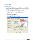
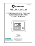
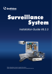
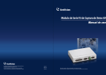
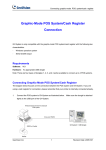
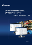
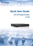
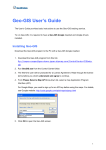
GV-Data Capture V3 Series User's Manual Before attempting to connect or operate this product, please read these instructions carefully and save this manual for future use. DCV31EV311-A-EN © 2013 GeoVision, Inc. All rights reserved. Under the copyright laws, this manual may not be copied, in whole or in part, without the written consent of GeoVision. Every effort has been made to ensure that the information in this manual is accurate. GeoVision is not responsible for printing or clerical errors. GeoVision, Inc. 9F, No. 246, Sec. 1, Neihu Rd., Neihu District, Taipei, Taiwan Tel: +886-2-8797-8377 Fax: +886-2-8797-8335 http://www.geovision.com.tw Trademarks used in this manual: GeoVision, the GeoVision logo and GV series products are trademarks of GeoVision, Inc. Windows and Windows XP are registered trademarks of Microsoft Corporation. May 2013 Preface Welcome to the GV-Data Capture V3 Series User’s Manual. The GV-Data Capture V3 Series includes GV-Data Capture V3, GV-Data Capture V3E and GV-Data Capture V3.1E. This Manual is designed for the following models and firmware versions: Model Firmware Version GV-Data Capture V3 V1.0 GV-Data Capture V3E (Ethernet Model) V3E V1.0 V3.1E V3.11 The GV-Data Capture is designed for the text-mode POS system and cash register. For how to connect the graphic-mode POS system, please visit our website: http://www.geovision.com.tw/english/faq/POSflowchart/graphic/posflow-3.htm i Contents Preface........................................................................................i Naming and Definition ............................................................iv 1. Getting Started ....................................................................1 1.1 Introduction .................................................................................................... 1 1.2 Unpacking....................................................................................................... 2 1.3 System Requirements.................................................................................... 2 2. Overview...............................................................................3 2.1 DIP Switch Setup............................................................................................ 4 2.2 Baud Rate Setup............................................................................................. 5 3. V3 Settings ...........................................................................6 3.1 Connections.................................................................................................... 6 3.1.1 DB9 Serial Interface ............................................................................................. 6 3.1.2 DB25 Serial Interface ........................................................................................... 7 3.1.3 Parallel Interface ................................................................................................. 8 3.1.4 Extending Distance.............................................................................................. 9 3.2 Configuring GV-System ............................................................................... 10 4. V3E Settings.......................................................................12 4.1 Configuring V3E ........................................................................................... 12 4.1.1 Fixed IP ...............................................................................................................13 4.1.2 DHCP..................................................................................................................15 4.1.2.1 Connection over LAN ................................................................................................... 15 4.1.2.2 Connection over Internet .............................................................................................. 18 4.2 Configuring GV-System ............................................................................... 22 4.2.1 Fixed IP ...............................................................................................................22 4.2.2 DHCP..................................................................................................................24 4.2.2.1 Connection over LAN ................................................................................................... 24 4.2.2.2 Connection over Internet .............................................................................................. 25 4.3 Setup and Password .................................................................................... 26 4.3.1 System Setup ......................................................................................................26 4.3.2 Updating Firmware ..............................................................................................27 4.3.3 Changing Password ............................................................................................28 ii 5. Specifications ....................................................................29 6. Troubleshooting ................................................................30 iii Naming and Definition POS System The GV-Data Capture V3 Series can work with both POS (Point of Sale) systems and cash registers. In this manual, we use POS systems to cover the two types of applications. GV-System GeoVision Analog and Digital Video Recording Software. The GVSystem also refers to Multicam System, GV-DVR System, GV-NVR System and GV-Hybrid DVR System at the same time. iv 1 Getting Started 1. Getting Started This section describes the features of the GV-Data Capture V3 Series, the inventory of the items that have supplied with GV-Data Capture, and the software version required for this application. 1.1 Introduction The GV-Data Capture V3 Series can interface with POS systems and GV-System to overlay transaction data on video footage. This allows you to investigate a transaction data by either live view or playback. The V3 Series comes in two models: V3 and V3E. The difference between the two models is the V3E features an Ethernet port, connecting POS systems to GV-System through LAN or Internet. The features of the V3 Series include: • V3E of Ethernet model provides LAN / Internet connection. • Supports both serial and parallel POS systems and cash registers. • Connects up to 16 POS systems to a single GV-System. For details on V3 Settings, see Chapter 3, and for details on V3E Settings, see Chapter 4. GV-Data Capture V3 GV-Data Capture V3 Series POS System (Cash Register) 1 GV-System GV-Data Capture V3 GV-Data Capture V3 Series POS System (Cash Register) 16 Figure 1 1 1.2 Unpacking • GV-Data Capture V3 / V3E box x 1 • DB9 RS-232 cable (1.8 meters) x 1 • DB9 RS-232 cable (3 meters) x 1 • DB25 RS-232 cable (1.8 meters) x 1 • Power Adaptor DC 5V x 1 • DB25 Male Printer Terminator x 1 • Wall Hook x 2 1.3 System Requirements • • 2 GV-Data Capture V3: GV-System version 6.0.2.0 or later GV-Data Capture V3E / V3.1E: GV-System version 8.0.4.0 or later 2 Overview 2. Overview This section identifies the various components of GV-Data Capture V3 Series. Front Panel Parallel Port to Printer /RS-232 (DB25) Female RS-232 (DB9) Male P RS-485 W + R RS-232 to DVR Rear Panel DC IN 5V RS-232 (DB9) Female SW1 SW2 SW3 1 2 Parallel Port from POS /RS-232 (DB25) Male 3 V3 Side Panel SW4 Baud Rate 2 0 345 1 Default 67 V3E Side Panel 2 Ethernet 0 345 1 SW4 Baud Rate 67 Default Figure 2 3 2.1 DIP Switch Setup To adjust the DIP Switches, refer to the chart below. • If your POS system is parallel type, set DIP Switch SW1 to Down; otherwise keep the default setting. • If the output interface of your POS system is DB25, set DIP Switch SW2 to Up; otherwise keep the default setting. • If the cable connecting your POS system to the GV-Data Capture is crossover, set DIP Switch SW3 to Down; otherwise keep the default setting. SW1 Up: Serial (Default) Down: Parallel SW2 Up Down 2 2 Up Down Up: Non-crossover (Default) Down: Crossover 4 1 Up: DB25 Mode Down: DB9 Mode (Default) SW3 1 3 3 Up Down 2 Overview 2.2 Baud Rate Setup To have the POS data transferred to the GV-System via the GV-Data Capture, you need to set the exact baud rate in each connected device, including the GV-Data Capture and POS systems. On the side panel of the GV-Data Capture, there is a Baud Rate Switch. Each number (from 0 to 7) on the Switch represents a kind of baud rate. Set the baud rate to correspond to that of the POS system. Switch Number Baud Rate 0 115200 (default value) 1 57600 2 38400 3 19200 4 9600 5 4800 6 2400 7 1200 5 3. V3 Settings The GV-Data Capture V3 Series supports both serial and parallel types of POS systems. This section introduces how to connect the two types of POS systems to the GV-Data Capture, and how to configure the GV-System to receive the data from the POS system. 3.1 Connections Identify the interface on your POS system used to connect a receipt printer to the POS system. It should be one of the three interfaces: DB9 Serial, DB25 Serial and Parallel. Following illustrates the connections of the three interfaces. 3.1.1 DB9 Serial Interface The illustration below is an example of a POS system using a DB9-DB25 cable. DB9 Female / Male 1 RS-232 DB9 Male / Female POS System GV-System GeoVision GV-DATA CAPTURE V3 DB9 Female DB9 Female / Male DB25 Male / Female DB9 Male 2 3 RS-232 RS-232 Printer • • The RS-232 cables (1) and (2) are supplied with the GV-Data Capture. • The physical distance between the POS system and GV-System should be less than The RS-232 cable (3) is supplied with the POS system. 10 meters (32 ft). Figure 3 6 3 V3 Settings 3.1.2 DB25 Serial Interface The illustration below is an example of a POS system using an RJ45-DB25 cable. 1 RJ-45 DB25 Female / Male POS System GV-System GeoVision GV-DATA CAPTURE V3 DB9 Female DB25 Male / Female DB25 Female / Male DB9 Male 2 3 RS-232 RS-232 Printer • • • The RJ-45 cable (1) is supplied with the POS system. The RS-232 cables (2) and (3) are supplied with the GV-Data Capture. The physical distance between the POS system and the GV-System should be less than 10 meters (32 ft). Figure 4 7 3.1.3 Parallel Interface To connect a parallel POS system, two precautions should be taken: 1. Set DIP Switch SW1 on the rear panel of the GV-Data Capture to Down. See 2.1 DIP Switch Setup. 2. If no receipt printer is attached, make sure to connect the supplied Terminator to the GV-Data Capture (as illustrated below), or the GV-System will not be able to receive any transaction data. 1 DB25 Male Parallel DB25 Female POS System GV-System GeoVision GV-DATA CAPTURE V3 DB9 Female or DB25 Male DB25 Female Printer • • 2 3 RS-232 Parallel Terminator The Parallel cables (1) and (3) are supplied with the POS system. The RS-232 cable and Terminator are supplied with the GV-Data Capture. Figure 5 8 DB9 Male 3 V3 Settings 3.1.4 Extending Distance The previous three diagrams assume the physical distance between the POS system and GV-System is within 10 meters (32 ft). If the distance between the two devices is greater than 10 meters, it is required to use GV-NET series, GV-Hub or GV-COM in the connection. • Using GV-NET series in the connection RS-232 RS-232 GV-NET box GV-NET card or GV-NET I/O card GV-Data Capture POS System • RS-485 GV-System Using GV-Hub / GV-COM in the connection RS-232 POS System USB RS-485 GV-Data Capture GV-HUB GV-COM GV-System Figure 6 Note: The maximum distance of RS-485 is 600 meters (2000 ft). 9 3.2 Configuring GV-System Configure the GV-System to receive the transaction data from the POS system. 1. Click the Configure button on the main screen, point to POS Application Setting, and then select POS Device Setup. The POS Server Setup dialog box appears. 2. Click the New tab. This dialog box appears. Figure 7 Printer Type: Select Serial or Parallel from the drop-down list. Device: Select a number to specify how many POS device are connected, and rename the POS device if necessary. Mapping Camera: Specify a channel to display POS data of the selected device. POS Module: Select the printer connected to the POS system. If it’s not Epson, select General for other brands. The parameter button: Click this button to configure the following parameters or keep default settings. Baud Rate: Select the baud rate corresponding to that of the POS system. 10 3 V3 Settings Data Bits: Select the number of data bits corresponding to that of the printer. Parity: Select None for the Serial POS system. Stop Bits: Select the stop bit corresponding to that of the printer. Cash Drawer Open Signal: This option is only available when an input module is configured in the GV-System. Assign the input module connected to the cash drawer. Every time when the cash drawer is open, it will be recorded in System Log for later retrieval. Use Codepage Mapping: This option is to support special character and symbol display. For details, see “Codepage Mapping”, Chapter 3, GV-DVR User’s Manual on the Surveillance System Software CD. Trace Mode: Check this option only after getting the recommendation from our technical support staff. 3. After above settings, click Add to add the POS system to the GV-System. 11 4. V3E Settings The GV-Data Capture V3E is the Ethernet version of the GV-Data Capture V3. The V3E allows you to connect POS systems to the GV-System through LAN or Internet, overcoming the distance limit of RS-232 or RS-485 cables. This section introduces how to set up the V3E on the network, how to configure the GVSystem to receive the transaction data from the POS system, and how to configure the system settings of the V3E. 4.1 Configuring V3E The GV-Data Capture V3E is able to support two network environments: • • Fixed IP DHCP Depending on your POS system’s network, choose Fixed IP for static IP addresses, or DHCP for dynamic IP addresses such as those assigned by an ISP or other DHCP server. 12 4 V3E Settings 4.1.1 Fixed IP If your POS system supports a static IP address, the wiring is illustrated as below: POS System (Cash Register) LAN or INTERNET GV-Data Capture V3.1E GV-Data Capture V3E GV-System Printer Figure 8 Note: For connections among the POS system, printer and GV-Data Capture V3E, see 3.1 Connections. After wiring work is complete, configure the V3E to match your network requirements. 1. Open an Internet browser, and type the web address: http://192.168.0.100 . This dialog box appears. Figure 9 13 2. In the User Name and Password fields, type default value admin and 1234 respectively, and then click OK. This page appears. Figure 10 Note: User Name is fixed, but Password is changeable. See 4.3.3 Changing Password. 3. In the GV-Data Capture V3E Name field, name the connected V3E. 4. Click Disable. Type the static IP address information, including IP Address, Subnet Mask, Default Gateway and Domain Name Server. 5. Click Submit. When the connection is established, the Status field indicates: Register Success. Note: If you like to use the domain name instead of IP address, you may use Domain Name Service as well. For details on domain name service, refer to 4.1.2 DHCP. 14 4 V3E Settings 4.1.2 DHCP If your POS system is using a dynamic IP address from a DHCP server, two types of DDNS servers are provided to tie a dynamic IP address to a static domain name or device name. This allows the GV-System to access your POS system by name. • For LAN connection, GV LocalDDNS Server is provided. • For Internet connection, two DDNS servers are supported: GeoVision DDNS Server and Dynamic Network Services Inc. (DynDNS). 4.1.2.1 Connection over LAN The GV-developed “LocalDDNS Server” can map a device name to your POS system’s varying IP address, by which the GV-System can access your POS system by the device name. The Local DDNS Server can be installed in either GV-System or a separate computer. The wiring of the LocalDDNS application is illustrated as below. POS System (Cash Register) LAN (Local DDNS Server) GV-Data Capture V3E GV-Data Capture V3E GV-System Printer Note: The Local DDNS Server can be installed in (1) GV-System or (2) a separate computer. Figure 11 Note: For connections among the POS system, printer and GV-Data Capture V3E, see 3.1 Connections. 15 Installing LocalDDNS Server To install the LocalDDNS Server in a computer: 1. Insert the Surveillance System Software CD to your computer. It will run automatically and pop up a window. 2. Select Install GeoVision System. 3. Select GeoVision LocalDDNS Server, and then follow on-screen instructions. 4. Run LocalDDNS.exe. The program will be minimized to the system tray. Figure 12 Configuring V3E for the Connection over LAN After running the LocalDDNS Server, configure the V3E to match your network requirements. 1. Open an Internet browser, and type the web address: http://192.168.0.100. The login dialog box (see Figure 9) appears. 2. In the User Name and Password fields, type default value admin and 1234 respectively, and click OK. The GV-Data Capture V3E Web interface (see Figure 10) appears. Note: User Name is fixed, but Password is changeable. See 4.3.3 Changing Password. 16 4 V3E Settings 3. Click Enable, and select Send to Local DDNS. 4. In Server IP field, type the IP address of the LocalDDNS server. 5. In Device Name field, keep the default setting or change it to match that of the GVSystem (see Figure 20). Figure 13 Note: The default value of the device name is pos. If more than one POS system is connected to the GV-System, assign each device a different name. 6. Click Submit to send the information to the LocalDDNS Server. When the connection is established, the Status field indicates: Register Success. 17 4.1.2.2 Connection over Internet DDNS (Dynamic Domain Name System) provides another way of accessing the POS system when using a dynamic IP. DDNS assigns a domain name to you POS system, so the GV-System can always access the POS system by the domain name. To enable the DDNS function, you should first apply for a domain name from the DDNS service provider’s website. There are 2 providers listed in the GV-Data Capture V3E: GeoVision DDNS Server and DynDNS.org. To register at the GeoVision DDNS Server, see the following section. For details on DynDNS, please consult them at www.dyndns.org. POS System (Cash Register) Internet (DDNS Server) GV-Data Capture V3E GV-Data Capture V3E GV-System Printer Note: Two DDNS servers are supported: (1) GV Dynamic DNS Server and (2) DynDNS. Figure 14 18 4 V3E Settings Registering a DDNS Domain Name To obtain a domain name from the GeoVision DDNS Server: 1. In the left menu pane, click System Setting, and then click the GeoVision DDNS button (see Figure 10). Or open an Internet browser, and type the web address http://ns.dipmap.com/register.aspx. This page appears. Figure 15 2. In the Username field, type a name. Username can be up to 16 characters with the choices of “a ~ z”, “0 ~9”, and “-”. Note that space or “-” cannot be used as the first character. 3. In the Password filed, type a password. Passwords are case-sensitive and must be at least 6 characters. Type the password again in the Re-type Password field for confirmation. 4. In the Word Verification section, type the characters or numbers shown in the box. In the example, type i8UCY in the required field. Word Verification is not case-sensitive. 19 5. Click the Send button. When the registration is complete, this page appears. Figure 16 For details, see “Using Dynamic DNS”, Chapter 13, GV-DVR User’s Manual on the Surveillance System Software CD. Note: The registered name will be invalid when it is not used for one month. 20 4 V3E Settings Configuring V3E for the Connection over Internet After registering a domain name on the DDNS Server, configure the V3E to meet your network requirements. 1. Follow the Steps 1 to 2 in 4.1.1 Fixed IP above. The GV-Data Capture V3E Web interface (see Figure 10) appears. 2. Click Enable, and select Send to DDNS. 3. Type the information of Host Name, User Name and Password that are registered on the DDNS Server. Figure 17 4. Click Submit to send the information. When the connection is established, the Status field indicates: Register Success. 21 4.2 Configuring GV-System After configuring the GV-Data Capture V3E, you need to set the GV-System to match your POS system’s network as well. 4.2.1 Fixed IP To set the GV-System for a static IP address network: 1. Click the Configure button on the main screen, point to POS Application Setting, and then select POS Device Setup. The POS Server Setup dialog box appears. 2. Click the New tab. This dialog box appears. Figure 18 Printer Type: Select TCP/IP Port from the drop-down list. Device: Use the drop-down list to select a number to specify how many POS device are connected, and rename the POS device in the next column if necessary. 22 Mapping Camera: Specify a channel to display POS data of the selected device. 4 V3E Settings POS Module: Select the printer connected to the POS system. If it’s not Epson, select General for other brands. Cash Drawer Open Signal: This option is only available when an input module is configured in the GV-System. Assign the input module connected to the cash drawer. Every time when the cash drawer is open, it will be recorded in System Log for later retrieval. Use Codepage Mapping: This option is to support special character and symbol display. For details, see “Codepage Mapping”, Chapter 3, GV-DVR User’s Manual on the Surveillance System Software CD. Trace Mode: Check this option only after getting the recommendation from our technical support staff. 3. Click the Data Capture IP Address Setting tab. This dialog box appears. Figure 19 4. Select Fixed IP, and type the IP address of the POS system. 5. In the Device Port field, keep default value 4000. Or modify it to match that of the POS system (see Figure 22). 6. In the Password field, type default value 1234. 7. If you need to change or view the configurations of V3E, click the Browse Device Setting button. The GV-Data Capture V3E Web interface (see Figure 10) will appear. 8. Click OK to add the POS system to GV-System. 23 4.2.2 DHCP To set the GV-System for a dynamic IP address network, first decide your connection network is LAN or Internet. 4.2.2.1 Connection over LAN 1. Follow Steps 1 to 3 described in 4.2.1 Fixed IP. The Data Capture Box IP Setting dialog box appears. Figure 20 2. Select IP Info. in (GV-Data Capture) Local DDNS Server. • If the LocalDDNS Server is installed in the GV-System, select In Host and type default value pos. Or modify it to match that of the POS system. • If the LocalDDNS Server is installed in a separate computer, select In another PC, and type its IP address. 3. In the Device Port field, keep default value 4000. Or modify it to match that of the POS system (see Figure 22). 4. In the Password field, type default value 1234. 5. If you need to change or view the configurations of V3E, click the Browse Device 24 4 V3E Settings Setting button. The GV-Data Capture V3E Web interface (see Figure 10) will appear. 6. Click OK to add the POS system to GV-System. 4.2.2.2 Connection over Internet 1. Follow the Steps 1 to 3 in 4.2.1 Fixed IP. The Data Capture Box IP Setting dialog box appears. Figure 21 2. Select IP Info. in DDNS Server, and type the domain name registered on the DDNS Server. 3. In the Device Port field, keep default value 4000. Or modify it to match that of the POS system (see Figure 22). 4. In the Password field, type default value 1234. 5. If you need to change or view the configurations of the V3E, click Browse Device Setting. The GV-Data Capture V3E Web interface (see Figure 10) will appear. 6. Click OK to add the POS system to GV-System. 25 4.3 Setup and Password You can execute certain system operations, change login password and view the version information of the firmware. 4.3.1 System Setup In the left menu pane, click Other Setting. This page appears. Figure 22 Web Server Port: Keeps the default value 80. Or makes changes if necessary. Baud Rate: Displays the baud rate set in the GV-Data Capture V3E. Data Bits: Select 7 bits or 8 bits for data transmission. Note this option is only available for GV-Data Capture V3.1E. Device Port: Keeps the default value 4000. Or modify it to match that of GV-System. See Figure 19. Mac Address: Indicates the MAC address of the network medium. Reboot System: Performs a warm boot of the GV-Data Capture V3E. This operation will keep the current configuration. Default Value: Resets all configuration parameters to their factory settings. This may take 5 seconds to complete. 26 4 V3E Settings 4.3.2 Updating Firmware To update the firmware of the GV-Data Capture V3E: 1. In the left menu pane, click Firmware Update. This page appears. Figure 23 2. Click the Browse… button to open the firmware file (*.bin) 3. Click the Upload button. This update procedure may take 60 seconds to complete. 4. When the Update is complete, a dialog box appears and asks you to reboot the system. Figure 24 5. Click OK, and the V3E starts the Reboot operation. Note: It is required to reboot the V3E after updating the firmware. Without rebooting, the firmware update is not complete. 27 4.3.3 Changing Password To change the login password: 1. In the left menu pane, click Password Setting. 2. On the Password Change page, type a password of 4 characters with the choices of “a ~ z” and “0 ~ 9”. Note that the password setting is case sensitive. Figure 25 28 5 Specifications 5. Specifications Specifications DB9 Female RS-232 from POS DB25 Male / Parallel Port RS-232 from POS / Parallel Port from POS DB9 Male RS-232 to Printer DB25 Female / Parallel Port RS-232 to Printer / Parallel Port to Printer DB9 Female RS-232 to DVR RJ-45 RJ-45 to DVR RS-485+ Connect to GV-NET / GV-Hub/GV-Com RS-485+ RS-485- Connect to GV-NET / GV-Hub/GV-Com RS-485- RS-232 from POS 1,200 bps~115,200 bps RJ-45 to DVR 10 / 100 Mbps RS-232 to DVR 1,200 bps~115,200 bps RS-485 to GV-Net / GV-Net Card / GV-Net/IO Card 1,200 bps~19,200 bps RS-485 to GV-Hub / GV-Com 600 bps~115,200 bps Input Output Communication DC IN Environmental Conditions Dimensions (W x H x D) Power Adapter DC5V, 2A Inner Positive Operating Temperature 0°C ~ 50°C (32°F ~ 122°F) Humidity 5%~95% (non-condensing) 161 x 34 x 123 mm (6.33” x 1.33” x 4.84”) Note: Specifications are subject to change without notice. 29 6. Troubleshooting Forgotten password or V3E’s IP address. Press the Reset button for 5 seconds. All the previous settings will be reset to defaults. Unable to configure when connecting more than one GV-Data Capture V3E to the same PC during first-time setup. 1. Complete the configuration of one V3E (see 4.1 Configuring V3E ). 2. After the settings are complete, go to Windows Start, point to Programs, select Accessories, and then click Command Prompt. This window appears. Figure 26 3. In the command line, type arp -d to clear ARP cache. This should help you avoid the IP address conflict in the next setup of V3E. 4. Return to the GV-Data Capture V3E Web interface (see Figure 10) to configure another V3E. 5. Repeat Steps 2 to 4 to complete all setups. No POS data is transferred to GV-System after the setup is complete. 1. At the GV-System, make sure the IP address, device port and password information are correctly typed (see 4.2 Configuring GV-System). 30 6 Troubleshooting 2. Check if the baud rates of the GV-Data Capture, POS system and GV-System are the same. For the baud rate setting in the GV-Data Capture, see 2.2 Baud Rate Setup. For the baud rate setting in the GV-System, see 3.2 Configuring GV-System. 3. If the network environments of the GV-Data Capture and GV-System have implemented NAT or Firewall, open the port 80 for the web connection and port 4000 for data transmission. Find out the dynamic IP address of your POS system. There are two ways to find out the dynamic IP address of your POS system: 1. Click the Browse Device Setting button (see Figure 20) to see the IP address on the IE browser. 2. Go to Windows Start, click Run, type the file name “enpos.ini” in the field, and press OK. The “enpos.ini” file appears as shown below, and you will see the IP address of the POS system. Figure 27 For more questions, please visit our website: http://www.geovision.com.tw/english/faq/POSflowchart/posflow-1_new.htm 31