1
2 - PROGRAMMING
TH-TD series
MICROPROCESSOR BASED
TEMPERATURE CONTROLLER
INSTRUCTION MANUAL
Rev. 03
1 - INSTRUMENT DESCRIPTION
2.1 - FAST PROGRAMMING OF THE SET POINT
This procedure permits rapid programming of the active Set Point
and possibly the alarm thresholds (see par 2.3)
Push key “P”, then release it and the display will visualise “SP n”
(where n is the number of the Set Point active at that moment) and
the programmed value.
To modify the value, press “UP” key to increase it or the “DOWN”
key to decrease it.
These keys change the value one digit at a time but if they are
pressed for more than one second, the value increases or decreases
rapidly and, after two seconds in the same condition, the changing
speed increases in order to allow the desired value to be reached
rapidly.
Once the desired value has been reached, by pushing key P it is
possible to exit by the fast programming mode or it is possible to
visualise the alarm thresholds (see par. 2.3).
To exit the fast Set programming it is necessary to push key P, after
the visualisation of the last Set Point, or alternatively, if no key is
pressed for approx. 15 seconds, the display will return to normal
functioning automatically.
2.2 - SELECTION OF THE CONTROL STATE AND PARAMETER
PROGRAMMING
By pushing key "P" and holding it down for approx. 2 sec. it is
possible to enter into the main selection menu.
Using the "UP" or DOWN” keys, it is then possible to roll over the
selections:
THT Series
"OPEr"
"ConF"
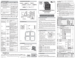
1 - Key P : This is used to access the programming parameters and
to confirm selection.
2 - Key DOWN : This is used to decrease the values to be set and
to select the parameters. If the key is held down, the user returns to
the previous programming level until he exits the programming mode.
Outside the programming mode it permits visualisation of the current
measured by the TAHB input.
3 - Key UP : This is used to increase the values to be set and to
select the parameters. If the key is held down, the user returns to the
previous programming level until he exits the programming mode.
Outside the programming mode it permits visualisation of the output
control power.
4 - Key T : This is a key with a function programmable by par.
“USrb”. It can be set to : Activate Autotuning and Selftuning
functions, swap the instrument to manual control, silence the alarm,
change the active Set Point, deactivate control.
5 - Led OUT1 : indicates the state of output OUT1
6 - Led OUT2 : indicates the state of output OUT2
7 - Led SET : when flashing, it indicates access to the programming
mode.
8 - Display PV : It normally indicates the process value
9 - Display SV : It normally indicates the active Set value, however
it can be programmed, on par. “diSP”, to visualize other values.
to enter into the operating parameters menu
to enter into the configuration parameters menu
To enter the menu “OPEr”, select the option “OPEr” and press the
key “P”.
The display will now show the code identifying the first group of
parameters (“ ]SP “) and by pressing the “UP” and “DOWN” keys it
will be possible to select the group of parameters to be modified.
Once the desired group of parameters has been selected, the code
identifying the first parameter of the selected group will be visualised
by pushing the “P” key.
Again using the “UP” and “DOWN” keys, it is possible to select the
desired parameter and, if the key “P” is pressed, the display will
show the parameter’s code and its programming value, which can be
modified by using the “UP” or “DOWN” keys.
Once the desired value has been programmed, push key “P” once
more: the new value will be memorised and the display will show
only the code of the selected parameter.
By using the “UP” or “DOWN” keys, it is then possible to select a
new parameter (if present) and modify it as described above.
To select another group of parameters, keep the “UP” or “DOWN”
key pressed for approx. 2 sec., afterwards the display will return to
visualise the code of the group of parameters.
Release the key and by using the “UP” and “DOWN” keys, it will be
possible to select a new group (if present).
To exit the programming mode, no key should be pressed for approx.
20 seconds, or keep the “UP” or “DOWN” pressed until exit from the
programming mode is obtained.
To enter the menu "ConF" a PASSWORD is required.
At this request, enter, using keys “UP” and “DOWN”, the number
381 and push key “P”.
If an incorrect password is entered, the instrument returns to the
previous control state.
If the password is correct, the display will visualise the code
identifying the first group of parameters (“ ]SP “) and with keys “UP”
and “DOWN” it will be possible to select the desired group of
parameters
Phone: 800.894.0412 - Fax: 208.368.0415 - Web: www.ctiautomation.net - e.mail: [email protected]
The programming and exit modes for the “ConF” menu are the same It is also recommended that all the electrical circuits connected to the
instrument must be protect properly, using devices (ex. fuses)
as those described for menu “OPEr”.
proportionate to the circulating currents.
It is strongly recommended that cables with proper insulation,
according to the working voltages and temperatures, be used.
Furthermore, the input cable of the probe has to be kept separate
from line voltage wiring. If the input cable of the probe is screened, it
has to be connected to the ground with only one side.
We recommend that a check should be made that the parameters
are those desired and that the application functions correctly before
connecting the outputs to the actuators so as to avoid malfunctioning
that may cause irregularities in the plant that could cause damage to
people, things or animals.
3 - INFORMATION ON INSTALLATION AND USE
3.1 – PERMITTED USE
The instrument has been projected and manufactured as a
measuring and control device to be used according to EN61010-1 for
the altitudes operation until 2000 ms.
The use of the instrument for applications not expressly permitted by
the above mentioned rule must adopt all the necessary protective
measures.
The instrument CAN’T be used in dangerous environments
(flammable or explosive) without adequate protection.
The installer must ensure that EMC rules are respected, also after
the instrument installation, if necessary using proper filters.
Whenever a failure or a malfunction of the device may cause
dangerous situations for persons, thing or animals, please remember
that the plant has to be equipped with additional devices which will
guarantee safety.
DATASENSOR S.p.A. and its legal representatives do not
assume any responsibility for any damage to people, things or
animals deriving from violation, wrong or improper use or in
any case not in compliance with the instrument’s features.
3.2 – MECHANICAL MOUNTING
The instrument, in DIN case 48 x 48 mm, is designed for flush-in
panel mounting.
Make a hole 45 x 45 mm and insert the instrument, fixing it with the
provided special bracket.
We recommend that the gasket is mounted in order to obtain the
front protection degree as declared. Avoid placing the instrument in
environments with very high humidity levels or dirt that may create
condensation or introduction of conductive substances into the
instrument.
Ensure adequate ventilation to the instrument and avoid installation
in containers that house devices which may overheat or which may
cause the instrument to function at a higher temperature than the
one permitted and declared.
Connect the instrument as far away as possible from sources of
electromagnetic disturbances such as motors, power relays, relays,
solenoid valves, etc.
The instrument can be removed from its housing from the front side :
it is recommended that the instrument be disconnected from the
power supply when it is necessary to carry out this operation.
3.3 - ELECTRICAL CONNECTION
Carry out the electrical wiring by connecting only one wire to each
terminal, according to the following diagram, checking that the power
supply is the same as that indicated on the instrument and that the
load current absorption is no higher than the maximum electricity
current permitted.
As the instrument is built-in equipment with permanent connection
inside housing, it is not equipped with either switches or internal
devices to protect against overload of current: the installation will
include a two-phase circuit-breaker, placed as near as possible to
the instrument, and located in a position that can easily be reached
by the user and marked as instrument disconnecting device which
interrupts the power supply to the equipment.
3.4 - ELECTRICAL WIRING DIAGRAM
4 – FUNCTIONS
4.1 - MEASURING AND VISUALIZATION
All the parameters referring measurements are contained in the
group “]InP”.
We recommend to switch on and off the instrument when these
parameters are modified, in order to obtain a correct measuring.
For the instruments with input for temperature probes (tc, rtd) it’s
possible to select, through par. “Unit”, the unit of measurement (°C,
°F) and, through par. “dP” (Pt100, PTC and NTC only) the desired
resolution (0=1°; 1=0,1°).
The instrument allows for measuring calibration, which may be used
to recalibrate the instrument according to application needs, by using
par. “OFSt” and “rot”.
Programming par. “rot”=1,000, in par. “OFSt” it is possible to set a
positive or negative offset that is simply added to the value read by
the probe before visualisation, which remains constant for all the
measurements.
If instead, it is desired that the offset set should not be constant for
all the measurements, it is possible to operate the calibration on any
two points.
In this case, in order to decide which values to program on par.
“OFSt” and “rot”, the following formulae must be applied :
“rot” = (D2-D1) / (M2-M1)
“OFSt” = D2 - (“rot” x M2)
where:
M1 =measured value 1
D1 = visualisation value when the instrument measures M1
M2 =measured value 2
D2 = visualisation value when the instrument measures M2
It then follows that the instrument will visualise :
DV = MV x “rot” + “OFSt”
where: DV = visualised value
MV= measured value
By using par. “FiL” it is possible to program time constant of the
software filter for the input value measured, in order to reduce noise
sensitivity (increasing the time of reading).
In case of measurement error, the instrument supplies the power as
programmed on par. “OPE”.
This power will be calculated according to cycle time programmed for
the PID controller, while for the ON/OFF controllers the cycle time is
automatically considered to be equal to 20 sec.
DATASENSOR SpA - TH-TD series - INSTRUCTION MANUAL - Rev. 02 - PAGE 2
Phone: 800.894.0412 - Fax: 208.368.0415 - Web: www.ctiautomation.net - e.mail: [email protected]
By using par. “InE” it is also possible to decide the conditions of the
input error, allowing the instrument to give the power programmed
on par. “OPE” as output.
The possibilities of par. “InE” are :
= Or : the condition occurs in case of over-range or probe breakage
= Ur : the condition occurs in case of under-range or probe breakage
= Our : the condition occurs in case of over-range or under-range or
probe breakage
Using par. “diSP”, located in the group “]PAn”, it is possible to set
normal visualization of the display SV which can be the active Set
Point (SP.F), the Set Point operating when there are active ramps
(SP.o), the alarm threshold AL1(AL1) or can be switched OFF (OFF).
4.2 - OUTPUTS CONFIGURATION
The instrument’s outputs can be programmed by entering the group
of parameters “]Out, where the relative parameters “O1F” , “O2F”
are located.
The outputs can be set for the following functions :
- Main control output (1.rEG)
- Secondary control output (2.rEG)
- Alarm output normally open (ALno)
- Alarm output normally closed (ALnc)
- Alarm output normally closed with led reverse indication (ALni)
- Output deactivated (OFF)
The coupling outputs number outputs – number alarms can be made
in the group referring to the alarm to the alarm (“ ]AL1”).
4.3 – ON/OFF CONTROL (1rEG)
All the parameters referring to the ON/OFF control are contained in
the group “]rEG”.
This type of control can be obtained by programming par."Cont" =
On.FS or = On.FA and works on the output programmed as 1.rEG,
depending on the measure, on the active Set Point “SP”, on the
functioning mode "Func” and on the hysteresis "HSEt".
The instrument carries out an ON/OFF control with symmetric
hysteresis if “Cont" = On.FS or with asymmetrical hysteresis if “Cont”
= On.Fa.
The control works in the following way : in the case of reverse
action, or heating (“FunC”=HEAt), it deactivates the output, when the
process value reaches [SP + HSEt] in case of symmetrical
hysteresis, or [SP] in case of asymmetrical hysteresis and is then
activated again when the process value goes below value [SP HSEt].
Vice versa, in case of direct action or cooling ("Func”=CooL), it
deactivates the output, when the process value reaches [SP - HSEt]
in case of symmetrical hysteresis, or [SP] in case of asymmetrical
hysteresis and is activated again when the process value goes
above value [SP + HSEt].
4.4 - NEUTRAL ZONE ON/OFF CONTROL (1rEG - 2rEG)
All the parameters referring to Neutral Zone ON/OFF control are
contained in the group “]rEG”.
This type of control can be obtained when 2 outputs are
programmed respectively as 1rEG and 2rEG and the par. “Cont” =
nr .
The Neutral Zone control is used to control plants in which there is
an element which causes a positive increase (ex. Heater, humidifier,
etc.) and an element which causes a negative increase (ex. Cooler,
de-humidifier, etc).
The control functions works on the programmed outputs depending
on the measurement, on the active Set Point “SP” and on the
hysteresis "HSEt".
The control works in the following way : it deactivates the outputs
when the process value reaches the Set Point and it activates the
output 1rEG when the process value goes below value [SP - HSEt],
or it activates the output 2rEG when the process value goes above
[SP + HSEt].
Consequently, the element causing a positive increase has to be
connected to the output programmed as 1rEG while the element
causing a negative increase has to be connected to the output
programmed as 2rEG.
If 2rEG output is used to control compressor is possible to use the
“Compressor Protection” function that has the meaning to avoid
compressor “short cycles”.
This function allows a control by time on the output 2rEG activation,
independently by the temperature control request.
The protection is a “delayed after deactivation” type.
This protection permits to avoid the output activation for a time
programmable on par. “CPdt” (expressed in sec.); the output
activation will occurs only after the elapsing of time “CPdt”.
The time programmed on parameter “CPdt” is counted starting from
the last output deactivation.
Obviously, whether during the time delay caused by the compressor
protection function, the regulator request should stop, the output
activation foreseen after time “CPdt” would be erased.
The function is not active programming “CPdt” =OFF.
The led relative to 2rEG output blinks during the phases of output
activation delay, caused by “Compressor Protection” function.
4.5 - SINGLE ACTION PID CONTROL (1rEG)
All the parameters referring to PID control are contained in the group
“]rEG”.
The Single Action PID control can be obtained by programming
par."Cont" = Pid and works on the output 1rEG depending on the
active Set Point “SP”, on the functioning mode "Func” and on the
instrument’s PID algorithm with two degree of freedom.
In order to obtain good stability of the process variable, in the event
of fast processes, the cycle time “tcr1” has to have a low value with
a very frequent intervention of the control output.
In this case use of a solid state relay (SSR) is recommended for
driving the actuator.
DATASENSOR SpA - TH-TD series - INSTRUCTION MANUAL - Rev. 02 - PAGE 3
Phone: 800.894.0412 - Fax: 208.368.0415 - Web: www.ctiautomation.net - e.mail: [email protected]
The Single Action PID control algorithm foresees the setting of the
following parameters :
"Pb" – Proportional Band
"tcr1" – Cycle time of the output 1rEG
"Int" – Integral Time
"rS" – Manual Reset (if “Int =0 only)
"dEr" – Derivative Time
“FuOC” - Fuzzy Overshoot Control
This last parameter allows the variable overshoots at the start up of
the process or at the changing of the Set Point to be avoided.
Please remember that a low value on this parameter reduces the
overshoot while a high value increase it.
1: Value “FuOC” OK
2: Value “FuOC” too high
3: Value “FuOC” too low
4.6 - DOUBLE ACTION PID CONTROL (1rEG - 2rEG)
All the parameters referring to PID control are contained in the group
“]rEG”.
The Double Action PID control is used to control plants where there
is an element which causes a positive increase (ex. Heating) and an
element which causes a negative increase (ex. Cooling).
This type of control can be obtained when 2 outputs are
programmed respectively as 1rEG and 2rEG and the par. “Cont” =
Pid.
The element causing a positive increase has to be connected to the
output programmed as 1rEG while the element causing a negative
increase has to be connected to the output programmed as 2rEG.
The Double Action PID control works on the outputs 1rEG and 2rEG
depending on the active Set Point “SP” and on the instrument’s PID
algorithm with two degrees of freedom.
In order to obtain good stability of the process variable, in case of
fast processes, the cycle times “tcr1” and “tcr2” have to have a low
value with a very frequent intervention of the control outputs.
In this case use of solid state relays (SSR) to drive the actuators is
recommended.
The Double Action PID control algorithm needs the programming of
the following parameters :
"Pb" – Proportional Band
"tcr1" – Cycle time of the output 1rEG
“tcr 2” – Cycle time of the output 2rEG
"Int" – Integral Time
"rS" – Manual Reset (if “Int =0 only)
"dEr" – Derivative Time
“FuOC” - Fuzzy Overshoot Control
"Prat" - Power Ratio or relation between power of the element
controlled by output 2rEG and power of the element controlled by
output 1rEG.
If par. “Prat” = 0, the output 2rEG is disabled and the control
behaves exactly as a single action PID controller, through output
1rEG.
this operation, the parameters are stored into the instrument’s
memory and remain constant during control.
The SELFTUNING function (rule based "TUNE-IN") instead allows
control monitoring and the continuous calculation of the parameters
during control.
Both functions automatically calculate the following parameters :
"Pb" – Proportional Band
"tcr1" – Cycle time of the output 1rEG
"Int" – Integral Time
"dEr" – Derivative Time
“FuOC” - Fuzzy Overshoot Control
and, for the Double Action PID control, also :
“tcr 2” – Cycle time of the output 2rEG
"Prat" - Ratio P 2rEG/ P 1rEG
To activate the AUTOTUNING function proceed as follows :
Press the T pushbutton, at this point the Auto-tuning function is
activated and is indicated by the flashing led AT/ST.
The regulator carries out several operations on the connected plant
in order to calculate the most suitable PID parameters.
If “Auto” = 1 or “Auto” = 2, and if, at the Auto-tuning start, the
condition for the lower process value is not found (with “Func”
=HEAt) than [SP- |SP/2|] or higher (with “Func” =CooL) than [SP+
|SP/2|], the display will show “ErAt” and the instrument will be
swapped to normal control conditions according to the previously
programmed parameters.
To make the error “ErAt” disappear, swap the instrument to the OFF
control (OFF) and then turn it to automatic control (rEG).
The Autotuning cycle duration has been limited to 12 hours
maximum.
If Autotuning is not completed within 12 hours, the instrument will
show "noAt" on the display.
In case of probe error, the instrument automatically stops the cycle in
progress.
The values calculated by Autotuning are automatically stored in the
instrument’s memory at the end of the correct PID parameters tuning.
Note : The instrument is already programmed in our factory to carry
out auto-tuning at every instrument switch on ("Auto" = 1).
To activate the SELFTUNING function proceed as follows
1) Program par. "SELF" = yES
2) Exit from the parameter programming.
3) Connect the instrument to the controlled plant.
4) Activate Selftuning selecting par. “tunE” in the main menu (or by
correctly programming key “T”).
When the Selftuning function is active, the led AT/ST is permanently
lit up and all the PID parameters ("Pb", "Int", "dEr", etc.) are no longer
visualized.
4.8 - REACHING OF THE SET POINT AT CONTROLLED SPEED
AND AUTOMATIC SWITCHING BETWEEN TWO SET POINTS
(RISE RAMP, FALL RAMP AND DWELL TIME)
All the parameters referring to the ramps functioning are contained in
the group “]rEG”.
It is possible to reach the set point in a predetermined time (in any
case longer than the time the plant would naturally need). This could
be useful in those processes (heating or chemical treatments, etc.)
where the set point has to be reached gradually, in a predetermined
time.
Once the instrument has reached the first Set Point (SP1) it is
possible to have automatic switching to the second Set Point (SP2)
after a set time, thus obtaining a simple automatic thermic cycle.
These functions are available for all the programmable controls (PID
single and double action, ON/OFF and Neutral Zone ON/OFF).
4.7 - AUTOTUNING AND SELFTUNING FUNCTIONS
All the parameters referring to the AUTOTUNING and SELFTUNING The function is determined by the following parameters :
"SLor" - Gradient of rise ramp (Process value < Set point)
functions are contained in the group “]rEG”.
The AUTOTUNING and SELFTUNING functions permit the expressed in unit/minute
"SLoF" - Gradient of fall ramp (Process value > Set point)
automatic tuning of the PID controller.
The AUTOTUNING function permits the calculation of the PID expressed in unit/minute.
parameters by means of a FAST type tuning cycle and, at the end of
DATASENSOR SpA - TH-TD series - INSTRUCTION MANUAL - Rev. 02 - PAGE 4
Phone: 800.894.0412 - Fax: 208.368.0415 - Web: www.ctiautomation.net - e.mail: [email protected]
The alarm is depending on the process value (AL1) and before to set
his functioning it’s necessary to establish to which output the alarm
has to correspond to.
First of all it’s necessary to configure, in the parameters group
“]Out”, the parameters relative to the outputs required as alarm
(“O1F” , “O2F”) programming the parameter relative to the desired
output as follows :
= ALno if the alarm output has to be ON when the alarm is active,
while it’s OFF when the alarm is not active
= ALnc if the alarm output has to be ON when the alarm is not
active, while it’s OFF when the alarm is active
= ALni if the alarm output has to be ON when the alarm is not active,
while it is OFF when the alarm is active but with reverse led
indication (led ON= alarm OFF).
Have now access at the group “]AL1”, and program on par. “OAL1”
, to which output the alarm signal has to be sent.
The alarm functioning is instead defined by parameters :
"AL1t " – ALARM TYPE
"Ab1" – ALARM CONFIGURATION
“AL1” – ALARM THRESHOLD
“AL1L” – LOW ALARM THRESHOLD (for band alarm) OR
MINIMUM SET OF AL1 ALARM THRESHOLD (for low or high alarm)
“AL1H” - HIGH ALARM THRESHOLD (for band alarm) OR
MAXIMUM SET OF AL1 ALARM THRESHOLD (for low or high
alarm)
“HAL1” - ALARM HYSTERESIS
Examples : start from values lower than SP and with decreasing of “AL1d” – ALARM ACTIVATION DELAY (in sec.)
SP.
"AL1i" – ALARM BEHAVIOUR IN THE EVENT OF
MEASUREMENT ERROR
4.9 - SOFT-START FUNCTION
All the parameters referring to the Soft -Start functioning are "AL1t" – ALARM TYPE
: the alarm output can behave in six
contained in the group “]rEG”.
different ways.
The Soft-Start function only works through PID control and allows LoAb = ABSOLUTE LOW ALARM: The alarm is activated when the
the limitation of control power when the instrument is switched on, for process value goes below the alarm threshold set on parameter
a programmable period of time.
"AL1”. With this mode is possible to program the minimum and the
This is useful when the actuator, driven by the instrument, may be maximum set of “AL1” by “AL1L” and “AL1H” parameters.
damaged excess power supplied when the application is not yet in
the normal rating. (ex. for certain heating elements).
The function depends on the following parameters :
“St.P” – Soft-Start power
“Sst” – Soft-Start time (expressed in hh.mm)
HiAb = ABSOLUTE HIGH ALARM: The alarm is activated when the
The possible function modes are the following :
1) If both parameters are programmed with values other than OFF, process value goes higher than the alarm threshold set on
when switched on the instrument gives an output power as parameter "AL1". With this mode is possible to program the minimum
programmed on par. “St.P” for the time programmed on par. “SSt”. and the maximum set of “AL1” by “AL1L” and “AL1H” parameters.
Practically, the instrument works in manual condition and switches to
automatic control at the elapsing of time “SSt”.
It is advisable not to program a power “St.P” that is too high as the
function is not deactivated when the automatic control power is
found to be lower than the programmed one.
LHAb = ABSOLUTE BAND ALARM: The alarm is activated when the
2) If par. “St.P” = OFF and a value is set on par. “SSt” , at the switch process value goes under the alarm threshold set on parameter
on, the power calculated by the PID controller is divided by the time "AL1L" or goes higher than the alarm threshold set on parameter
“SSt”, in order to calculate a ramp. The output power starts from 0 "AL1H".
and is progressively increased, depending on the calculated ramp,
until the “SSt” time is reached or until the power overcomes the
power calculated by the PID controller.
To disable the Soft-Start function simply program par. “Sst” = OFF
Whenever, a measurement errors occurs during the Soft-Start
LodE = DEVIATION LOW ALARM: The alarm is activated when the
execution, the function is interrupted and the instrument gives an
process value goes below the value [SP + AL1]. With this mode is
output power as programmed on par. “OPE”.
possible to program the minimum and the maximum set of “AL1” by
If the measurement is restored, the Soft-Start is still deactivated.
“AL1L” and “AL1H” parameters.
If it’s desired to activate the Autotuning with Soft-Start set par.
“Auto”=4.
The Autotuning will start automatically at the end of programmed
Soft-Start cycle at the condition that the process value is lower (with
“Func” =HEAt) than [SP- |SP/2|] or higher (with “Func” =CooL) than
HidE = DEVIATION HIGH ALARM: The alarm is activated when the
[SP+ |SP/2|].
process value goes above the value [SP + AL1]. With this mode is
possible to program the minimum and the maximum set of “AL1” by
4.10 – ALARM FUNCTIONING (AL1)
“AL1L” and “AL1H” parameters.
4.10.1 – ALARM OUTPUT CONFIGURATION
"dur.t" – Dwell time of Set Point SP1 before automatic switching to
Set Point 2 SP2 (expressed in hrs. and min.).
The functions are deactivated when the relative parameters are =
InF.
When the Set Point value is changed or at switch on, the instrument
automatically determines which of the two values “SLor” or “SLoF” it
has to use.
Note: In case of PID control, if Auto-tuning is desired whilst the ramp
function is active, this will not be carried out until the tuning cycle has
been completed.
It is therefore recommended that Auto-tuning be started avoiding
activating the ramp function and, once the tuning is finished,
deactivate Auto-tuning (“Auto” = OFF), program the desired ramps
and, if it automatic tuning is desired, enable the Self-tuning function.
DATASENSOR SpA - TH-TD series - INSTRUCTION MANUAL - Rev. 02 - PAGE 5
Phone: 800.894.0412 - Fax: 208.368.0415 - Web: www.ctiautomation.net - e.mail: [email protected]
"AL1i" - ALARM ACTIVATION IN CASE OF MEASUREMENT
ERROR: This allows one to establish how the alarm have behave in
the event of a measurement error (yES=alarm active; no=alarm
deactivated).
LHdE = DEVIATION BAND ALARM: The alarm is activated when the
process value goes below the value [SP + AL1L] or goes above than 4.10.2 - ALARMS HYSTERESIS
The alarm function depend s on alarm hysteresis (par. "HAL1"),
the value [SP + AL1H]
which works in asymmetric way.
In the event of low alarm, the alarm will be activated when the
process value goes below the alarm threshold value and will be
deactivated when it goes above the alarm threshold + "HAL1" ; in
case of high alarm, the alarm will be activated when the process
value goes above the alarm threshold value and will be deactivated
"Ab1" - ALARM CONFIGURATION: This parameter can assume a when it goes below the alarm threshold - "HAL1".
value between 0 and 15.
The number to be set, which will correspond to the function desired,
is obtained by adding the values reported in the following
descriptions :
ALARM BEHAVIOUR AT SWITCH ON: the alarm output may behave
in two different ways, depending on the value added to par. “Ab1”.
+0 = NORMAL BEHAVIOUR: The alarm is always activated when
there are alarm conditions.
+1 = ALARM NOT ACTIVATED AT SWITCH ON: If, when switched
on, the instrument is in alarm condition, the alarm is not activated. It
will be activated only when the process value is in non-alarm
conditions and then back in alarm conditions.
For the band alarms, the example of the low alarm is applicable to
the low threshold ("AL1L") while the example of the high alarm is
applicable to the high threshold ("AL1H").
ALARM DELAY: the alarm output may behave in two different ways
depending on the value added to par. “Ab1”.
+0 = ALARM NOT DELAYED: The alarm is immediately activated
when the alarm condition occurs.
+2 = ALARM DELAYED: When the alarm condition occurs, delay
counting begins, as programmed on par. “AL1d” (expressed in sec.)
and the alarm will be activated only after the elapsing of that time.
ALARM LATCH: : the alarm output may behave in two different ways
depending on the value added to par. “Ab1”.
+ 0 = ALARM NOT LATCHED: The alarm remains active in alarm
conditions only.
+ 4 = ALARM LATCHED: The alarm is active in alarm conditions and
remains active even when these conditions no longer exist, until the
correctly programmed key T, (“USrb”=Aac) has been pushed.
4.11 - LOOP BREAK ALARM FUNCTION
All the parameters referring to the Loop Break alarm function are
contained in the group “]LbA”.
The Loop Break alarm is available on all the instruments, which
intervenes when, for any reason (short-circuit of a thermocouple,
thermocouple inversion, load interruption), the loop control is
interrupted.
First of all, it is necessary to establish to which output the alarm has
to correspond.
To do this it is necessary to set the parameter relative to the output
to be used (“O1F” , “O2F”) in the group “]Out”, programming the
parameter as :
= ALno if the alarm output has to be ON when the alarm is active
while it is OFF when the alarm is not active.
= ALnc if the alarm output has to be ON when the alarm is not active
while it is OFF when the alarm is active.
= ALni if the alarm output has to be ON when the alarm is not active,
while it is OFF when the alarm is active but with reverse led
indication (led ON= alarm OFF).
Enter group “]LbA” and program which output the alarm signal has
to be addressed to on par. “OLbA”,.
The Loop Break alarm is activated if the output power remains at the
100% of the value for the time programmed on par. "LbAt"
(expressed in sec.).
To avoid false alarms, the value of this parameter has to be set
considering the time the plant takes to reach the Set point when the
measured value is a long distance from it (for example at the plant
start-up).
On alarm intervention, the instrument visualizes the message “LbA”
and behaves as in the case of a measurement error giving a power
output as programmed on par. “OPE” (programmable in the group
“]InP”).
To restore normal functioning after the alarm, select the control
mode “OFF” and then re-program the automatic control (“rEG”) after
checking the correct functioning of probe and actuator.
To exclude the Loop Break alarm, set “OLbA” = OFF.
ALARM AKNOWLEDGEMENT: : the alarm output may behave in
two different ways depending on the value added to par. “Ab1”.
+ 0 = ALARM NOT AKNOWLEDGED: The alarm always remains
active in alarm conditions.
+ 8 = ALARM AKNOWLEDGED: The alarm is active in alarm 4.12 - FUNCTIONING OF KEY “T”
conditions and can be deactivated by key “T” if properly The function] of key “T” can be set through par. “USrb” contained in
the group ““ PAn”.
programmed (“USrb”=ASi), and also if alarm conditions still exist.
The parameter can be programmed as :
Phone: 800.894.0412 - Fax: 208.368.0415 - Web: www.ctiautomation.net - e.mail: [email protected]
= noF : no function
20 O2F Functioning of output 2 1.rEG / 2.rEG ALno CONF
= tunE : Pushing the key for 1 sec. at least, it is possible to
ALno / ALnc
activate/deactivate Autotuning or Selftuning
ALni / OFF
= OPLO : Pushing the key for 1 sec. at least, it is possible to swap
from automatic control (rEG) to manual one (OPLO) and vice versa. Group “AL1” (parameters relative to alarm AL1)
= Aac : Pushing the key for 1 sec. at least, it is possible to
Par.
Description
Range
Def.
Note
acknowledge the alarm. (see par. 4.10.1)
21 OAL1 Output where alarm AL1 Out1 / Out2 / Out2 CONF
= ASi : Pushing the key for 1 sec. at least, it is possible to
is addressed
OFF
acknowledge an active alarm (see par. 4.10.1)
22 AL1t Alarm AL1 type
LoAb / HiAb
HiAb OPER
= CHSP : Pushing the key for 1 sec. at least, it is possible to select
LHAb / LodE
one of the 4 pre-programmed Set Points on rotation.
HidE / LHdE
= OFF : Pushing the key for 1 sec. at least, it is possible to swap
23
Ab1
Alarm
AL1
functioning
0 ÷ 15
0
CONF
from automatic control (rEG) to OFF control (OFF) and vice versa.
24 AL1 Alarm AL1 threshold
AL1L÷ AL1H
0
OPER
25 AL1L Low threshold band -1999 ÷ AL1H -1999 CONF
alarm AL1 or Minimum
set alarm AL1 for high
or low alarm
5 - PROGRAMMABLE PARAMETERS
26 AL1H High threshold band AL1L ÷ 9999 9999 CONF
alarm AL1 or Maximum
5.1 - PARAMETERS TABLE
set alarm AL1 for high
or low alarm
Here following are described all the parameters available on the
OFF ÷ 9999
1
CONF
instrument. Some of them could be not present or because they are 27 HAL1 Alarm AL1 hysteresis
OFF ÷ 9999
OFF CONF
depending on the type of instrument or because they are 28 AL1d Activation delay of
alarm AL1
sec.
automatically disabled as unnecessary.
29
AL1i
Alarm
AL1
activation
in
no
/ yES
no
CONF
The default (Def.) parameter is the factory configuration.
case of measuring error
The Note indicates the menu (ConF or OPEr) of the parameter.
Group “SP” (parameters relative to the Set Point)
Par.
Description
Range
Def.
1 nSP programmable Set point
1÷4
1
2 SPAt Active Set point
1 ÷ nSP
1
3 SP1 Set Point 1
SPLL ÷ SPHL
0
4 SP2 Set Point 2
SPLL ÷ SPHL
0
5 SP3 Set Point 3
SPLL ÷ SPHL
0
6 SP4 Set Point 4
SPLL ÷ SPHL
0
7 SPLL Low Set Point
-1999 ÷ SPHL -50
8 SPHL High Set Point
SPLL ÷ 9999 1500
Group “InP” (parameters relative to the measure input)
Par.
Description
Range
Def.
J
9 SEnS Probe type
J / CrAL / S /
Ir.J / Ir.CA /
Pt1 / 0.50 /
0.60 / 12.60
10 SSC Low scale limit in case
-1999 ÷ FSC
0
of input with V/I signals
11 FSC High scale limit in case
SSC ÷ 9999
0
of input with V/I signals
12 dP Number of decimal
Pt1 / Ptc / ntc:
0
figures
0/1
13 Unit Temperature unit of
°C / °F
°C
measurement
14 FiL Input digital filter
0FF÷ 20.0
0.5
sec.
15 OFSt Measuring Offset
-1999 ÷ 9999
0
16 rot Rotation
of
the 0.000 ÷ 2.000 1.000
measuring straight line
17 InE “OPE” functioning in Our / Or / Ur
OUr
case of measuring error
18 OPE Output power in case of -100 ÷ 100
0
measuring error
%
Note
CONF
CONF
CONF
CONF
CONF
CONF
CONF
CONF
Note
OPER
CONF
CONF
OPER
CONF
CONF
CONF
CONF
CONF
CONF
Group “Out” (parameters relative to the outputs)
Par.
Description
Range
Def.
Note
19 O1F Functioning of output 1 1.rEG / 2.rEG 1.rEG CONF
ALno / ALnc
ALni / OFF
Group “LbA” (parameters relative to Loop Break Alarm)
Par.
Description
Range
Def.
30 OLbA Output where alarm LbA Out1 / Out2 / OFF
is addressed
OFF
31 LbAt Time necessary to
OFF ÷ 9999
OFF
activate alarm LbA
sec.
Group “rEG” (parameters relative to the control)
Par.
Description
Range
32 Cont Control type
Pid / On.FA
On.FS / nr
33 Func Functioning mode
HEAt / CooL
output 1rEg
34 HSEt Hysteresis of ON/OFF
0 ÷ 9999
control
35 CPdt Compressor Protection OFF÷ 9999
time for 2.rEG
sec.
36 Auto Autotuning Fast enable
OFF /
1/2/3/4
37 SELF Selftuning enable
no / yES
38 Pb Proportional band
0 ÷ 9999
39 Int Integral time
OFF ÷ 9999
40 dEr Derivative time
OFF ÷ 9999
41 FuOc Fuzzy overshoot control 0.00 ÷ 2.00
42 tcr1 Cycle time of output 1
0.1 ÷ 130.0
43 Prat Power ratio 2rEg / 1rEg 0.01 ÷ 99.99
44 tcr2 Cycle time of 2rEg
0.1 ÷ 130.0
45 rS Manual reset
-100.0÷100.0
%
46 SLor Gradient of rise ramp
0.00 ÷ 99.99
/ InF
unit/min.
47 dur.t Duration time
0.00 ÷ 99.59
/ InF
hrs.-min.
48 SLoF Gradient of fall ramp
0.00 ÷ 99.99
/ InF
unit / min.
49 St.P Soft-Start power
OFF /
-100 ÷ 100 %
Def.
Pid
Note
CONF
CONF
Note
OPER
HEAt CONF
1
OPER
0
CONF
3
CONF
no
50
200
50
0,5
20,0
1.00
10.0
0.0
CONF
OPER
OPER
OPER
OPER
OPER
CONF
CONF
CONF
InF
CONF
InF
CONF
InF
CONF
OFF
CONF
DATASENSOR SpA - TH-TD series - INSTRUCTION MANUAL - Rev. 02 - PAGE 7
Phone: 800.894.0412 - Fax: 208.368.0415 - Web: www.ctiautomation.net - e.mail: [email protected]
50
SSt
Soft-Start time
OFF /
0.1÷7.59
/ InF
hrs.-min.
OFF
Group “PAn” (parameters relative to the user interface)
Par.
Description
Range
Def.
tunE
51 USrb Functioning of key “T”
noF / tunE /
OPLO / Aac /
ASi / CHSP /
OFF
dEF
52 diSP Variable visualized on
dEF / Pou /
the display
SP.F / SP.o /
AL1
53 AdE Shift value for the shift
OFF...9999
2
index functioning
54 Edit Fast programming of
SE / AE / SAE SAE
active Set Point and
/ SAnE
alarms
CONF
Note
CONF
CONF
CONF
CONF
5.2 - PARAMETERS DESCRIPTION
GROUP “ ]SP” (PARAMETERS RELATIVE TO THE SET POINT):
These allow the setting of the control Sets and the Sets
function modes.
nSP – NUMBER OF PROGRAMMABLE SET POINTS: This allows
definition of the number of Set Points which will be programmed and
stored (from 1 to 4).
SPAt – ACTIVE SET POINT : If more than one Set Point is stored,
this allows selection of the active Set Point.
SP1 - SET POINT 1: Value of the Set Point n. 1
SP2 - SET POINT 2: Value of the Set Point n. 2 (it appears if “nSP”
>2 only)
SP3 - SET POINT 3: Value of the Set Point n. 3 (it appears if “nSP”
>3 only)
SP4 - SET POINT 4: Value of the Set Point n. 4 (it appears if “nSP”
=4 only)
SPLL – LOW SET POINT: Lower value programmable as Set Point
SPHL – HIGH SET POINT : Higher value programmable as Set
Point.
]
GROUP “ InP” (PARAMETERS RELATIVE TO THE INPUTS):
These permit the definition of visualization modes of the
variable measured by the probe.
SEnS – PROBE TYPE: Depending on model, it permits to select the
type of probe :
- thermocouples: J (J), K (CrAL), S (S) or infrared sensors IRS serie
with J (Ir.J) or K (Ir.CA) linearization.
- thermoresistances: Pt100 IEC (Pt1)
- thermistors PTC KTY81-121 (Ptc) or NTC 103AT-2 (ntc)
SSC – LOW SCALE LIMIT IN EVENT OF INPUT WITH V/I SIGNALS
: This is the value the instrument has to visualise when the minimum
value that can be measured on the scale is present at the input.
FSC – HIGH SCALE LIMIT IN EVENT OF INPUT WITH V/I SIGNALS
: This is the value the instrument has to visualise when the maximum
value that can be measured on the scale is present at the input.
dP – NUMBER OF DECIMAL FIGURES: It permits to decide if the
measuring resolution has to be 1 (0), 0.1 (1), 0.01 (2), 0.001 (3). In
case of Pt100, PTC and NTC temperature probes the allowed
resolutions are 1° (0) and 0.1° (1).
Unit – TEMPERTURE UNIT OF MEASUREMENT : When the
temperature is measured by temperature probes, this parameter
permits definition if the visualisation is expressed as degree
Centigrade (°C) or Fahrenheit (°F).
Filt – INPUT DIGITAL FILTER : This permits programming of the
constant of time of the software filter referring to the measured input
value (in sec.) in order to reduce noise sensitivity (increasing the
time of reading).
OFSt – MEASURING OFFSET: Positive or negative Offset which is
added to the value measured by the probe.
rot – ROTATION OF THE MEASURING STRAIGHT LINE: In this
way the offset programmed on par. “OFSt” is not constant for all
measurements. By programming “rot”=1.000, the value “OFSt” is
simply added to the value read by the probe before visualisation and
it remains constant for all the measurements. If instead one does not
want the programmed offset to be constant for all the measurements,
it is possible to carry out calibration on two desired values.
In this case, to define the values to be programmed on par. “OFSt”
and “rot”, it is necessary to enforce the following formulae :
“rot” = (D2-D1) / (M2-M1)
“OFSt” = D2 - (“rot” x M2)
where: M1 =measured value 1; D1 = visualisation value when the
instrument measures M1
M2 =measured value. 2; D2 = visualisation value when the
instrument measures M2
It then follows that the instrument will visualise : DV = MV x “rot” +
“OFSt”
where: DV = visualised value; MV= measured value
InE – “OPE” FUNCTIONING IN CASE OF MEASUREMENT
ERROR: This defines the error conditions of the input allowing the
instrument to give the power programmed on par. “OPE” as output.
The possibilities are :
= Or : the condition occurs in case of over-range or probe breakage
= Ur : the condition occurs in case of under-range or probe breakage
= Our : the condition occurs in case of over-range or under-range or
probe breakage
OPE – OUTPUT POWER IN CASE OF MEASUREMENT ERROR:
This permits setting of the power that the instrument has to give as
output in case of measurement error. For the ON/OFF regulators the
power is calculated considering a cycle time equal to 20 sec.
GROUP “ ] Out” (PARAMETERS RELATIVE TO THE OUTPUTS):
They permit to program the outputs functioning.
O1F – FUNCTIONING OF OUTPUT OUT 1: This defines the
functioning of output OUT 1 as: control output 1 (1.rEG), control
output 2 (2.rEG), alarm output as normally open (ALno), output alarm
normally closed (ALnc), output alarm normally closed with led
reverse indication (ALni), output not used (OFF).
O2F - FUNCTIONING OF OUTPUT OUT 2: Similar to “O1F” but
referring to output OUT2.
GROUP “ ]AL1” (PARAMETERS RELATIVE TO ALARM AL1):
These permit setting of the process alarm AL1 function.
OAL1 – OUTPUT WHERE ALARM AL1 IS ADDRESSED: It defines
to which output the alarm AL1 has to be addressed.
AL1t – ALARM AL1 TYPE: permits the choice of behaviour for alarm
A1, by 6 different selections:
= LoAb – ABSOLUTE LOW ALARM : The alarm is activated when
the process value goes below the alarm threshold set on parameter
"AL1".
= HiAb - ABSOLUTE HIGH ALARM: The alarm is activated when the
process value goes above the alarm threshold set on parameter
"AL1".
= LHAb - ABSOLUTE BAND ALARM: The alarm is activated when
the process value goes below the alarm threshold set on parameter
"AL1L" or goes higher than alarm set on parameter "AL1H".
= LodE – DEVIATION LOW ALARM: The alarm is activated when the
process value goes below the value [SP + AL1]
= HidE – DEVIATION HIGH ALARM: The alarm is activated when the
process value goes above the value [SP + AL1]
= LHdE – DEVIATION BAND ALARM: The alarm is activated when
the process value goes below the value [SP + AL1L] or goes above
the value [SP + AL1H]
Ab1 – ALARM AL1 FUNCTION: This permits definition of alarm AL1
functions, by entering a number between 0 and 15. The number to
be programmed, that corresponds to the desired function, is obtained
adding the values reported in the following description :
ALARM BEHAVIOUR AT SWITCH ON:
DATASENSOR SpA - TH-TD series - INSTRUCTION MANUAL - Rev. 02 - PAGE 8
Phone: 800.894.0412 - Fax: 208.368.0415 - Web: www.ctiautomation.net - e.mail: [email protected]
+0 = NORMAL BEHAVIOUR: The alarm is always activated when
there are alarm conditions.
+1 = ALARM NOT ACTIVATED AT SWITCH ON: If, at switch on, the
instrument is in alarm condition, the alarm is not activated. It will be
activated only when the process value goes beyond and then returns
to alarm conditions.
ALARM DELAY:
+0 = ALARM NOT DELAYED: The alarm is immediately activated
when the alarm condition occurs.
+2 = ALARM DELAYED: When the alarm condition occurs, delay
counting starts as programmed on par. “ALnd” (expressed in sec.)
and the alarm will be activated only after this time has elapsed.
ALARM LATCH: :
+ 0 = ALARM NOT LATCHED: The alarm remains active in alarm
conditions only.
+ 4 = ALARM LATCHED: The alarm is active in alarm conditions and
remains active even if these conditions no longer exist, until the
correctly programmed key T (“USrb”=Aac) has been pushed
ALARM AKNOWLEDGEMENT: :
+ 0 = ALARM NOT AKNOWLEDGED: The alarm remains always
active in alarm conditions.
+ 8 = ALARM AKNOWLEDGED: The alarm is active in alarm
conditions and can be deactivated through key “T” if properly
programmed (“USrb”=ASi), also if alarm conditions still exist.
AL1 – ALARM AL1 THRESHOLD : Alarm AL1 threshold for low and
high alarms.
AL1L – LOW ALARM AL1 : Alarm AL1 low threshold when the alarm
is a band type or minimum set of AL1 alarm threshold when the alarm
is low or high type.
AL1H – HIGH ALARM AL1: Alarm AL1 high threshold when the alarm
is a band type or maximum set of AL1 alarm threshold when the
alarm is low or high type.
HAL1 - ALARM AL1 HYSTERESIS: Asymmetrical semi-band relative
to alarm AL1 threshold which defines the deactivation value of alarm
AL1.
AL1d – ACTIVATION DELAY OF ALARM AL1: This permits
definition of alarm delay activation AL1 when the delay function on
par. “Ab1” is activated.
AL1i – ALARM AL1 ACTIVATION IN CASE OF MEASUREMENT
ERROR: This permits a definition of measurement error conditions,
i.e whether the alarm has to be active ("yES") or not ("no").
GROUP “LbA” (PARAMETERS RELATIVE TO THE LOOP
BREAK ALARM): this contains the parameters relative to the
Loop Break alarm (control loop interruption), which intervenes
when, for any reason (short-circuit of a thermocouple, load
interruption, etc) the control loop is interrupted.
OLbA – OUTPUT WHERE THE LOOP BREAK ALARM IS
ADDRESSED: This defines to which output the LOOP BREAK alarm
has to be addressed.
LbAt – TIME NECESSARY TO ACTIVATE THE LOOP BREAK
ALARM : Delay time to the intervention of the Loop Break alarm.
The alarm intervenes when the output power remains at 100% for
the time programmed on this parameter (in sec.)
GROUP “ ]rEG” (PARAMETERS RELATIVE TO THE CONTROL):
this contains the parameters relative to control functions.
Cont – CONTROL TYPE: This permits selection of one of the
possible control modes offered by the instrument : PID (Pid),
ON/OFF with asymmetrical hysteresis (On.FA), ON/OFF with
symmetrical hysteresis (On.FS), Neutral Zone ON/OFF (nr).
Func – FUNCTIONING MODE OUTPUT 1rEG: this permits one to
decide whether the control output 1rEG has to carry out a reverse
action, as for example a Heating process ("HEAt") or a direct action,
as for example a Cooling process ("CooL").
HSEt –ON/OFF CONTROL HYSTERESIS: Semi-band relative to the
Set Point which defines the activation and deactivation values of the
control output/s in case of ON/OFF control (On.FA, On.FS, nr).
CPdt – COMPRESSOR PROTECTION DELAY TIME: The delay
time is counted starting from the last 2rEG output switch off , when
it’s used as Neutral zone control mode, during which the output is
kept in off state. The output will be switched on when the
temperature regulator requires it at this time is elapsed. The function
in deactivated programming "CPdt" = OFF.
Auto – AUTOTUNING FAST ENABLE : this parameter allows one
to decide how autotuning has to be carried out. The possible
selections are :
= 1 – if autotuning is desired automatically, each time the instrument
is switched on, on the condition that the process value is lower (with
“Func” =HEAt) than [SP- |SP/2|] or higher (with “Func” =CooL) than
[SP+ |SP/2|].
= 2 – if autotuning is desired automatically, the next time the
instrument is switched on, on the condition that the process value is
lower (with “Func” =HEAt) than [SP- |SP/2|] or higher (with “Func”
=CooL) than [SP+ |SP/2|], and once the tuning is finished, the par.
“Auto” is automatically swapped to the OFF state
= 3 - if manual autotuning is desired, by selecting par. “tunE” in the
main menu or by correctly programming key “T” as “USrb” = tunE. In
this case the autotuning starts without any control on the process
value condition. It is recommended to use this option, starting the
auto-tuning when the process value is as far as possible from the
Set Point because, in order to feature the autotuning FAST with its
best performances , it is preferable to respect this condition.
= 4 - if it’s desired to activate the autotuning automatically at the end
of programmed Soft-Start cycle. The Autotuning will start at the
condition that the process value is lower (with “Func” =HEAt) than
[SP- |SP/2|] or higher (with “Func” =CooL) than [SP+ |SP/2|].
= OFF - Autotuning disabled.
When it’s occurring an Autotuning cycle, led AT blinks.
SELF – SELFTUNING ENABLE: Parameter used to enable (yES) or
disable (no) the Self-tuning function. Once the function has been
enabled, the Self-tuning has to be started by selecting item “tunE”, in
the main menu, or through key T properly programmed (“USrb” =
tunE).When the Self-tuning function is active, led AT is permanently
lit, and all the PID parameters ("Pb", "Int", "dEr", ecc.) are no longer
visualised.
Pb – PROPORTIONAL BAND: Width of the band around the Set
Point within which the proportional control is performed.
Int – INTEGRAL TIME: Integral time to be programmed in the PID
algorithm, expressed in sec.
dEr – DERIVATIVE TIME: : Derivative time to be programmed in the
PID algorithm, expressed in sec.
FuOc - FUZZY OVERSHOOT CONTROL: Parameter that permits
the elimination of the variable over-shoots at the start up of the
process or at the changing of the Set Point. A low value of this
parameter reduces the overshoot while a high value increase it.
tcr1 – CYCLE TIME OF OUTPUT 1rEG : Cycle time of output 1rEG
with PID control mode, expressed in sec..
Prat – POWER RATIO 2rEG / 1rEG : Parameter where it is possible
to program the power ratio between the element controlled by output
2rEG (ex.Cooling) and the element controlled by output 1rEG (ex.
Heating) in case of PID double action control.
tcr2 - CYCLE TIME OF OUTPUT 2rEG : Cycle time of output 2rEG
with PID double action control mode, expressed in sec..
rS - MANUAL RESET: Power Offset added to the power increase of
the proportional term, in order to eliminate the error when it is not
present the integral value. This parameter is only visualised when
“Int” =0.
Parameters relative to the ramps, allowing the Set Point to be
reached in a predetermined time.
Furthermore, once the first Set (SP1) has been reached, it is
possible to have automatic switching to the second Set (SP2)
after a programmable time, thus obtaining a simple thermal
cycle (functions available for all the control types)
SLor – GRADIENT OF RISE RAMP: Gradient of rise ramp to be
carried out when the process value is lower than the active Set
Point, expressed in unit/minute.
Programming the parameter = InF the ramp is not active.
dur.t - DWELL TIME: Dwell time of the Set Point SP1 before the
automatic switching to SP2 (expressed in hrs. and min.)
DATASENSOR SpA - TH-TD series - INSTRUCTION MANUAL - Rev. 02 - PAGE 9
Phone: 800.894.0412 - Fax: 208.368.0415 - Web: www.ctiautomation.net - e.mail: [email protected]
Using this parameter, once the first Set (SP1) has been reached, it is
possible to have automatic switching to the second Set (SP2) after a
programmable time, thus obtaining a simple thermal cycle.
Programming the parameter = InF the function is not active.
SLoF - GRADIENT OF FALL RAMP: Gradient of fall ramp to be
carried out when the process value is higher than the active Set
Point, expressed in unit/minute.
Programming the parameter = InF the ramp is not active.
Parameters relative to the Soft-Start function, which allows
limitation of control power, when the instrument is switched
on, for a predetermined time. This function is only available for
PID control.
St.P - SOFT START POWER: If parameter “SSt” is programmed
with a value other than OFF, this is the power given as output at the
instrument switch on, for the time “SSt”.
Practically speaking, the instrument works in manual condition and
switches to automatic control at the elapsing of time “SSt”.
If instead par. “St.P” = OFF and a value is set on par. “SSt” at
switch on, the power calculated by the PID controller is divided by
the time “SSt”, in order to calculate a ramp. The output power starts
from 0 and is progressively increased, according to the calculated
ramp, until the time “SSt” is reached or until the power overcomes
the power calculated by the PID controller.
SSt - SOFT START TIME (for PID control only): Duration time in
hours and min. of the Soft-Start described on pa. “St.P”.
To disable the Soft-Start function set par. “SSt” = OFF.
GROUP “ ]PAn” (PARAMETERS RELATIVE TO THE USER
INTERFACE) : This contains the parameters relative to the key
T and display functions.
Usrb – KEY T FUNCTION : Decides which function is associated to
key T. The possible selections are :
= noF : no function
= tunE : Pushing the key for 1 sec. at least, it is possible to
activate/deactivate the Autotuning or the Self-tuning
= OPLO : Pushing the key for 1 sec. at least, it is possible to swap
from the automatic control (rEG) to the manual one (OPLO) and vice
versa.
= Aac : Pushing the key for 1 sec. at least, it is possible to
acknowledge the alarm.
= ASi : Pushing the key for 1 sec. at least, it is possible to
acknowledge an active alarm
= CHSP : Pushing the key for 1 sec. at least, it is possible to select
one of the 4 pre-programmed Set Points on rotation.
= OFF : Pushing the key for 1 sec. at least, it is possible to swap
from the automatic control (rEG) to the OFF control (OFF) and vice
versa.
diSP - VARIABLE VISUALISED ON THE DISPLAY SV: Parameter
trough which it’s possible to decide what is visualised on the display
SV : the active Set Point (= SP.F), the Set Point active when there
are ramps (= SP.o), the control power (= Pou), the alarm threshold
AL1 (= AL1) or it can be switched off (OFF).
Edit - FAST PROGRAMMING OF ACTIVE SET POINT AND
ALARMS: This decides which are the Sets that can be programmed
by the fast procedure. The parameter can be programmed as :
=SE: The active Set Point can be modified while the alarm
thresholds cannot be modified
=AE :The active Set Point cannot be modified while the alarm
thresholds can be modified
=SAE: If the active Set Point or the alarm thresholds can be modified
=SAnE: If the active Set Point or the alarm thresholds cannot be
modified
6 - PROBLEMS, MAINTENANCE AND GUARANTEE
6.1 - ERROR SIGNALLING
Error
Reason
---Probe interrupted
Verify
Action
the
correct
uuuu
oooo
ErAt
The measured variable
is under the probe’s
limits (underrange)
The measured variable
is over
the probe’s
limits (overrange)
Auto-tuning not possible
because the process
value is higher (with
“Func” =HEAt) than
[SP- |SP/2|] or lower
(with “Func” =CooL)
than [SP+ |SP/2|]
noAt
Autotuning not finished
within 12 hours
LbA
Loop control interrupted
(Loop break alarm)
ErEP
Possible anomaly of the
EEPROM memory
connection between probe
and instrument and then
verify
the
correct
Swap the instrument into
OFF control (OFF) and
successively
into
automatic control (rEG) in
order to make disappear
the error message.
Once the error has been
found, try to repeat the
autotuning.
Check the functioning of
probe and actuator and
try to repeat the
autotuning.
Check the functioning of
probe and actuator and
swap the instrument into
(rEG) control
Push key “P”
In error conditions the instrument provides an output power as
programmed on par “OPE” and activates the desired alarm, if the
relative parameters “AL1i” have been programmed = yES.
6.2 – CLEANING
We recommend to clean the instrument with a cloth slightly wet of
water or not abrasive cleaners or containing solvents which may
damage the instrument.
6.3 – GUARANTEE AND REPAIRS
The instrument is under warranty against construction vices or
defected material, if noticed within the terms in force at the
purchasing date.
The guarantee is limited to the repairs or to the substitution of the
instrument.
The eventual opening of the housing, the violation of the instrument
or the wrong use and installation of the product means the automatic
decay of the guarantee.
In case of defective instrument, noticed within or out of the guarantee
period, do contact our sales department to obtain the shipment
authorisation.
The defective product must be shipped to DATASENSOR with the
detailed description of the failures found and without any fees or
charge for DATASENSOR, safe different agreements.
7 - TECHNICAL DATA
7.1 – ELECTRICAL DATA
Power supply: 24 VAC/VDC, 100... 240 VAC +/- 10%
Frequency AC: 50/60 Hz
Power consumption: 5 VA approx.
Input/s: 1 input for temperature probes: tc J,K,S ; infrared sensors
IRS J e K; RTD Pt100 IEC; PTC KTY 81-121 (990 Ω @ 25 °C);
NTC 103AT-2 (10KΩ @ 25 °C) or mV signals 0...50 mV, 0...60 mV,
12 ...60 mV
Output/s: Up to 2 outputs. Relay SPST-NO (8 A-AC1, 3 A-AC3 / 250
VAC) ; or in tension to drive SSR (8mA/ 8VDC).
Auxiliary supply output: 10 VDC / 20 mA Max.
Electrical life for relay outputs: 100000 operations
Installation category: II
Measurement category: I
Protection class against electric shock: Class II for Front panel
DATASENSOR SpA - TH-TD series - INSTRUCTION MANUAL - Rev. 02 - PAGE 10
Phone: 800.894.0412 - Fax: 208.368.0415 - Web: www.ctiautomation.net - e.mail: [email protected]
Insulation: Reinforced insulation between the low voltage section
(supply and relay outputs) and the front panel; Reinforced insulation
between the low voltage section (supply and relay outputs) and the
extra low voltage section (inputs, SSR outputs); No insulation
between input and SSR outputs.
7.2 – MECHANICAL DATA
Housing: Self-extinguishing plastic, UL 94 V0
Dimensions: 48 x 48 mm DIN, depth 98 mm
Weight: 225 g approx.
Mounting: Flush in panel in 45 x 45 mm hole
Connections: 2 x 1 mm2 screw terminals block
Degree of front panel protection : IP 54 mounted in panel with gasket
Pollution situation: 2
Operating temperature: 0 ... 50 °C
Operating humidity: 30 ... 95 RH% without condensation
Storage temperature: -10 ... +60 °C
7.3 – FUNCTIONAL FEATURES
Control: ON/OFF, single and double action PID
Measurement range: according to the used probe (see range table)
Display resolution: according to the probe used 1/0,1/0,01/0,001
Overall accuracy: +/- 0,5 % fs
Max. cold junction compensation drift (in tc) : 0,1 °C/°C with
operating temperature 0 ... 50 °C after warm-up of 20 min.
Sampling rate: 130 ms.
Display: 4 digit dual display, 1 Red (PV) and 1 green (SV), h 7 mm
Compliance: ECC directive EMC 89/336 (EN 61326), ECC directive
LV 73/23 and 93/68 (EN 61010-1)
7.4
- MEASURING RANGE TABLE
INPUT
tc J
“SEnS” = J
tc K
“SEnS” = CrAl
tc S
“SEnS” = S
Pt100 (IEC)
“SEnS” = Pt1
PTC (KTY81-121)
“SEnS” = Ptc
NTC (103-AT2)
“SEnS” = ntc
“dP” = 0
0 ... 1000 °C
32 ... 1832 °F
0 ... 1370 °C
32 ... 2498 °F
0 ... 1760 °C
32 ... 3200 °F
-200 ... 850 °C
-328 ... 1562 °F
-55 ... 150 °C
-67 ... 302 °F
-50 ... 110 °C
-58 ... 230 °F
“dP”= 1, 2, 3
----------199.9 ... 850.0 °C
-199.9 ... 999.9 °F
-55.0 ... 150.0 °C
-67.0 ...302.0 °F
-50.0 ... 110.0 °C
-58.0 ... 230.0 °F
For any further information please contact:
DATASENSOR SpA
7.5 – MECHANICAL DIMENSIONS, PANEL CUT-OUT AND
MOUNTING [mm]
Via Lavino 265 - 40050 Monte San Pietro (BO) ITALY
www.datasensor.com
THT Series
DATASENSOR SpA - TH-TD series - INSTRUCTION MANUAL - Rev. 02 - PAGE 11
Phone: 800.894.0412 - Fax: 208.368.0415 - Web: www.ctiautomation.net - e.mail: [email protected]
INDEX
1
1.1
1.2
2
2.1
2.2
TH-TD
Advanced
MICROPROCESSER BASED
TEMPERATURE REGULATOR
INSTRUCTION MANUAL
Rel. 02 (ENG)
DATASENSOR S.p.A.
FOREWORD:
This manual contains the information necessary for the product to be
installed correctly and also instructions for its maintenance and use;
we therefore recommend that the utmost attention is paid to the
following instructions.
Though this manual has been issued with the greatest care,
DATASENSOR S.p.A. will not take any responsibility deriving from
its use.
The same applies to each person or Company involved in the
issuing of this manual.
This document is the exclusive property of DATASENSOR S.p.A.
which forbids any reproduction and divulgation , even in part, of the
document, unless expressly authorized.
DATASENSOR S.p.A. reserves the right to make any formal or
functional changes at any moment and without any notice.
INSTRUMENT DESCRIPTION
GENERAL DESCRIPTION
FRONT PANEL DESCRIPTION
PROGRAMMING
FAST PROGRAMMING OF THE SET POINT
SELECTION OF CONTROL STATE AND PARAMETERS
PROGRAMMING
2.3 PARAMETER PROGRAMMING LEVELS
2.4 CONTROL STATES
2.5 ACTIVE SET POINT SELECTION
3
INFORMATION ON INSTALLATION AND USE
3.1 PERMITTED USE
3.2 MECHANICAL MOUNTING
3.3 ELECTRICAL CONNECTIONS
3.4 ELECTRICAL WIRING DIAGRAM
4
FUNCTIONS
4.1 MEASURING AND VISUALIZATION
4.2 OUTPUT CONFIGURATION
4.3 ON/OFF CONTROL
4.4 NEUTRAL ZONE ON/OFF CONTROL
4.5 SINGLE ACTION PID CONTROL
4.6 DOUBLE ACTION PID CONTROL
4.7 PID CONTROL FOR MOTORIZED ACTUATORS WITH
TIME POSITIONING
4.8 AUTOTUNING AND SELFTUNINGFUNCTIONS
4.9 CONTROL POWER LIMITATION
4.10 LIMITATION OF THE CONTROL POWER VARIATION
SPEED (MAXIMUM RATE OF RISE)
4.11 SPLIT RANGE FUNCTION
4.12 REACHING OF SET POINT AT CONTROLLED SPEED
AND AUTOMATIC COMMUTATION BETWEEN TWO
SET POINTS
4.13 SOFT-START FUNCTION
4.14 ALARM FUNCTIONS
4.14.1 ALARM OUTPUT CONFIGURATION
4.14.2 ALARM HYSTERESIS
4.15 HEATER BREAK ALARM FUNCTION
4.16 LOOP BREAK ALARM FUNCTION
4.17 FUNCTION OF KEY T
4.18 DIGITAL INPUT
4.19 RS 485 SERIAL INTERFACE
4.20 PARAMETERS CONFIGURATION BY KEY01
5
PROGRAMMABLE PARAMETERS
5.1 PARAMETERS TABLE
5.2 PARAMETERS DESCRIPTION
6
PROBLEMS , MAINTENANCE AND GUARANTEE
6.1 ERROR WARNINGS
6.2 CLEANING
6.3 GUARANTEE AND REPAIRS
7
TECHNICAL DATA
7.1 ELECTRICAL DATA
7.2 MECHANICAL DATA
7.3 MECHANICAL DIMENSIONS, PANEL CUT-OUT AND
MOUNTING
7.4 FUNCTIONAL DATA
7.5 MEASURING RANGE TABLE
7.6 INSTRUMENT ORDERING CODES
1 - INSTRUMENT DESCRIPTION
1.1 – GENERAL DESCRIPTION
TH-TD is a “single loop” microprocessor-based regulator, with
ON/OFF, Neutral Zone ON/OFF, PID single action, PID dual action
(direct and reverse) control, PID for motorized actuators with time
positioning control.
The instrument is equipped with AUTOTUNING FAST function,
SELFTUNING function and automatic calculation of the FUZZY
OVERSHOOT CONTROL parameter for PID control.
The PID control has a particular algorithm with TWO DEGREES OF
FREEDOM that optimises the instrument’s features independently of
the event of process disturbances and Set Point variations.
DATASENSOR - TH-TD - INSTRUCTION MANUAL - Rel. 02 - PAGE 1
Phone: 800.894.0412 - Fax: 208.368.0415 - Web: www.ctiautomation.net - e.mail: [email protected]
Furthermore, the instrument allows for RS485 serial communication
using MODBUS-RTU communication protocol and a transmission
speed up to 38.400 baud.
The process value is visualized on 4 red displays, the Set value is
visualized on 4 green displays while the outputs status is indicated
by 4 leds.
The instrument provides for the storage of 4 Set Points and can
have up to 4 outputs : relay type or can drive solid state relays type
(SSR), or it is also possible to have up to 2 analogue outputs.
The input is programmable and accepts temperature probes
(Thermocouples J,K,S,B,C,E,L,N,R,T; Thermo-resistances PT100,
Thermistors PTC and NTC; Infrared sensors mod. IRS) and
normalized analogue signals (0/4..20 mA, 0/1..5 V, 0/2..10 V,
0..50/60 mV, 12..60 mV).
The instrument can be equipped with an input for the current
transformer, working as a Heater Break Alarm function and with a
programmable digital input as an alternative to output OUT4.
Other important available functions are: Loop-Break Alarm function,
control power limitation, limitation of the variation speed of the
control power, split-range, reaching of the Set Point at controlled
speed, ramp and dwell function, Soft-Start function, parameters
protection on different levels.
To modify the value, press “UP” key to increase it or the “DOWN”
key to decrease it.
These keys change the value one digit at a time but if they are
pressed for more than one second, the value increases or decreases
rapidly and, after two seconds in the same condition, the changing
speed increases in order to allow the desired value to be reached
rapidly.
Once the desired value has been reached, by pushing key P it is
possible to exit by the fast programming mode or it is possible to
visualise the alarm thresholds (see par. 2.3).
To exit the fast Set programming it is necessary to push key P, after
the visualisation of the last Set Point, or alternatively, if no key is
pressed for approx. 15 seconds, the display will return to normal
functioning automatically.
2.2 - SELECTION OF THE CONTROL STATE AND PARAMETERS
PROGRAMMING
By pushing key "P" and holding it down for approx. 2 sec. it is
possible to enter into the main selection menu.
1.2 - FRONT PANEL DESCRIPTION
THT Series
1 - Key P : This is used to access the programming parameters and
to confirm selection.
2 - Key DOWN : This is used to decrease the values to be set and to
select the parameters. If the key is held down, the user returns to the
previous programming level until he exits the programming mode.
Outside the programming mode it permits visualisation of the current
measured by the TAHB input, on the SV display.
3 - Key UP : This is used to increase the values to be set and to
select the parameters. If the key is held down, the user returns to the
previous programming level until he exits the programming mode.
Outside the programming mode it permits visualisation of the output
control power, on the SV display.
4 - Key T : This is a key with a function programmable by par.
“USrb”. It can be set to : Activate Autotuning and Selftuningfunctions,
swap the instrument to manual control, silence the alarm, change the
active Set Point, deactivate control.
5 - Led OUT1 : indicates the state of output OUT1
6 - Led OUT2 : indicates the state of output OUT2
7 - Led OUT3 : indicates the state of output OUT3
8 - Led OUT4 : indicates the state of output OUT4
9 - Led SET : when flashing, it indicates access to the programming
mode.
10 - Display PV : normally indicates the process value
11 - Display SV : normally indicates the active Set value, however it
can be programmed, using par. “diSP”, to visualize other values.
Using the "UP" or DOWN” keys, it is then possible to roll over the
selections:
to enter into the operating parameters menu
"OPEr"
to enter into the configuration parameters menu
"ConF"
to swap the regulator into the OFF state
"OFF"
to swap the regulator into the automatic control state
"rEG"
to activate the Autotuning or Selftuningfunction
"tunE"
"OPLO" to swap the regulator to the manual control state and
therefore to program the % control value using the
“UP” and “DOWN” keys
Once the desired item has been selected, push key “P” to confirm.
Selecting "OPEr" and "ConF" gives the possibility of accessing other
menus containing additional parameters and more precisely :
"OPEr" – Operating parameters Menu: this normally contains the
Set Point parameters but it can contain all the desired parameters
(see par. 2.3).
2 - PROGRAMMING
"ConF" – Configuration parameters Menu: this contains all the
operating parameters and the functioning configuration parameters
2.1 – FAST PROGRAMMING OF THE SET POINT
This procedure permits rapid programming of the active Set Point (alarm configuration, control, input, etc.)
To enter the menu “OPEr”, select the option “OPEr” and press the
and possibly the alarm thresholds (see par 2.3)
Push key “P”, then release it and the display will visualise “SP n” key “P”.
(where n is the number of the Set Point active at that moment)
alternatively to the programmed value.
DATASENSOR - TH-TD - INSTRUCTION MANUAL - Rel. 02 - PAGE 2
Phone: 800.894.0412 - Fax: 208.368.0415 - Web: www.ctiautomation.net - e.mail: [email protected]
The display will now show the code identifying the first group of
parameters (“ ]SP “) and by pressing the “UP” and “DOWN” keys it
will be possible to select the group of parameters to be modified.
Once the desired group of parameters has been selected, the first
group will be visualised on the PV display while the code identifying
the first parameter will be visualised on the SV display, by pushing
the “P” key.
Again, by using the “UP” and “DOWN” keys, it is possible to select
the desired parameter and, if the key “P” is pressed, the display PV
will show the parameter’s code while the display SV will show its
programming value, which can be modified by using the “UP” or
“DOWN” keys.
Once the desired value has been programmed, push key “P” once
more: the new value will be memorised and the displays will show
again the code of the selected parameter and the group.
By using the “UP” or “DOWN” keys, it is then possible to select a
new parameter (if present) and modify it as described above.
To select another group of parameters, keep the “UP” or “DOWN”
key pressed for approx. 2 sec., afterwards the display SV will return
to visualise the code of the group of parameters.
Release the key and by using the “UP” and “DOWN” keys, it will be
possible to select a new group (if present).
To exit the programming mode, no key should be pressed for
approx. 20 seconds, or keep the “UP” or “DOWN” pressed until exit
from the programming mode is obtained.
To enter the menu "ConF" a PASSWORD is required.
At this request, enter, using keys “UP” and “DOWN”, the number
reported on the last page of this manual and push key “P”.
If an incorrect password is entered, the instrument returns to the
previous control state.
If the password is correct, the display SV will visualise the code
identifying the first group of parameters (“ ]SP “) and with keys “UP”
and “DOWN” it will be possible to select the desired group of
parameters
The programming and exit modes for the “ConF” menu are the same
as those described for menu “OPEr”.
2.3 – PARAMETERS PROGRAMMING LEVELS
The menu “OPEr” normally contains the parameters used to program
the Set Point; however it is possible to make all desired parameters
appear or disappear on this level, by following this procedure:
Enter the menu “ConF” and select the parameter to be made
programmable or not programmable in the menu “OPEr”.
Once the parameter has been selected, if the LED SET is switched
off, this means that the parameter is programmable only in the menu
“ConF”, if instead the LED is on, this means that the parameter is
also programmable in the menu “OPEr”.
To modify the visibility of the parameter, push key T : the LED SET
will change its state indicating the parameter accessibility level (on =
menu ”OPEr” and “ConF”; off = menu “ConF” only).
The active Set Point and the alarm thresholds will only be visible on
the Set Point fast programming level (described in par. 2.1) if the
relative parameters are programmed to be visible (i.e. if they are
present in the menu “OPEr”).
The possible modification of these Sets, with the procedure
described in par. 2.1, is instead subordinate to what is programmed
in par. “Edit” (contained in the group “ ]PAn “).
This parameter can be programmed as :
=SE : The active Set Point can be modified while the alarm
thresholds cannot be modified.
=AE : The active Set Point cannot be modified while the alarm
thresholds can be modified
=SAE : Both the active Set Point and the alarm thresholds can be
modified
=SAnE : Both the active Set Point and the alarm thresholds cannot
be modified
2.4 – CONTROL STATE
The controller can act in 3 different ways : automatic control (rEG),
control off (OFF) and manual control (OPLO).
The instrument is able to pass from one state to the other :
- by selecting the desired state from the main selection menu suing
the keyboard.
- By using the key T on the keyboard; suitably programming par.
“USrb” (“USrb” = tunE; “USrb” = OPLO; “USrb” = OFF) it is possible
to pass from “rEG” state to the state programmed on the parameter
and vice versa.
- Automatically (the instrument swaps into "rEG" state at the and of
the Autotuning execution)
When switched on, the instrument automatically reassumes the state
it was in when it was last switched off.
AUTOMATIC CONTROL (rEG) – Automatic control is the normal
functioning state of the controller.
During automatic control, on the SV display, it is possible to visualize
the control power on the display by pushing key “UP”.
The range of the power values goes from H100 (100% of the output
power with reverse action) to C100 (100% of the output power with
direct action).
CONTROL OFF (OFF) – The instrument can be swapped into the
“OFF” state, i.e. the control and the relative outputs are deactivated.
The alarm outputs are instead working normally.
BUMPLESS MANUAL CONTROL (OPLO) – By means of this
option it is possible to manually program the power percentage given
as output by the controller by deactivating automatic control.
When the instrument is swapped to manual control, the power
percentage, visualised on the SV display, is the same as the last one
supplied and can be modified using the “UP” and “DOWN” keys.
In case of ON/OFF control, 0% corresponds to the deactivated
output while any value different from 0 corresponds to the activated
output.
As in the case of visualization, the programmable values range from
H100 (100% output power with reverse action) to C100 (100% output
power with direct action).
In case of motorized actuators with time positioning, the manual
control of the output is obtainable in the following way :
- By pushing the UP key, the opening of the actuator is driven
- By pushing DOWN key, the closing of the actuator is driven
For all time during which the manual control is active, “3 Pt” or
“OPEn” is visible on the lower display if the UP key is pressed or
“CLOS” if the DOWN key is pressed.
To return to automatic control, select "rEG" in the selection menu.
2.5 – ACTIVE SET POINT SELECTION
This instrument permits pre-programming of up to 4 different Set
points (“SP1”, “SP2”, “SP3”, “SP4”) and then selection of which
one must be active. The maximum number of Set points is
determined by the par. "nSP" located in the group of parameters “
]
SP “.
The active Set point can be selected :
- by parameter "SPAt" in the group of parameters “ ]SP “.
- by key T if par. "USrb" = CHSP
- by digital input if par. “diF” = CHSP or = SP1.2 or =HECo)
- Automatically between SP1 and SP2 if a time “dur.t” (see par. 4.12)
has been programmed.
Set Points “SP1”, “SP2”, “SP3”, “SP4” will be visible depending on
the maximum number of Set Points selected on par. “nSP” and they
can be programmed with a value that is between the value
programmed on par. “SPLL” and the one programmed on par.
“SPHL”.
Note : in all the following examples the Set point is indicated as
"SP", however the instrument will act according to the Set point
selected as active.
DATASENSOR - TH-TD - INSTRUCTION MANUAL - Rel. 02 - PAGE 3
Phone: 800.894.0412 - Fax: 208.368.0415 - Web: www.ctiautomation.net - e.mail: [email protected]
3 - INFORMATION ON INSTALLATION AND USE
3.4 - ELECTRICAL WIRING DIAGRAM
3.1 - PERMITTED USE
The instrument has been projected and
manufactured as a measuring and control device to
be used according to EN61010-1 for the altitudes
operation until 2000 ms.
The use of the instrument for applications not
expressly permitted by the above mentioned rule must adopt all the
necessary protective measures.
The instrument CANNOT be used in dangerous environments
(flammable or explosive) without adequate protection.
The installer must ensure that EMC rules are respected, also after
the instrument installation, if necessary using proper filters.
Whenever a failure or a malfunction of the device may cause
dangerous situations for persons, thing or animals, please remember
that the plant has to be equipped with additional devices which will
guarantee safety.
3.2 – MECHANICAL MOUNTING
The instrument, in 1/16 DIN housing 48 x 48 mm, is designed for
flush-in panel mounting.
Make a hole 45 x 45 mm and insert the instrument, fixing it with the
provided special bracket.
We recommend that the gasket is mounted in order to obtain the
front protection degree as declared. Avoid placing the instrument in
environments with very high humidity levels or dirt that may create
condensation or introduction of conductive substances into the
instrument.
Ensure adequate ventilation to the instrument and avoid installation
in containers that house devices which may overheat or which may
cause the instrument to function at a higher temperature than the
one permitted and declared.
Connect the instrument as far away as possible from sources of
electromagnetic disturbances such as motors, power relays, relays,
solenoid valves, etc.
The instrument can be removed from its housing from the front side :
it is recommended that the instrument be disconnected from the
power supply when it is necessary to carry out this operation.
3.3 - ELECTRICAL CONNECTION
Carry out the electrical wiring by connecting only one wire to each
terminal, according to the following diagram, checking that the power
supply is the same as that indicated on the instrument and that the
load current absorption is no higher than the maximum electricity
current permitted.
As the instrument is built-in equipment with permanent connection
inside housing, it is not equipped with either switches or internal
devices to protect against overload of current: the installation will
include a two-phase circuit-breaker, placed as near as possible to
the instrument, and located in a position that can easily be reached
by the user and marked as instrument disconnecting device which
interrupts the power supply to the equipment.
It is also recommended that all the electrical circuits connected to the
instrument must be protect properly, using devices (ex. fuses)
proportionate to the circulating currents.
It is strongly recommended that cables with proper insulation,
according to the working voltages and temperatures, be used.
Furthermore, the input cable of the probe has to be kept separate
from line voltage wiring. If the input cable of the probe is screened, it
has to be connected to the ground with only one side.
We recommend that a check should be made that the parameters
are those desired and that the application functions correctly before
connecting the outputs to the actuators so as to avoid malfunctioning
that may cause irregularities in the plant that could cause damage to
people, things or animals.
DATASENSOR S.p.A. and its legal representatives do not
assume any responsibility for any damage to people, things or
animals deriving from violation, wrong or improper use or in
any case not in compliance with the instrument’s features.
4 - FUNCTIONS
4.1 – MEASURING AND VISUALIZATION
All the parameters referring measurements are contained in the
group “]InP”.
By using par. “HCFG”, it is possible to select the input signal type
which may come: from a thermocouple (tc), a thermo-resistance or a
thermistor (rtd), from a transducer with normalised analogue signal in
current (I) or tension (UoLt) or also from a signal coming from the
communication serial line of the instrument (SEr).
Once the signal type has been selected, it is necessary to set the
type of input probe on par. “SEnS”, which can be :
- for thermocouples J (J), K (CrAL), S (S), B (b), C (C), E (E), L (L),
N (n), R (r), T (t) or for infrared sensors serie DATASENSOR IRS –
A range - with linearization J (Ir.J) or K (Ir.CA)
- for thermoresistances Pt100 IEC (Pt1) or thermistors PTC KTY81121 (Ptc) or NTC 103AT-2 (ntc)
- for normalised signals in current 0..20 mA (0.20) or 4..20 mA (4.20)
- for normalised signals in tension 0..50 mV (0.50), 0..60 mV (0.60),
12..60 mV (12.60), 0..5 V (0.5), 1..5 V (1.5), 0..10 V (0.10) or 2..10 V
(2.10).
We recommend that the instrument be switched on and off whenever
these parameters are modified, in order to obtain a correct
measurement.
For the instruments with input for temperature probes (tc, rtd) it is
possible to select the unit of measurement (°C, °F) through par.
“Unit”, and the desired resolution (0=1°; 1=0,1°) through par. “dP”.
Instead, with regards to the instruments with normalised analogue
input signals, it is first necessary to program the desired resolution
on par. “dP” (0=1; 1=0,1; 2=0,01; 3=0,001) and then, on par.
"SSC", the value that the instrument must visualise at the beginning
of the scale (0/4 mA, 0/12 mV, 0/1 V o 0/2 V) and, on par. "FSC",
the value that the instrument must visualise at the end of the scale
(20 mA, 50 mV, 60 mV, 5 V or 10 V).
In the case of infrared sensors (IRS-"A" range), by programming the
sensor as "Ir.J" or "Ir.CA", the par. "rEFL" is also present and it
allows the correction of possible measuring errors caused by the
environment lighting and by the reflectivity of the material. This
parameter should be programmed with a high value if the material to
be measured is particularly bright / reflective and must be reduced if
the surface is particularly dark / not reflective, keeping in mind
however that for most materials, the recommended value is within
1.00 and 0.80.
The instrument allows for measuring calibration, which may be used
to recalibrate the instrument according to application needs, by using
par. “OFSt” and “rot”.
Programming par. “rot”=1,000, in par. “OFSt” it is possible to set a
positive or negative offset that is simply added to the value read by
Phone: 800.894.0412 - Fax: 208.368.0415 - Web: www.ctiautomation.net - e.mail: [email protected]
the probe before visualisation, which remains constant for all the
measurements.
If instead, it is desired that the offset set should not be constant for
all the measurements, it is possible to operate the calibration on any
two points.
In this case, in order to decide which values to program on par.
“OFSt” and “rot”, the following formulae must be applied :
“rot” = (D2-D1) / (M2-M1) “OFSt” = D2 - (“rot” x M2)
where:
M1 =measured value 1
D1 = visualisation value when the instrument measures M1
M2 =measured value 2
D2 = visualisation value when the instrument measures M2
It then follows that the instrument will visualise :
DV = MV x “rot” + “OFSt”
where: DV = visualised value
MV= measured value
Example 1: It is desired that the instrument visualises the value
effectively measured at 20° but that, at 200°, it visualises a value
lower than 10° (190°).
Therefore : M1=20 ; D1=20 ; M2=200 ; D2=190
“rot” = (190 - 20) / (200 - 20) = 0,944
“OFSt” = 190 - (0,944 x 200) = 1,2
Example 2: It is desired that the instrument visualises 10° whilst the
value actually measured is 0°, but, at 500° it visualises a 50° higher
value (550°).
Therefore : M1=0 ; D1=10 ; M2=500 ; D2=550
“rot” = (550 - 10) / (500 - 0) = 1,08
“OFSt” = 550 - (1,08 x 500) = 10
By using par. “FiL” it is possible to program time constant of the
software filter for the input value measured, in order to reduce noise
sensitivity (increasing the time of reading).
In case of measurement error, the instrument supplies the power as
programmed on par. “OPE”.
This power will be calculated according to cycle time programmed for
the PID controller, while for the ON/OFF controllers the cycle time is
automatically considered to be equal to 20 sec. (e.g. In the event of
probe error with ON/OFF control and “OPE”=50, the control output
will be activated for 10 sec., then it will be deactivated for 10 sec.
and so on until the measurement error remains.).
By using par. “InE” it is also possible to decide the conditions of the
input error, allowing the instrument to give the power programmed
on par. “OPE” as output.
The possibilities of par. “InE” are :
= Or : the condition occurs in case of over-range or probe breakage
= Ur : the condition occurs in case of under-range or probe breakage
= Our : the condition occurs in case of over-range or under-range or
probe breakage
Using par. “diSP”, located in the group “]PAn”, it is possible to set
normal visualization of the SV display which can be the active Set
Point (SP.F), the control power (Pou), the Set Point operating when
there are active ramps (SP.o) or alarm threshold AL1, 2 or 3 (AL1,
AL2 or AL3).
4.2 - OUTPUT CONFIGURATION
The instrument’s outputs can be programmed by entering the group
of parameters “]O1”, “]O2”, “]O3”, “]O4”, where different
parameters (depending on the type of outputs –digital or analogueavailable on the instrument) are located.
Note: In the following examples, the number of outputs is generically
indicated with n
- DIGITAL OUTPUTS relay or SSR type :
Within the selected group only the par. “OnF” will be present.
This parameter can be set for the following functions :
= 1.rEG : Main control output
= 2.rEG : Secondary control output
= ALno : Alarm output normally open
= ALnc : Alarm output normally closed
= OFF : Output deactivated
The coupling [outputs number – alarms number] can be effectuated
in the group relative to the alarm (“]AL1”,”]AL2” or “]AL3”).
- ANALOGICAL OUTPUTS 0/4..20 mA or 0/2..10 V (only OUT1,2):
The parameter “Aorn” will present within the group, with which it is
possible to set the beginning of the scale used for the output.
This parameter will therefore be set at:
= 0 : if one intends to use the beginning of the scale as equal to 0 (0
mA if the output is 0/4...20 mA, or 0 V if the output is 0/2...10 V)
= no_0 : if one intends to use the beginning of the scale other than 0
(4 mA if the output is 0/4...20 mA, or 2 V if the output is 0/2...10 V)
The parameter “AonF” will be present by which it is possible to
configure the function of the analogical output as:
= 1.rEG : Primary control output
= 2.rEG : Secondary control output
= r.inP : measurement retransmission output
= r.Err : error retransmission output [SP-PV]
= r.SP : Active Set Point retransmission output
= r.SEr : output led by serial communication line of the instrument
= OFF : deactivated output
In the case that analogical output is configured as 1.rEG or 2.rEG
the output signal will be proportional to the control power calculated
by the instrument starting from 0% (output signal corresponding to
the set beginning of the scale) up to 100% (output signal
corresponds to the maximum that can be supplied by the type of
output available).
The analogical control outputs can only be used for PID single action
or dual action controls.
If the set control mode was the ON/OFF type, the analogical output
could only take on the control states 0 % or 100 %.
In the case that the analogical output function should be configured
for the retransmission of the signal, it is therefore necessary to
programme another two parameters which set the minimum and
maximum reference values.
Therefore, in these cases, set the parameter "AonL" with the value
that the instrument must provide the minimum value (0/4 mA or 0/2
V) in output and the value to which the instrument must provide the
maximum value (20 mA o 10 V) to the parameter "AonH" in output.
4.3 – ON/OFF CONTROL (1rEG)
All the parameters referring to the ON/OFF control are contained in
the group “]rEG”.
This type of control can be obtained by programming par."Cont" =
On.FS or = On.FA and works on the output programmed as 1.rEG,
depending on the measure, on the active Set Point “SP”, on the
functioning mode "Func” and on the hysteresis "HSEt".
The instrument carries out an ON/OFF control with symmetric
hysteresis if “Cont" = On.FS or with asymmetrical hysteresis if “Cont”
= On.Fa.
The control works in the following way : in the case of reverse action,
or heating (“FunC”=HEAt), it deactivates the output, when the
process value reaches [SP + HSEt] in case of symmetrical
hysteresis, or [SP] in case of asymmetrical hysteresis and is then
activated again when the process value goes below value [SP HSEt]. Vice versa, in case of direct action or cooling ("Func”=CooL),
it deactivates the output, when the process value reaches [SP HSEt] in case of symmetrical hysteresis, or [SP] in case of
asymmetrical hysteresis and is activated again when the process
value goes above value [SP + HSEt].
4.4 – NEUTRAL ZONE ON/OFF CONTROL (1rEG - 2rEG)
All the parameters referring to Neutral Zone ON/OFF control are
contained in the group “]rEG”.
This type of control can be obtained when 2 outputs are
programmed respectively as 1rEG and 2rEG and the par. “Cont” =
nr .
DATASENSOR - TH-TD - INSTRUCTION MANUAL - Rel. 02 - PAGE 5
Phone: 800.894.0412 - Fax: 208.368.0415 - Web: www.ctiautomation.net - e.mail: [email protected]
The Neutral Zone control is used to control plants in which there is
an element which causes a positive increase (ex. Heater, humidifier,
etc.) and an element which causes a negative increase (ex. Cooler,
de-humidifier, etc).
The control functions works on the programmed outputs depending
on the measurement, on the active Set Point “SP” and on the
hysteresis "HSEt".
The control works in the following way : it deactivates the outputs
when the process value reaches the Set Point and it activates the
output 1rEG when the process value goes below value [SP - HSEt],
or it activates the output 2rEG when the process value goes above
[SP + HSEt].
Consequently, the element causing a positive increase has to be
connected to the output programmed as 1rEG while the element
causing a negative increase has to be connected to the output
programmed as 2rEG.
4.5 – SINGLE ACTION PID CONTROL (1rEG)
All the parameters referring to PID control are contained in the group
]
“ rEG”.
The Single Action PID control can be obtained by programming
par."Cont" = Pid and works on the output 1rEG depending on the
active Set Point “SP”, on the functioning mode "Func” and on the
instrument’s PID algorithm with two degree of freedom.
In order to obtain good stability of the process variable, in the event
of fast processes and with control by digital output, the cycle time
“tcr1” has to have a low value with a very frequent intervention of the
control output.
In this case use of a solid state relay (SSR) is recommended for
driving the actuator.
The Single Action PID control algorithm foresees the setting of the
following parameters :
"Pb" – Proportional Band
"tcr1" – Cycle time of the output 1rEG (digital output only)
"Int" – Integral Time
"rS" – Manual Reset (if “Int =0 only)
"dEr" – Derivative Time
“FuOC” - Fuzzy Overshoot Control
This last parameter allows the variable overshoots at the start up of
the process or at the changing of the Set Point to be avoided.
Please remember that a low value on this parameter reduces the
overshoot while a high value increase it.
1: Value “FuOC” OK
2: Value “FuOC” too high
3: Value “FuOC” too low
4.5 - DOUBLE ACTION PID CONTROLLER (1rEG - 2rEG)
All the parameters referred to PID control are contained into the
group “]rEG”.
The Double Action PID control is used to control plants where there
is an element which causes a positive increment (ex. Heating) and
an element which causes a negative increment (ex. Cooling).
This type of control is obtainable when 2 outputs are programmed
respectively as 1rEG and 2rEG and the par. “Cont” = Pid.
The element causing a positive increase has to be connected to the
output programmed as 1rEG while the element causing a negative
increase has to be connected to the output programmed as 2rEG.
The Double Action PID control works on the outputs 1rEG and 2rEG
depending on the active Set Point “SP” and on the instrument’s PID
algorithm with two degree of freedom.
In order to obtain a good stability of the process variable, in case of
fast processes and with control by digital outputs, the cycle times
“tcr1” and “tcr2” have to have a low value with a very frequent
intervention of the control outputs.
In this case it’s recommended to use solid state relays (SSR) to drive
the actuators.
The Double Action PID control algorithm needs the programming of
the following parameters :
"Pb" – Proportional Band
"tcr1" – Cycle time of the output 1rEG
“tcr 2” – Cycle time of the output 2rEG
"Int" – Integral Time
"rS" – Manual Reset (if “Int =0 only)
"dEr" – Derivative Time
“FuOC” - Fuzzy Overshoot Control
"Prat" - Power Ratio or relation between power of the element
controlled by output 2rEG and power of the element controlled by
output 1rEG.
4.7 - PID CONTROL FOR MOTORIZED ACTUATORS WITH TIME
POSITIONING (1rEG - 2rEG)
All the parameters concerning the PID control for motorised
actuators are contained in the group “]rEG”.
This type of control is used to control installations that have a
motorised actuator with digital opening and closing controls that
remain at the point they have reached if no command is received
and which are started up when 2 outputs are configured as 1rEG
and 2rEG respectively and the parameter “Cont” = 3 Pt is set.
The opening command for actuation will be supplied by the output
configured as 1rEG while the closing command will be supplied by
the output configured as 2rEG.
The PID type control for motorised actuators therefore acts on the
outputs 1rEG and 2rEG depending on the active Set point “SP” and
the result of the PID control algorithm with two degrees of liberty for
the instrument.
The control system used does not foresee a retroaction for finding
the current position of the actuator.
If the actuator is not fitted with safety stop contacts that interrupt the
actuator at the end of its run it is necessary to equip the installation
with these contacts (SQo, SQc) as shown in the diagram
DATASENSOR - TH-TD - INSTRUCTION MANUAL - Rel. 02 - PAGE 6
Phone: 800.894.0412 - Fax: 208.368.0415 - Web: www.ctiautomation.net - e.mail: [email protected]
The PID control algorithm for motorised actuators with time
positioning foresees the setting of the following parameters:
“Pb” - Proportional band
“Int” - Integral time
“rS” - manual reset (only if “Int =0)
“dEr” - Derivative time
“FuOC” - Fuzzy Overshoot Control
“tcor” - time of actuator run.
This is the time, expressed in seconds that is needed for the
actuator to pass from the “completely open” position to “completely
closed” position.
“SHrI” - Minimum control value.
It is the value that the control must have reached (in %) before it
has an effect on the output. It is needed to prevent the control from
intervening too frequently.
“PoSI” - Switch on position.
This is the position that the actuator must reach when the instrument
is switched on. It can have the following values :
nO = the actuator remains where it is,
oPEn = the actuator goes to the “completely open” position,
cLoS = the actuator goes to the “completely closed” position.
If the options "OPEn" or "CloS" are programmed, when it is turned
on the device with activate the output 1rEG (if "oPEn") or 2rEG (if
"cLoS") for the time set on parameter "tcor" after which control
begins.
In the event of an error in measurement, the outputs are activated so
that the valve moves to the position fixed by the parameter “PoSI”.
4.8 – AUTOTUNING AND SELFTUNING FUNCTIONS
All the parameters referring to the AUTOTUNING and SELFTUNING
functions are contained in the group “]rEG”.
The AUTOTUNING and SELFTUNING functions permit the
automatic tuning of the PID controller.
The AUTOTUNING function permits the calculation of the PID
parameters by means of a FAST type tuning cycle and, at the end of
this operation, the parameters are stored into the instrument’s
memory and remain constant during control.
The SELFTUNING function (rule based "TUNE-IN") instead allows
control monitoring and the continuous calculation of the parameters
during control.
Both functions automatically calculate the following parameters :
"Pb" – Proportional Band
"tcr1" – Cycle time of the output 1rEG
"Int" – Integral Time
"dEr" – Derivative Time
“FuOC” - Fuzzy Overshoot Control
and, for the Double Action PID control, also :
“tcr 2” – Cycle time of the output 2rEG
"Prat" - Ratio P 2rEG/ P 1rEG
To activate the AUTOTUNING function proceed as follows :
1) Program and activate the desired Set Point.
2) Program par. "Cont" =Pid or =3 Pt if the instrument drives a
motorized actuator with time positioning.
3) Program par. "Func" according to the process to be controlled
through output 1rEG.
4) Program an output as 2rEG if the instrument controls a plant with
double action or a motorized actuator with time positioning.
5) Program par. "Auto" as:
- "1” - if autotuning is desired automatically, each time the instrument
is switched on, on the condition that the process value is lower (with
“Func” =HEAt) than [SP- |SP/2|] or higher (with “Func” =CooL) than
[SP+ |SP/2|].
- "2" – if Autotuning is desired automatically, the next time the
instrument is switched on, on the condition that the process value is
lower (with “Func” =HEAt) than [SP- |SP/2|] or higher (with “Func”
=CooL) than [SP+ |SP/2|], and once the tuning is finished, the par.
“Auto” is automatically swapped to the OFF state
- "3" - if manual Autotuning is desired, by selecting par. “tunE” in
the main menu or by correctly programming key T as “USrb” = tunE.
In this case the Autotuning starts without any control on the process
value condition. It is recommended to use this option, starting the
Autotuning when the process value is as far as possible from the Set
Point because, in order to feature the Autotuning FAST with its best
performances , it is preferable to respect this condition.
- "4" - if it’s desired to activate the autotuning automatically at the
end of programmed Soft-Start cycle. The Autotuning will start at the
condition that the process value is lower (with “Func” =HEAt) than
[SP- |SP/2|] or higher (with “Func” =CooL) than [SP+ |SP/2|].
6) Exit from the parameter programming.
7) Connect the instrument to the controlled plant.
8) Activate the Autotuning by selecting par. “tunE” in the main menu
(or by correctly programming key T ).
At this point the Autotuning function is activated and is indicated by
the flashing led AT/ST.
The regulator carries out several operations on the connected plant
in order to calculate the most suitable PID parameters.
If “Auto” = 1 or “Auto” = 2, and if, at the Autotuning start, the
condition for the lower process value is not found (with “Func”
=HEAt) than [SP- |SP/2|] or higher (with “Func” =CooL) than [SP+
|SP/2|], the display will show “ErAt” and the instrument will be
swapped to normal control conditions according to the previously
programmed parameters.
To make the error “ErAt” disappear, swap the instrument to the OFF
control (OFF) and then turn it to automatic control (rEG).
The Autotuning cycle duration has been limited to 12 hours
maximum.
If Autotuning is not completed within 12 hours, the instrument will
show "noAt" on the display.
In case of probe error, the instrument automatically stops the cycle in
progress.
The values calculated by Autotuning are automatically stored in the
instrument’s memory at the end of the correct PID parameters
tuning.
Note : The instrument is already programmed in our factory to carry
out Autotuning at every instrument switch on ("Auto" = 1).
To activate the SELFTUNING function proceed as follows
1) Program and activate the desired Set Point.
2) Program par. "Cont" =Pid.
3) Program par. "Func" according to the process to be controlled
through output 1rEG.
4) Program an output as 2rEG if the instrument controls a dualaction plant
5) Program par. "SELF" = yES
6) Exit from the parameter programming.
7) Connect the instrument to the controlled plant.
8) Activate Selftuning selecting par. “tunE” in the main menu (or by
correctly programming key T).
When the Selftuning function is active, the led AT/ST is permanently
lit up and all the PID parameters ("Pb", "Int", "dEr", etc.) are no
longer visualized.
To stop the Autotuning cycle or deactivate the Selftuning function
select one of the control types : "rEG", "OPLO" or "OFF" from the
menu “SEL”. If the instrument is switched off during Autotuning or
with the Selftuning function activated, these functions will remain
activated the next time it is switched on.
4.9 - CONTROL POWER LIMITATION
Using this function, it is possible to limit the output control power
(separately for both control outputs) within a minimum limit and a
maximum limit .
It is only possible to use these limits if the PID control is single or
dual action and it may be useful to overcome some mechanical
problems of the actuators such as valves that do not open until the
Phone: 800.894.0412 - Fax: 208.368.0415 - Web: www.ctiautomation.net - e.mail: [email protected]
output has reached at least 20% and/or are already completely
closed when the power has reached 80%.
The PID control of the instrument normally works producing power
between 0 and 100 % in the case of single-action PID and –100 (C)
and 100 (H) % in the case of dual-action PID.
The function is therefore deactivated by setting “ro1.L” =0 “ro2.L” = 0
and “ro1.H” =100, “ro2.H” = 100.
By setting different values the power is lowered to within the limits
set in order to use the actuator’s dynamics to the maximum.
The parameters that can be set for this function, contained in the
“]rEG” block are:
“ro1.L” - minimum power in output from 1rEG (H)
“ro1.H” - maximum power in output from 1rEG (H)
“ro2.L” - minimum power in output from 2rEG (C)
The split range function is deactivated by setting the respective
“ro2.H” - maximum power in output from 2rEG (C)
parameters =0.
The limitation is not active under the “OPLO” manual control mode.
4.10 - LIMITATION OF THE CONTROL POWER VARIATION
SPEED
This function makes it possible to limit the variation speed of the
control power in output (separately for both control outputs).
It is only possible to use this function if the PID control is single or
dual action and can be useful for overcoming some problems with
the actuators that may need a slow progressive variation in power.
The parameters that can be set for this function, contained in the
block “]rEG”, are:
“OPS1” - variation speed of the output power from 1rEG (H)
expressed in [% / sec].
“OPS2” - variation speed of the output power from 2rEG (C)
expressed in [% / sec].
note : In order to simplify the explanation of the example graphs a
The limitation function is deactivated by setting the parameters = InF dual action control that is only proportional (and therefore with “dEr”
and if “OPLO” is not active in manual control mode.
and “Int” = OFF) with “Prat” = 1.0 and “rS” = 0.0 was considered.
4.11 - SPLIT RANGE FUNCTION
The use of this function is only possible if the PID control is dual
function and can be used to delay or bring forward the intervention of
the actuators commanded by the instrument.
Using this function it is therefore possible to optimise the intervention
of the two actuators in such a way that their actions do not overlap or
so that they overlap so that they obtain the mix of the two actions of
the actuators.
Basically, this means setting two power offsets (one for direct action
and one for reverse action) that set the beginning of the intervention
of the actuator commanded by the output.
The parameters that can be set for this function contained in the
block “]rEG”, are:
“thr1” : Power threshold at which output 1rEG begins to operate.
“thr2” : Power threshold at which output 2rEG begins to operate.
Basically, if one wishes to bring forward the reverse action (1rEG)
and delay the direct action (2rEG) it is necessary to set positive
values on parameter “thr1” and negative values on parameter “thr2”.
In this way, the area within which the two outputs are not activated at
the same time is increased.
Vice versa if one wishes to extend the reverse action (1rEG) and
bring forward the direct action (2rEG) it is necessary to set negative
values on parameter “thr1” and positive values on parameter “thr2”.
In this way, the area within which the two outputs are activated at the
same time is increased.
4.12 - REACHING OF THE SET POINT AT CONTROLLED SPEED
AND AUTOMATIC SWITCHING BETWEEN TWO SET POINTS
(RISE RAMP, FALL RAMP AND DWELL TIME)
All the parameters referring to the ramps functioning are contained in
]
the group “ rEG”.
It is possible to reach the set point in a predetermined time (in any
case longer than the time the plant would naturally need). This could
be useful in those processes (heating or chemical treatments, etc.)
where the set point has to be reached gradually, in a predetermined
time.
Once the instrument has reached the first Set Point (SP1) it is
possible to have automatic switching to the second Set Point (SP2)
after a set time, thus obtaining a simple automatic thermic cycle.
These functions are available for all the programmable controls (PID
single and double action, ON/OFF and Neutral Zone ON/OFF).
The function is determined by the following parameters :
"SLor" - Gradient of rise ramp (Process value < Set point)
expressed in unit/minute
"SLoF" - Gradient of fall ramp (Process value > Set point)
expressed in unit/minute.
"dur.t" – Dwell time of Set Point SP1 before automatic switching to
Set Point 2 SP2 (expressed in hrs. and min.).
The functions are deactivated when the relative parameters are =
InF.
When the Set Point value is changed or at switch on, the instrument
automatically determines which of the two values “SLor” or “SLoF” it
has to use.
Note: In case of PID control, if Autotuning is desired whilst the ramp
function is active, this will not be carried out until the tuning cycle has
been completed.
It is therefore recommended that Autotuning be started avoiding
activating the ramp function and, once the tuning is finished,
deactivate Autotuning (“Auto” = OFF), program the desired ramps
and, if it automatic tuning is desired, enable the Selftuningfunction.
DATASENSOR - TH-TD - INSTRUCTION MANUAL - Rel. 02 - PAGE 8
Phone: 800.894.0412 - Fax: 208.368.0415 - Web: www.ctiautomation.net - e.mail: [email protected]
Note: In the following examples the alarm’s number is generally
indicated as n
]
Access the group “ ALn”, relating to the alarm to be set and
program which output the alarm signal must be sent to on par.
“OALn”.
The alarm functioning is instead defined by parameters :
"ALnt " – ALARM TYPE
"Abn" – ALARM CONFIGURATION
“ALn” – ALARM THRESHOLD
“ALnL” – LOW ALARM THRESHOLD (for band alarm) OR
MINIMUM SET OF ALn ALARM THRESHOLD (for low or high
alarm)
“ALnH” - HIGH ALARM THRESHOLD (for band alarm) OR
MAXIMUM SET OF ALn ALARM THRESHOLD (for low or high
alarm)
“HALn” - ALARM HYSTERESIS
Examples with starts from values lower than SP and with decreasing “ALnd” – ALARM ACTIVATION DELAY (in sec.)
"ALni" – ALARM BEHAVIOUR IN THE EVENT OF
of SP.
MEASUREMENT ERROR
4.13 - SOFT-START FUNCTION
All the parameters referring to the Soft -Start functioning are "ALnt" – ALARM TYPE : the alarm output can behave in six
different ways.
contained in the group “]rEG”.
The Soft-Start function only works through PID control and allows LoAb = ABSOLUTE LOW ALARM: The alarm is activated when the
the limitation of control power when the instrument is switched on, for process value goes below the alarm threshold set on parameter
"ALn”. With this mode is possible to program the minimum and the
a programmable period of time.
This is useful when the actuator, driven by the instrument, may be maximum set of “ALn” by “ALnL” and “ALnH” parameters.
damaged excess power supplied when the application is not yet in
the normal rating. (ex. for certain heating elements).
The function depends on the following parameters :
“St.P” – Soft-Start power
“Sst” – Soft-Start time (expressed in hh.mm)
HiAb = ABSOLUTE HIGH ALARM: The alarm is activated when the
The possible function modes are the following :
1) If both parameters are programmed with values other than OFF, process value goes higher than the alarm threshold set on
when switched on the instrument gives an output power as parameter "ALn". With this mode is possible to program the
programmed on par. “St.P” for the time programmed on par. “SSt”. minimum and the maximum set of “ALn” by “ALnL” and “ALnH”
Practically, the instrument works in manual condition and switches to parameters.
automatic control at the elapsing of time “SSt”.
It is advisable not to program a power “St.P” that is too high as the
function is not deactivated when the automatic control power is
found to be lower than the programmed one.
2) If par. “St.P” = OFF and a value is set on par. “SSt” , at the switch
on, the power calculated by the PID controller is divided by the time LHAb = ABSOLUTE BAND ALARM: The alarm is activated when the
“SSt”, in order to calculate a ramp. The output power starts from 0 process value goes under the alarm threshold set on parameter
and is progressively increased, depending on the calculated ramp, "ALnL" or goes higher than the alarm threshold set on parameter
until the “SSt” time is reached or until the power overcomes the "ALnH".
power calculated by the PID controller.
To disable the Soft-Start function simply program par. “Sst” = OFF
Whenever, a measurement errors occurs during the Soft-Start
execution, the function is interrupted and the instrument gives an
output power as programmed on par. “OPE”.
LodE = DEVIATION LOW ALARM: The alarm is activated when the
If the measurement is restored, the Soft-Start is still deactivated.
process value goes below the value [SP + ALn]. With this mode is
If it’s desired to activate the Autotuning with Soft-Start set par.
possible to program the minimum and the maximum set of “ALn” by
“Auto”=4.
“ALnL” and “ALnH” parameters.
The Autotuning will start automatically at the end of programmed
Soft-Start cycle at the condition that the process value is lower (with
“Func” =HEAt) than [SP- |SP/2|] or higher (with “Func” =CooL) than
[SP+ |SP/2|].
4.14 – ALARM FUNCTION (AL1, AL2, AL3)
HidE = DEVIATION HIGH ALARM: The alarm is activated when the
process value goes above the value [SP + ALn]. With this mode is
4.14.1 – ALARM OUTPUT CONFIGURATION
possible to program the minimum and the maximum set of “ALn” by
The alarms depend on the process value (AL1, AL2, AL3) and “ALnL” and “ALnH” parameters.
before setting them to work, it is necessary to know which output the
alarm has to correspond to.
First of all it is necessary to configure in the groups of parameters
“]O ”, the parameters relative to the outputs required as alarm
(“O1F” , “O2F” ,“O3F” ,“O4F”), programming the parameter relating
to the desired output as follows :
LHdE = DEVIATION BAND ALARM: The alarm is activated when the
= ALno if the alarm output has to be ON when the alarm is active, process value goes below the value [SP + ALnL] or goes above than
while it is OFF when the alarm is not active
the value [SP + ALnH]
= ALnc if the alarm output has to be ON when the alarm is not
active, while it is OFF when the alarm is active
Phone: 800.894.0412 - Fax: 208.368.0415 - Web: www.ctiautomation.net - e.mail: [email protected]
In the event of low alarm, the alarm will be activated when the
process value goes below the alarm threshold value and will be
deactivated when it goes above the alarm threshold + "HALn" ; in
case of high alarm, the alarm will be activated when the process
value goes above the alarm threshold value and will be deactivated
when it goes below the alarm threshold - "HALn".
"Abn" - ALARM CONFIGURATION: This parameter can assume a
value between 0 and 15.
The number to be set, which will correspond to the function desired,
is obtained by adding the values reported in the following
descriptions :
ALARM BEHAVIOUR AT SWITCH ON: the alarm output may
behave in two different ways, depending on the value added to par.
“Abn”.
+0 = NORMAL BEHAVIOUR: The alarm is always activated when
there are alarm conditions.
+1 = ALARM NOT ACTIVATED AT SWITCH ON: If, when switched For the band alarms, the example of the low alarm is applicable to
on, the instrument is in alarm condition, the alarm is not activated. It the low threshold ("ALnL") while the example of the high alarm is
will be activated only when the process value is in non-alarm applicable to the high threshold ("ALnH").
conditions and then back in alarm conditions.
4.15 - HEATER BREAK ALARM FUNCTION (HB)
All the parameters referring to the Heater Break alarm function are
contained in the group “]Hb”.
The Heater Break alarm function (Breakage of the heating element)
is only available when the instrument is equipped with the input
(TAHB) to measure the current and if use a digital output to control
the load.
This input accepts signals coming from current transformers (TA)
with max. output 50 mA.
The first operation to be carried out in order to obtain a correct
current measurement, is to set the current that the instrument has to
ALARM DELAY: the alarm output may behave in two different ways measure at the end of scale of the input TA (50 mA) on par. “IFS”.
depending on the value added to par. “Abn”.
It is necessary to establish to which output the alarm has to
+0 = ALARM NOT DELAYED: The alarm is immediately activated correspond.
when the alarm condition occurs.
To do this it is necessary to set the parameter relative to the output
+2 = ALARM DELAYED: When the alarm condition occurs, delay to be used (“O1F” , “O2F” ,“O3F” ,“O4F”) in the groups “]O ”,
counting begins, as programmed on par. “ALnd” (expressed in sec.) programming the parameter as :
and the alarm will be activated only after the elapsing of that time.
= ALno if the alarm output has to be active when the alarm is active
ALARM LATCH: : the alarm output may behave in two different while it is deactivated when the alarm is not active.
ways depending on the value added to par. “Abn”.
= ALnc if the alarm output has to be active when the alarm is not
+ 0 = ALARM NOT LATCHED: The alarm remains active in alarm active while it is deactivated when the alarm is active.
]
conditions only.
Enter group “ Hb” and program which output the alarm signal has to
+ 4 = ALARM LATCHED: The alarm is active in alarm conditions and address on parameter “OHb.
remains active even when these conditions no longer exist, until the The functioning mode of the alarm is instead defined on par. “HbF”
correctly programmed key T, (“USrb”=Aac) has been pushed.
which can be set in the following way :
= 1 : The alarm is active when, with output 1rEG active, the current
measured by the input TAHB is lower than the value programmed on
par. "IHbL" .
= 2 : The alarm is active when, with output 1rEG not active, the
current measured by the input TAHB is higher than the value
programmed on par. "IHbH" .
= 3 : The alarm is active when, with output 1rEG active, the current
measured by the input TAHB is lower than the value programmed on
par. "IHbL" or with output 1rEG not active, the current measured by
the input TAHB is higher than the value programmed on par.
"IHbH".
ALARM AKNOWLEDGEMENT: : the alarm output may behave in
= 4 : The alarm is active when the current measured by the input
two different ways depending on the value added to par. “Abn”.
TAHB is lower than the value programmed on par. "IHbL" or the
+ 0 = ALARM NOT AKNOWLEDGED: The alarm always remains
measured current is higher than the value programmed on par.
active in alarm conditions.
"IHbH", independently by the state of the output 1rEG.
+ 8 = ALARM AKNOWLEDGED: The alarm is active in alarm
On par. “IHbL” the value of the current normally absorbed by the
conditions and can be deactivated by key T if properly programmed
load when output 1rEG is active has to be set, while on par. “IHbH”
(“USrb”=ASi), and also if alarm conditions still exist.
the current normally absorbed by the load when output 1rEG is not
active.
"ALni" - ALARM ACTIVATION IN CASE OF MEASUREMENT
The programming of these parameters has to be carried out while
ERROR: This allows one to establish how the alarm have behave in
also considering the fluctuations of the net voltage to avoid
the event of a measurement error (yES=alarm active; no=alarm
undesired alarms.
deactivated).
With regards to the hysteresis of the HB alarm, this is automatically
calculated by the instrument as 1% of the programmed thresholds.
4.14.2 - ALARMS HYSTERESIS
During functioning it is possible to visualize the current measured by
The alarm function depend s on alarm hysteresis (par. "HALn"), the input TAHB when output 1rEG is activated, by pushing the
which works in asymmetric way.
“DOWN” key and the current measured when output 1rEG is
deactivated, by pushing the “DOWN” and “T” keys at the same time.
Phone: 800.894.0412 - Fax: 208.368.0415 - Web: www.ctiautomation.net - e.mail: [email protected]
To exclude the Heater Break alarm it is enough to set “OHb” = OFF.
Note : The HB current measurement is valid if the output 1rEG is
activated (or deactivated) for 264 ms. at least.
This means that, if the cycle time (“tcr1”) is = 1 sec, the HB alarm is
able to intervene only when the output power is higher than 26,4%.
4.16 - LOOP BREAK ALARM FUNCTION
All the parameters referring to the Loop Break alarm function are
]
contained in the group “ LbA”.
The Loop Break alarm is available on all the instruments, which
intervenes when, for any reason (short-circuit of a thermocouple,
thermocouple inversion, load interruption), the loop control is
interrupted.
First of all, it is necessary to establish to which output the alarm has
to correspond.
To do this it is necessary to set the parameter relative to the output
to be used (“O1F” , “O2F” ,“O3F” ,“O4F”) in the groups “]O ”,
programming the parameter as :
= ALno if the alarm output has to be ON when the alarm is active
while it is OFF when the alarm is not active.
= ALnc if the alarm output has to be ON when the alarm is not active
while it is OFF when the alarm is active.
Enter group “]LbA” and program which output the alarm signal has
to be addressed to on par. “OLbA”.
The Loop Break alarm is activated if the output power remains at the
100% of the value for the time programmed on par. "LbAt"
(expressed in sec.).
To avoid false alarms, the value of this parameter has to be set
considering the time the plant takes to reach the Set point when the
measured value is a long distance from it (for example at the plant
start-up).
On alarm intervention, the instrument visualizes the message “LbA”
and behaves as in the case of a measurement error giving a power
output as programmed on par. “OPE” (programmable in the group
“]InP”).
To restore normal functioning after the alarm, select the control
mode “OFF” and then re-program the automatic control (“rEG”) after
checking the correct functioning of probe and drive.
To exclude the Loop Break alarm, set “OLbA” = OFF.
The parameter can be programmed as:
= noF : the input does not carry out any function
= AaC : By closing the contact connected to the digital input, it is
possible to reset a memorised alarm (see par. 4.14.1)
= ASi: By closing the contact connected to the digital input, it is
possible to silence an active alarm (see par. 4.14.1)
= HoLd: By closing the contact connected to the digital input the
measurement taken at that moment is blocked (N.B.: not the reading
on the display, therefore the indication may stabilise itself with a
delay that is proportional to the measuring filter). With the hold
function turned on, the instrument carries out control according to the
memorised measurement. By opening the contact, the instrument
starts normal measurement acquisition once more.
= OFF : When the instrument is in “rEG” status, by closing the
contact connected to the digital input, the instrument is placed in
OFF status. By reopening the contact, the instrument returns to the
automatic control status “rEG”.
= CHSP : by closing and reopening the contact connected to the
digital input, it is possible to select one of the 4 memorised set points
in rotation.
= SP1.2 : By closing the contact connected to the digital input, the
set point SP2 is selected as being active while opening the contact
selects the set point SP1 as active. The function can only be
activated using “nSP” = 2 , also, when it is activated, it disables the
selection of the active set by the parameter “SPAt” and by the key T.
= HE.Co : by closing the contact connected to the digital input it is
possible to select as active the set point SP2 in “CooL” mode.
Reopening the contact is select as active the set point SP1 in “HEAt”
mode. This function is possible only when “nSP” = 2.
4.19 - RS 485 SERIAL INTERFACE
The instrument can be equipped with a RS 485 serial communication
interface, by means of which it is possible to connect the regulator
with a net to which other instruments (regulators of PLC) are
connected, all depending typically on a personal computer used as
plant supervisor. Using a personal computer it is possible to acquire
all the function information and to program all the instrument’s
configuration parameters. The software protocol adopted for TH-TD
is a MODBUS RTU type, widely used in several PLC and
supervision programs available on the market (TH-TD protocol
manual is available on request).
The interface circuit allows the connection of up to 32 instruments on
the same line.
To maintain the line in rest conditions a 120 Ohm resistance (Rt)
must be connected to the end of the line.
The instrument is equipped with two terminals called A and B which
have to be connected with all the namesake terminals of the net. For
the wiring operation they must be interlaced with a double cable
(telephonic type) and all the GND terminals must be connected to
the ground. Nevertheless, particularly when the net results very long
or noised and being present potential differences between the GND
terminals, it is advisable to adopt a screened cable wired as in the
drawing.
4.17 - FUNCTIONING OF KEY T
The function of key T can be set through par. “USrb” contained in
the group ““]PAn”.
The parameter can be programmed as :
= noF : no function
= tunE : Pushing the key for 1 sec. at least, it is possible to
activate/deactivate Autotuning or Self-tuning
= OPLO : Pushing the key for 1 sec. at least, it is possible to swap
from automatic control (rEG) to manual one (OPLO) and vice versa.
= Aac : Pushing the key for 1 sec. at least, it is possible to
acknowledge the alarm. (see par. 4.14.1)
= ASi : Pushing the key for 1 sec. at least, it is possible to
acknowledge an active alarm (see par. 4.14.1)
= CHSP : Pushing the key for 1 sec. at least, it is possible to select
If the instrument is equipped with a serial interface, the parameters
one of the 4 pre-programmed Set Points on rotation.
to be programmed are the following, all present in the parameters
= OFF : Pushing the key for 1 sec. at least, it is possible to swap group “]SEr” :
from automatic control (rEG) to OFF control (OFF) and vice versa.
"Add" : Address of the station. Set a different number for each
station, from 1 to 255.
4.18 – DIGITAL INPUT
"baud" : Transmission speed (baud-rate), programmable from 1200
The instrument can also be equipped (in alternative to OUT4) with a
to 38400 baud. All the stations have to have the same transmission
digital input whose function can be set by the parameter "diF" speed.
]
contained in the group “ InP”.
DATASENSOR - TH-TD - INSTRUCTION MANUAL - Rel. 02 - PAGE 11
Phone: 800.894.0412 - Fax: 208.368.0415 - Web: www.ctiautomation.net - e.mail: [email protected]
"PACS" : Programming access. If programmed as "LoCL" this
means that the instrument is only programmable from the keyboard,
if programmed as "LorE" it is programmable both from the keyboards
and serial line.
5 - PROGRAMMABLE PARAMETERS
If an attempt is made to enter the programming from the keyboard
whilst a communication through the serial port is in progress the Here following are described all the parameters available on the
instrument will visualise "buSy" to indicate the busy state.
instrument. Some of them could be not present or because they are
depending on the type of instrument or because they are
4.20 - PARAMETERS CONFIGURATION BY “THT-KEY”
automatically disabled as unnecessary.
The instrument is equipped with a connector that allows the transfer
from and toward the instrument of the functioning parameters 5.1 - PARAMETERS TABLE
through the device DATASENSOR THT-KEY with 3 poles
connector.
Group “SP” (parameters relative to the Set Point)
This device it’s mainly useable for the serial programming of the
Par.
Description
Range
Def.
Note
instruments which need to have the same parameters configuration 1 nSP Number of
1÷4
1
or to keep a copy of the programming of an instrument and allow its
programmable Set point
rapid retransmission.
2 SPAt Active Set point
1 ÷ nSP
1
To use the device THT-KEY it’s necessary that both device and
3 SP1 Set Point 1
SPLL ÷ SPHL
0
instrument are being supplied.
4 SP2 Set Point 2
SPLL ÷ SPHL
0
5 SP3 Set Point 3
SPLL ÷ SPHL
0
6 SP4 Set Point 4
SPLL ÷ SPHL
0
7 SPLL Low Set Point
-1999 ÷ SPHL -1999
8 SPHL High Set Point
SPLL ÷ 9999 9999
Group “InP” (parameters relative to the measure input)
Par.
Description
Range
Def.
Note
9 HCF Input type
tc / rtd / I /
tc
UoLt / SEr
G
J
10 SEnS Probe type
tc :
J/ CrAL/ S/ b/
E/ L/ n/ r/ t/ C/
Ir.J / Ir.CA
rtd :
P.A.: For the instruments equipped with RS485 serial
Pt1 / Ptc / ntc
communication, it’s indispensable that the parameter “PACS” is
I:
programmed = LorE.
0.20 / 4.20
UoLt :
To transfer the configuration of an instrument into the device
0.50 / 0.60 /
(UPLOAD) it is necessary to proceed in the following way:
12.60 / 0.5 /
1) position both dip switch of THT-KEY in the OFF mode.
1.5 / 0.10 /
2) connect the device to the instrument TH-TD plugging the special
2.10
connector.
11 rEFL Reflection coefficient for 0.10 ÷ 1.00
1.00
3) verify that the instrument and the device are supplied
IRS sensors
4) observe the indication led on the device THT-KEY: if it results
-1999 ÷ FSC
0
green this means that a configuration is already loaded on the device 12 SSC Low scale limit in case
of input with V / I
while if it results green blinking or red blinking this means that it has
signals
not been loaded any valid configuration on the device .
0
13 FSC High scale limit in case SSC ÷ 9999
5) press the button placed on the device.
of input with V / I
6) observe the indication led : after having pressed the button, the
signals
led becomes red and therefore, at the end of the data transfer, it
becomes green.
0
14 dP Number of decimal
tc/rtd :
7) now it is possible to disconnect the device.
figures
0/1
UoLt / I / SEr:
To transfer the configuration loaded on the device onto an
0÷3
instrument of the same family (DOWNLOAD), it is necessary to 15 Unit Temperature unit of
tc/rtd :
°C
proceed in the following way:
measurement
°C / °F
1) position both dip switch of THT-KEY in the ON mode.
16 FiL Input digital filter
0FF÷ 20.0
0.2
2) connect the device to an instrument TH-TD having the same
sec.
features of the one from which has been downloaded the desired 17 OFSt Measuring Offset
-1999 ÷ 9999
0
configuration, plugging the special connector.
18 rot Rotation
of
the 0.000 ÷ 2.000 1.000
3) verify that the instrument and the device are supplied
measuring straight line
4) observe the indication led on the device THT-KEY: it has to result 19 InE “OPE” functioning in Our / Or / Ur
OUr
green, because if the led results green blinking or red blinking, this
case of measuring error
means that on the device it has not been downloaded any valid
20 OPE Output power in case of -100 ÷ 100
0
configuration and therefore it’s useless to continue.
measuring error
%
5) if the les results green, press the button placed on the device.
noF
21 dIF Digital input function
noF / AaC /
6) observe the indication led : after having pressed the button, the
ASi / HoLd /
led becomes red and therefore, at the end of the data transfer, it
OFF / CHSP /
becomes green.
SP1.2 /HE.Co
7) now it is possible to disconnect the device.
Group “O1” (parameters relative to output 1)
Par.
Description
Range
Def.
Note
For additional info, please have a look at the THT-KEY instruction
manual.
DATASENSOR - TH-TD - INSTRUCTION MANUAL - Rel. 02 - PAGE 12
Phone: 800.894.0412 - Fax: 208.368.0415 - Web: www.ctiautomation.net - e.mail: [email protected]
22 O1F Functioning of output 1 1.rEG / 2.rEG
if digital type
ALno / ALnc
OFF
23 Aor1 Beginning of output 1
0 / no_0
scale if analogical type
24 Ao1F Functioning of output 1 1.rEG / 2.rEG
if analogue type
r.inP / r.Err
r.SP / r.SEr
OFF
25 Ao1L Minimum reference for -1999 ÷ Ao1H
analogical output 1 for
signal retransmission
26 Ao1H Maximum reference for Ao1L ÷ 9999
analogical output 1 for
signal retransmission
Group “O2” (parameters relative to output 2)
Par.
Description
Range
27 O2F Functioning of output 2 1.rEG / 2.rEG
if digital type
ALno / ALnc
OFF
28 Aor2 Beginning of output 2
0 / no_0
scale if analogical type
29 Ao2F Functioning of output 2 1.rEG / 2.rEG
if analogue type
r.inP / r.Err
r.SP / r.SEr
OFF
30 Ao2L Minimum reference for -1999 ÷ Ao2H
analogical output 2 for
signal retransmission
31 Ao2H Maximum reference for Ao2L ÷ 9999
analogical output 2 for
signal retransmission
Group “O3” (parameters relative to output 3)
Par.
Description
Range
32 O3F Functioning of output 3 1.rEG / 2.rEG
ALno / ALnc
OFF
Group “O4” (parameters relative to output 4)
Par.
Description
Range
33 O4F Functioning of output 4 1.rEG / 2.rEG
ALno / ALnc
OFF
Group “AL1” (parameters relative to alarm AL1)
Par.
Description
Range
34 OAL1 Output where alarm
Out1 / Out2
AL1 is addressed
Out3 / Out4
OFF
35 AL1t Alarm AL1 type
LoAb / HiAb
LHAb / LodE
HidE / LHdE
36 Ab1 Alarm AL1 functioning
0 ÷ 15
37 AL1 Alarm AL1 threshold
AL1L÷ AL1H
38 AL1L Low threshold band -1999 ÷ AL1H
alarm AL1 or Minimum
set alarm AL1 for high
or low alarm
39 AL1H High threshold band AL1L ÷ 9999
alarm AL1 or Maximum
set alarm AL1 for high
or low alarm
40 HAL1 Alarm AL1 hysteresis
OFF ÷ 9999
41 AL1d Activation delay of
OFF ÷ 9999
alarm AL1
sec.
42 AL1i Alarm AL1 activation in
no / yES
case of measuring error
Group “AL2” (parameters relative to alarm AL2)
Par.
Description
Range
43 OAL2 Output where alarm
Out1 / Out2
AL2 is addressed
Out3 / Out4
OFF
44 AL2t Alarm AL2 type
1.rEG
0
1.rEG
0
0
Def.
OFF
Note
0
OFF
0
0
Def.
OFF
Note
Def.
OFF
Note
Def.
Out2
Note
LoAb
0
0
-1999
9999
1
OFF
no
Def.
OFF
Note
LoAb / HiAb LoAb
LHAb / LodE
HidE / LHdE
45 Ab2 Alarm AL2 functioning
0 ÷ 15
0
46 AL2 Alarm AL2 threshold
AL2L÷ AL2H
0
47 AL2L Low threshold band -1999 ÷ AL2H -1999
alarm AL2 or Minimum
set alarm AL2 for high
or low alarm
48 AL2H High threshold band AL2L ÷ 9999 9999
alarm AL2 or Maximum
set alarm AL2 for high
or low alarm
49 HAL2 Alarm AL2 hysteresis
OFF ÷ 9999
1
50 AL2d Activation delay of
OFF ÷ 9999
OFF
alarm AL2
sec.
51 AL2i Alarm AL2 activation in
no / yES
no
case of measuring error
Group “AL3” (parameters relative to alarm AL3)
Par.
Description
Range
Def.
Note
OFF
52 OAL3 Output where alarm
Out1 / Out2
AL3 is addressed
Out3 / Out4
OFF
53 AL3t Alarm AL3 type
LoAb / HiAb LoAb
LHAb / LodE
HidE / LHdE
54 Ab3 Alarm AL3 functioning
0 ÷ 15
0
55 AL3 Alarm AL3 threshold
AL3L÷ AL3H
0
56 AL3L Low threshold band -1999 ÷ AL3H -1999
alarm AL3 or Minimum
set alarm AL3 for high
or low alarm
57 AL3H High threshold band AL3L ÷ 9999 9999
alarm AL3 or Maximum
set alarm AL3 for high
or low alarm
58 HAL3 Alarm AL3 hysteresis
OFF ÷ 9999
1
59 AL3d Activation delay of
OFF ÷ 9999
OFF
alarm AL3
sec.
60 AL3i Alarm AL3 activation in
no / yES
no
case of measuring error
Group “LbA” (parameters relative to Loop Break Alarm)
Par.
Description
Range
Def.
Note
OFF
61 OLbA Output where alarm
Out1 / Out2
LbA is addressed
Out3 / Out4
OFF
62 LbAt Time necessary to
OFF ÷ 9999
OFF
activate alarm LbA
sec.
Group “Hb” (parameters relative to Heater Break Alarm)
Par.
Description
Range
Def.
Note
OFF
63 OHb Output where alarm HB Out1 / Out2
is addressed
Out3 / Out4
OFF
64 IFS High scale limit for input 0.0 ÷ 100.0 100.0
TA HB
65 HbF Alarm HB function
1/2/3/4
1
66 IHbL Low alarm HB threshold
0.0 ÷ IFS
0.0
(with Out 1rEG ON)
100.0
67 IHbH High
alarm
HB IHbL ÷ IFS
threshold (with Out
1rEG OFF)
Group “rEG” (parameters relative to control)
Par.
Description
Range
Def. Note
Pid
68 Cont Control type
Pid / On.FA
On.FS / nr
3 Pt
69 Func Functioning mode
HEAt / CooL HEAt
output 1rEg
70 HSEt Hysteresis of ON/OFF
0 ÷ 9999
1
control
DATASENSOR - TH-TD - INSTRUCTION MANUAL - Rel. 02 - PAGE 13
Phone: 800.894.0412 - Fax: 208.368.0415 - Web: www.ctiautomation.net - e.mail: [email protected]
71
Auto Autotuning Fast enable
OFF /
1
1/2/3/4
72 SELF Selftuning enable
no / yES
no
73
0 ÷ 9999
50
Pb Proportional band
74
OFF ÷ 9999
200
Int Integral time
sec.
75 dEr Derivative time
OFF÷ 9999
50
sec.
76 FuOc Fuzzy overshoot control 0.00 ÷ 2.00
0,5
77 tcr1 Cycle time of output
0.1 ÷ 130.0
20,0
1rEg
sec.
78 Prat Power ratio 2rEg / 1rEg 0.01 ÷ 99.99 1.00
79 tcr2 Cycle time of 2rEg
0.1 ÷ 130.0
10.0
sec.
80
-100.0÷100.0
0.0
rS Manual reset
%
81
4 ÷ 1000 sec.
4
tcor Time for motorised
actuator run
0.0 ÷ 10.0 %
0.0
82 SHrI Minimum value for
motorised actuator
control
83 PoSI Switch on position for
no /
no
motorised actuator
cLoS / oPEn
InF
84 SLor Gradient of rise ramp
0.00 ÷ 99.99
/ InF
unit/min.
InF
85 dur.t Duration time
0.00 ÷ 99.59
/ InF
hrs.-min.
InF
86 SLoF Gradient of fall ramp
0.00 ÷ 99.99
/ InF
unit / min.
87 ro1.L Minimum
power
in
0 ÷ ro1.H
0
output from 1rEG
%
88 ro1.H Maximum power from ro1.L ÷ 100
100
output from 1rEG
%
89 ro2.L Minimum
power
in
0 ÷ ro2.H
0
output from 2rEG
%
90 ro2.H Maximum power from ro2.L ÷ 100
100
output from 2rEG
%
91 OPS1 Power variation speed 1 ÷ 50 / InF
InF
in output from 1rEG
% / sec.
92 OPS2 Power variation speed 1 ÷ 50 / InF
InF
in output from 2rEG
% / sec.
-100 ÷ 100 %
0
93 thr1 Split Range Power
threshold of output
1rEG
-100 ÷ 100 %
0
94 thr2 Split Range Power
threshold of output
2rEG
95 St.P Soft-Start power
OFF /
OFF
-100 ÷ 100 %
OFF
96 SSt Soft-Start time
OFF /
0.1÷7.59
/ InF
hrs.-min.
Group “PAn” (parameters relative to the user interface)
Par.
Description
Range
Def. Note
noF
97 USrb Functioning of key T
noF / tunE /
OPLO / Aac /
ASi / CHSP /
OFF
98 diSP Variable visualized on
OFF / Pou / SP.F
the SV display
SP.F / SP.o /
AL1 / AL2 /
AL3
SE / AE /
SAE
99 Edit Fast programming of
SAE / SAnE
active Set Point and
alarms
Group “SEr” (parameters relative to the serial communication)
Par.
Description
Range
100 Add Station address in case
0 … 255
of serial communication
101 baud Transmission
speed 1200 / 2400 /
(Baud rate)
9600 / 19.2 /
38.4
LoCL / LorE
102 PACS Access at the
programming through
serial port
Def.
1
Note
9600
LorE
5.2 - PARAMETERS DESCRIPTION
]
GROUP “ SP” (PARAMETERS RELATIVE TO THE SET POINT):
These allow the setting of the control Sets and the Sets
function modes.
nSP – NUMBER OF PROGRAMMABLE SET POINTS: This allows
definition of the number of Set Points which will be programmed and
stored (from 1 to 4).
SPAt – ACTIVE SET POINT : If more than one Set Point is stored,
this allows selection of the active Set Point.
SP1 - SET POINT 1: Value of the Set Point n. 1
SP2 - SET POINT 2: Value of the Set Point n. 2 (it appears if “nSP”
>2 only)
SP3 - SET POINT 3: Value of the Set Point n. 3 (it appears if “nSP”
>3 only)
SP4 - SET POINT 4: Value of the Set Point n. 4 (it appears if “nSP”
=4 only)
SPLL – LOW SET POINT: Lower value programmable as Set Point
SPHL – HIGH SET POINT : Higher value programmable as Set
Point
]
GROUP “ InP” (PARAMETERS RELATIVE TO THE INPUTS):
These permit the definition of visualization modes of the
variable measured by the probe.
HCFG – INPUT TYPE : This permits selection of the input type :
thermocouples (tc), thermo-resistances or thermistors
(rtd),
normalized signals in current (I), in voltage (UoLt) or a measurement
coming from the serial line (SEr).
SEnS – PROBE TYPE: Depending on what is programmed on par.
“HCFG” this permits the type of probe to be selected :
- for thermocouples (“HCFG”=tc): J (J), K (CrAL), S (S), B (b), C (C),
E (E), L (L), N (n), R (r), T (t), or for infrared sensors IRS series
range A with linearization J (Ir.J) or K (Ir.CA)
- thermoresistances/thermistors (“HCFG”=rtd): Pt100 IEC (Pt1) or
thermistors PTC KTY81-121 (Ptc) or NTC 103AT-2 (ntc)
- normalized signals in current (“HCFG”=I): 0..20 mA (0.20) or 4..20
mA (4.20)
- normalized signals in voltage (“HCFG”=UoLt): 0..50 mV (0.50),
0..60 mV (0.60), 12..60 mV (12.60), 0..5 V (0.5), 1..5 V (1.5), 0..10 V
(0.10) or 2..10 V (2.10).
rEFL - REFLECTION COEFFICIENT FOR IRS SENSORS: this can
be used only when “SEnS” = Ir.J or Ir.CA and allows any measuring
errors caused by the environment’s lighting and the reflexivity of the
material to be corrected. Set this parameter to a high value when the
material to be measured is particularly light/reflective and reduce it
when the surface is especially dark/non-reflective , keeping in mind
however that for most materials, the recommended value is
between 1.00 and 0.80.
SSC – LOW SCALE LIMIT IN EVENT OF INPUT WITH V/I
SIGNALS : This is the value the instrument has to visualise when
the minimum value that can be measured on the scale (0/4 mA, 0/12
mV, 0/1 V or 0/2 V) is present at the output.
FSC – HIGH SCALE LIMIT IN EVENT OF INPUT WITH V/I
SIGNALS : This is the value the instrument has to visualise when
the maximum value that can be measured on the scale (20 mA, 50
mV, 60 mV, 5 V or 10 V) is present at the input.
dP – NUMBER OF DECIMAL FIGURES: This allows determination
of the measuring resolution as 1 (0), 0.1 (1), 0.01 (2), 0.001 (3). In
the case of temperature probes the allowed resolutions are 1° (0)
and 0.1° (1).
Unit – MEASUREMENT TEMPERTURE UNIT : When the
temperature is measured by temperature probes, this parameter
DATASENSOR - TH-TD - INSTRUCTION MANUAL - Rel. 02 - PAGE 14
Phone: 800.894.0412 - Fax: 208.368.0415 - Web: www.ctiautomation.net - e.mail: [email protected]
permits definition if the visualisation is expressed as degree
Centigrade (°C) or Fahrenheit (°F).
Filt – INPUT DIGITAL FILTER : This permits programming of the
constant of time of the software filter referring to the measured input
value (in sec.) in order to reduce noise sensitivity (increasing the
time of reading).
OFSt – MEASURING OFFSET: Positive or negative Offset which is
added to the value measured by the probe.
rot – ROTATION OF THE MEASURING STRAIGHT LINE: In this
way the offset programmed on par. “OFSt” is not constant for all
measurements. By programming “rot”=1.000, the value “OFSt” is
simply added to the value read by the probe before visualisation and
it remains constant for all the measurements. If instead one does not
want the programmed offset to be constant for all the
measurements, it is possible to carry out calibration on two desired
values.
In this case, to define the values to be programmed on par. “OFSt”
and “rot”, it is necessary to enforce the following formulae :
“rot” = (D2-D1) / (M2-M1)
“OFSt” = D2 - (“rot” x M2)
where: M1 =measured value 1; D1 = visualisation value when the
instrument measures M1
M2 =measured value. 2; D2 = visualisation value when the
instrument measures M2
It then follows that the instrument will visualise : DV = MV x “rot” +
“OFSt”
where: DV = visualised value; MV= measured value
InE – “OPE” FUNCTIONING IN CASE OF MEASUREMENT
ERROR: This defines the error conditions of the input allowing the
instrument to give the power programmed on par. “OPE” as output.
The possibilities are :
= Or : the condition occurs in case of over-range or probe breakage
= Ur : the condition occurs in case of under-range or probe breakage
= Our : the condition occurs in case of over-range or under-range or
probe breakage
OPE – OUTPUT POWER IN CASE OF MEASUREMENT ERROR:
This permits setting of the power that the instrument has to give as
output in case of measurement error. For the ON/OFF regulators
the power is calculated considering a cycle time equal to 20 sec.
dIF - DIGITAL INPUT FUNCTION: this allows the digital input
function to be defined as:
= noF : the input does not carry out any function
= Aac : By closing the contact connected to the digital input it is
possible to reset a memorised alarm
= ASi :By closing the contact connected to the digital input it is
possible to silence an active alarm
= HoLd : By closing the contact connected to the digital input the
measurement taken at that moment is blocked (N.B.: not the reading
on the display, therefore the indication may stabilise itself with a
delay that is proportional to the measuring filter). With the hold
function turned on, the instrument carries out control according to the
memorised measurement. By opening the contact, the instrument
starts normal measurement acquisition once more.
= OFF : When the instrument is in “rEG” status, by closing the
contact connected to the digital input, the instrument is placed in
OFF status. .
= CHSP : by closing and reopening the contact connected to the
digital input, it is possible to select one of the 4 memorised set points
in rotation.
= SP1.2 : By closing the contact connected to the digital input, the
set point SP2 is selected while opening the contact selects the set
point SP1 . The function can only be activated using “nSP” = 2 , .
= HE.Co : Closing the contact connected to the digital input it is
possible to select as active the set point SP2 in “CooL” mode.
Reopening the contact is select as active the set point SP1 in “HEAt”
mode. This function is possible only when “nSP” = 2.
Aor1 - BEGINNING OF OUTPUT SCALE 1 ANALOGICAL TYPE:
This allows the beginning of the analogical output OUT1 to be set.
This parameter will therefore be set with: "0" if one intends to use the
beginning of the scale as being equal to 0 (0 mA, or 0 V) or "no_0" if
one intends to use the beginning of the scale as being other than 0
(4 mA, or 2 V).
Ao1F - ANALOGICAL OUTPUT OUT1 FUNCTION: This determines
the function of the OUT 1 output as: control output 1 (1.rEG), control
output 2 (2.rEG), measurement retransmission output (r.inP), error
retransmission output [SP-PV] (r.Err), Active Set Point
retransmission output (r.SP), output guided by the instrument’s serial
communications line (rSEr), output not used (OFF).
Ao1L - MINIMUM REFERENCE FOR ANALOGICAL OUTPUT OUT
1 FOR SIGNAL RETRANSMISSION: in the event that the analogical
output function is configured for the retransmission of the signal, set
this parameter with the value to which the instrument must supply
the minimum value in output (0/4 mA or 0/2 V)
Ao1H - MAXIMUM REFERENCE FOR ANALOGICAL OUTPUT
OUT 1 FOR SIGNAL RETRANSMISSION: in the event that the
analogical output function is configured for the retransmission of the
signal, set this parameter with the value to which the instrument
must supply the maximum value in output (20 mA or 10 V).
GROUP “ ] O2” (PARAMETERS RELATIVE TO OUTPUT OUT2):
They permit to program the output OUT2 functioning.
O2F - FUNCTIONING OF OUTPUT OUT 2 DIGITAL TYPE: Equal to
“O1F” but referred to output OUT2.
Aor2 - BEGINNING OF ANALOGICAL OUTPUT SCALE OUT 2 :
Equal to “Aor1” but referred to output OUT2.
Ao2F - ANALOGICAL OUTPUT OUT2 FUNCTION: Equal to “Ao1F”
but referred to output OUT2.
Ao2L - MINIMUM REFERENCE FOR ANALOGICAL OUTPUT OUT
2 FOR SIGNAL RETRANSMISSION: Equal to “Ao1L” but referred to
output OUT2.
Ao2H - MAXIMUM REFERENCE FOR ANALOGICAL OUTPUT
OUT 2 FOR SIGNAL RETRANSMISSION: Equal to “Ao1H” but
referred to output OUT2.
]
GROUP “ O3” (PARAMETERS RELATIVE TO OUTPUT OUT3):
They permit to program the output OUT3 functioning.
O3F – FUNCTIONING OF OUTPUT OUT 3 DIGITAL TYPE: Equal
to “O1F” but referred to OUT3.
]
GROUP “ O4” (PARAMETERS RELATIVE TO OUTPUT OUT4):
They permit to program the output OUT4 functioning.
O4F – FUNCTIONING OF OUTPUT OUT 4 DIGITAL TYPE: Equal
to “O1F” but referred to OUT4.
]
GROUP “ AL1” (PARAMETERS RELATIVE TO ALARM AL1):
These permit setting of the process alarm AL1 function.
OAL1 – OUTPUT WHERE ALARM AL1 IS ADDRESSED: It defines
to which output the alarm AL1 has to be addressed.
AL1t – ALARM AL1 TYPE: permits the choice of behaviour for alarm
A1, by 6 different selections:
= LoAb – ABSOLUTE LOW ALARM : The alarm is activated when
the process value goes below the alarm threshold set on parameter
"AL1".
= HiAb - ABSOLUTE HIGH ALARM: The alarm is activated when the
process value goes above the alarm threshold set on parameter
"AL1".
= LHAb - ABSOLUTE BAND ALARM: The alarm is activated when
the process value goes below the alarm threshold set on parameter
"AL1L" or goes higher than alarm set on parameter "AL1H".
= LodE – DEVIATION LOW ALARM: The alarm is activated when
the process value goes below the value [SP + AL1]
= HidE – DEVIATION HIGH ALARM: The alarm is activated when
]
GROUP “ O1” (PARAMETERS RELATIVE TO OUTPUT OUT1):
the process value goes above the value [SP + AL1]
They permit to program the output OUT1 functioning.
= LHdE – DEVIATION BAND ALARM: The alarm is activated when
O1F – FUNCTIONING OF OUTPUT OUT 1 DIGITAL TYPE: This the process value goes below the value [SP + AL1L] or goes above
defines the functioning of output OUT 1 as: control output 1 (1.rEG), the value [SP + AL1H]
control output 2 (2.rEG), alarm output as normally open (ALno), Ab1 – ALARM AL1 FUNCTION: This permits definition of alarm AL1
output alarm normally closed (ALnc), output not used (OFF).
functions, by entering a number between 0 and 15. The number to
DATASENSOR - TH-TD - INSTRUCTION MANUAL - Rel. 02 - PAGE 15
Phone: 800.894.0412 - Fax: 208.368.0415 - Web: www.ctiautomation.net - e.mail: [email protected]
be programmed, that corresponds to the desired function, is
obtained adding the values reported in the following description :
ALARM BEHAVIOUR AT SWITCH ON:
+0 = NORMAL BEHAVIOUR: The alarm is always activated when
there are alarm conditions.
+1 = ALARM NOT ACTIVATED AT SWITCH ON: If, at switch on,
the instrument is in alarm condition, the alarm is not activated. It will
be activated only when the process value goes beyond and then
returns to alarm conditions.
ALARM DELAY:
+0 = ALARM NOT DELAYED: The alarm is immediately activated
when the alarm condition occurs.
+2 = ALARM DELAYED: When the alarm condition occurs, delay
counting starts as programmed on par. “ALnd” (expressed in sec.)
and the alarm will be activated only after this time has elapsed.
ALARM LATCH: :
+ 0 = ALARM NOT LATCHED: The alarm remains active in alarm
conditions only.
+ 4 = ALARM LATCHED: The alarm is active in alarm conditions and
remains active even if these conditions no longer exist, until the
correctly programmed key T (“USrb”=Aac) has been pushed
ALARM AKNOWLEDGEMENT: :
+ 0 = ALARM NOT AKNOWLEDGED: The alarm remains always
active in alarm conditions.
+ 8 = ALARM AKNOWLEDGED: The alarm is active in alarm
conditions and can be deactivated through key T if properly
programmed (“USrb”=ASi), also if alarm conditions still exist.
AL1 – ALARM AL1 THRESHOLD : Alarm AL1 threshold for low and
high alarms.
AL1L – LOW ALARM AL1 : Alarm AL1 low threshold when the alarm
is a band type or minimum set of AL1 alarm threshold when the
alarm is low or high type.
AL1H – HIGH ALARM AL1: Alarm AL1 high threshold when the
alarm is a band type or maximum set of AL1 alarm threshold when
the alarm is low or high type.
HAL1 - ALARM AL1 HYSTERESIS: Asymmetrical semi-band
relative to alarm AL1 threshold which defines the deactivation value
of alarm AL1.
AL1d – ACTIVATION DELAY OF ALARM AL1: This permits
definition of alarm delay activation AL1 when the delay function on
par. “Ab1” is activated.
AL1i – ALARM AL1 ACTIVATION IN CASE OF MEASUREMENT
ERROR: This permits a definition of measurement error conditions,
i.e whether the alarm has to be active ("yES") or not ("no").
Ab3 - ALARM AL3 FUNCTIONING: Similar to “Ab1t” but referring to
alarm AL3.
AL3- ALARM AL3 THRESHOLD : Similar to “AL1” but referring to
alarm AL3.
AL3L - LOW ALARM AL3 : Similar to “AL1L” but referring to alarm
AL3.
AL3H - HIGH ALARM AL3 : Similar to “AL1H” but referring to alarm
AL3.
HAL3 - ALARM AL3 HYSTERESIS: Similar to “HAL1” but referring
to alarm AL3.
AL3d - ACTIVATION DELAY OF ALARM AL3: Similar to “AL1d” but
referring to alarm AL3.
AL3i - ALARM AL3 ACTIVATION IN CASE OF MEASUREMENT
ERROR: Similar to “AL1i” but referring to alarm AL3.
GROUP “LbA” (PARAMETERS RELATIVE TO THE LOOP
BREAK ALARM): this contains the parameters relative to the
Loop Break alarm (control loop interruption), which intervenes
when, for any reason (short-circuit of a thermocouple, load
interruption, etc) the control loop is interrupted.
OLbA – OUTPUT WHERE THE LOOP BREAK ALARM IS
ADDRESSED: This defines to which output the LOOP BREAK alarm
has to be addressed.
LbAt – TIME NECESSARY TO ACTIVATE THE LOOP BREAK
ALARM : Delay time to the intervention of the Loop Break alarm.
The alarm intervenes when the output power remains at 100% for
the time programmed on this parameter (in sec.)
]
GROUP “ Hb” (PARAMETERS RELATIVE TO THE HEATER
BREAK ALARM): this contains the parameters relative to the
Heater Break alarm (heating element breakage).
This function is present only when the instrument is equipped
with the input (TAHB) to measure the current absorbed by the
load. This input accepts signals coming from current
transformers (TA) with max. output 50 mA.
OHb – OUTPUT WHERE HEATER BREAK ALARM IS
ADDRESSED: this defines to which output the HEATER BREAK
alarm has to be addressed.
IFS – HIGH SCALE LIMIT FOR INPUT TA HB: Value that the
instrument has to visualise when as input TA HB It is present a value
of 50 mA.
HbF – ALARM HB FUNCTION: It defines the functioning of the
Heater Break alarm as:
= 1 : The alarm is active when, with output 1rEG active, the current
measured by the input TAHB is lower than the value programmed on
par. "IHbL" .
= 2 : The alarm is active when, with output 1rEG not active, the
current measured by the input TAHB is higher than the value
programmed on par. "IHbH" .
= 3 : The alarm is active when, with output 1rEG active, the current
measured by the input TAHB is lower than the value programmed on
par. "IHbL" or with output 1rEG not active, the current measured by
the input TAHB is higher than the value programmed on par. "IHbH".
= 4 : The alarm is active when the current measured by the input
TAHB is lower than the value programmed on par. "IHbL" or the
measured current is higher than the value programmed on par.
"IHbH", independently by the state of the output 1rEG.
IHbL – LOW ALARM HB THRESHOLD: Enter the value of the
current normally absorbed by the load driven by the output 1reG,
when this is active.
IHbH – HIGH ALARM HB THRESHOLD: Enter the value of the
current normally absorbed by the load driven by the output 1reG,
when this is not active.
GROUP “ ]AL2” (PARAMETERS RELATIVE TO ALARM AL2):
These permit the setting of the process alarm AL2 functions.
OAL2 - OUTPUT WHERE ALARM AL2 IS ADDRESSED: this
defines on which output the alarm AL2 has to be addressed.
AL2t - ALARM AL2 TYPE: Similar to “AL1t” but referring to alarm
AL2.
Ab2 - ALARM AL2 FUNCTIONING: Similar to “Ab1t” but referring to
alarm AL2.
AL2 - ALARM AL2 THRESHOLD : Similar to “AL1” but referring to
alarm AL2.
AL2L - LOW ALARM AL2 : Similar to “AL1L” but referring to alarm
AL2.
AL2H - HIGH ALARM AL2 : Similar to “AL1H” but referring to alarm
AL2.
HAL2 - ALARM AL2 HYSTERESIS: Similar to “HAL1” but referring
to alarm AL2.
AL2d - ACTIVATION DELAY OF ALARM AL2: Similar to “AL1d” but
referring to alarm AL2.
AL2i - ALARM AL2 ACTIVATION IN CASE OF MEASUREMENT
ERROR: Similar to “AL1i” but referring to alarm AL2.
GROUP “ ]rEG” (PARAMETERS RELATIVE TO THE CONTROL):
this contains the parameters relative to control functions.
]
GROUP “ AL3” (PARAMETERS RELATIVE TO ALARM AL3):
Cont – CONTROL TYPE: This permits selection of one of the
These permit the setting of the process alarm AL3.
possible control modes offered by the instrument : PID (Pid), PID for
OAL3 - OUTPUT WHERE ALARM AL3 IS ADDRESSED: It defines for motorised actuators (3Pt), ON/OFF with asymmetrical hysteresis
on which output the alarm AL3 has to be addressed.
(On.FA), ON/OFF with symmetrical hysteresis (On.FS), Neutral
AL3t - ALARM AL3 TYPE: Similar to “AL1t” but referring to alarm Zone ON/OFF (nr).
AL3.
DATASENSOR - TH-TD - INSTRUCTION MANUAL - Rel. 02 - PAGE 16
Phone: 800.894.0412 - Fax: 208.368.0415 - Web: www.ctiautomation.net - e.mail: [email protected]
Func – FUNCTIONING MODE OUTPUT 1rEG: this permits one to
decide whether the control output 1rEG has to carry out a reverse
action, as for example a Heating process ("HEAt") or a direct action,
as for example a Cooling process ("CooL").
HSEt – ON/OFF CONTROL HYSTERESIS: Semi-band relative to
the Set Point which defines the activation and deactivation values of
the control output/s in case of ON/OFF control (On.FA, On.FS, nr).
Auto – AUTOTUNING FAST ENABLE : this parameter allows one
to decide how Autotuning has to be carried out. The possible
selections are :
= 1 – if Autotuning is desired automatically, each time the instrument
is switched on, on the condition that the process value is lower (with
“Func” =HEAt) than [SP- |SP/2|] or higher (with “Func” =CooL) than
[SP+ |SP/2|].
= 2 – if Autotuning is desired automatically, the next time the
instrument is switched on, on the condition that the process value is
lower (with “Func” =HEAt) than [SP- |SP/2|] or higher (with “Func”
=CooL) than [SP+ |SP/2|], and once the tuning is finished, the par.
“Auto” is automatically swapped to the OFF state
= 3 - if manual Autotuning is desired, by selecting par. “tunE” in the
main menu or by correctly programming key T as “USrb” = tunE. In
this case the Autotuning starts without any control on the process
value condition. It is recommended to use this option, starting the
Autotuning when the process value is as far as possible from the Set
Point because, in order to feature the Autotuning FAST with its best
performances , it is preferable to respect this condition.
= 4 - if it’s desired to activate the autotuning automatically at the end
of programmed Soft-Start cycle. The Autotuning will start at the
condition that the process value is lower (with “Func” =HEAt) than
[SP- |SP/2|] or higher (with “Func” =CooL) than [SP+ |SP/2|].
= OFF - Autotuning disabled.
When it’s occurring an Autotuning cycle, led AT blinks.
SELF – SELFTUNINGENABLE: Parameter used to enable (yES) or
disable (no) the Selftuningfunction. Once the function has been
enabled, the Selftuninghas to be started by selecting item “tunE”, in
the main menu, or through key T properly programmed (“USrb” =
tunE).When the Selftuningfunction is active, led AT is permanently
lit, and all the PID parameters ("Pb", "Int", "dEr", ecc.) are no longer
visualised.
Pb – PROPORTIONAL BAND: Width of the band around the Set
Point within which the proportional control is performed.
Int – INTEGRAL TIME: Integral time to be programmed in the PID
algorithm, expressed in sec.
dEr – DERIVATIVE TIME: : Derivative time to be programmed in the
PID algorithm, expressed in sec.
FuOc - FUZZY OVERSHOOT CONTROL: Parameter that permits
the elimination of the variable over-shoots at the start up of the
process or at the changing of the Set Point. A low value of this
parameter reduces the overshoot while a high value increase it.
tcr1 – CYCLE TIME OF OUTPUT 1rEG : Cycle time of output 1rEG
with PID control mode, expressed in sec..
Prat – POWER RATIO 2rEG / 1rEG : Parameter where it is possible
to program the power ratio between the element controlled by output
2rEG (ex.Cooling) and the element controlled by output 1rEG (ex.
Heating) in case of PID double action control.
tcr2 - CYCLE TIME OF OUTPUT 2rEG : Cycle time of output 2rEG
with PID double action control mode, expressed in sec..
rS - MANUAL RESET: Power Offset added to the power increase of
the proportional term, in order to eliminate the error when it is not
present the integral value. This parameter is only visualised when
“Int” =0.
Specific parameters for PID control for motorised actuators
with opening and closing controls that remain at the point they
have reached if no command is given. If the actuator has no
stop contacts that interrupt the action at the end of its run, it is
necessary to equip the installation with these contacts.
tcor - TIME OF MOTORISED ACTUATOR RUN:
the time,
expressed in seconds that it takes the actuator to pass from the
“completely open” position to the “completely closed” position must
be set on this parameter".
SHrI - MINIMUM VALUE OF MOTORISED ACTUATOR CONTROL:
this is the value that the control must have reached (in %) before it
has an effect on the output.
PoSi - POSITIONING OF THE MOTORISED ACTUATOR SWITCH
ON : this allows to decide whether, when the instrument is switched
on, the actuator must remain where it is ("no"), whether is must be
taken to the maximum opening position ("oPEn") or the maximum
closing position ("cLoS").
Parameters relative to the ramps, allowing the Set Point to be
reached in a predetermined time.
Furthermore, once the first Set (SP1) has been reached, it is
possible to have automatic switching to the second Set (SP2)
after a programmable time, thus obtaining a simple thermal
cycle (functions available for all the control types)
SLor – GRADIENT OF RISE RAMP: Gradient of rise ramp to be
carried out when the process value is lower than the active Set
Point, expressed in unit/minute.
Programming the parameter = InF the ramp is not active.
dur.t - DWELL TIME: Dwell time of the Set Point SP1 before the
automatic switching to SP2 (expressed in hrs. and min.)
Using this parameter, once the first Set (SP1) has been reached, it is
possible to have automatic switching to the second Set (SP2) after a
programmable time, thus obtaining a simple thermal cycle.
Programming the parameter = InF the function is not active.
SLoF - GRADIENT OF FALL RAMP: Gradient of fall ramp to be
carried out when the process value is higher than the active Set
Point, expressed in unit/minute.
Programming the parameter = InF the ramp is not active.
Parameters for the power limitation and output power variation
speed functions, functions that can only be activated using
single or dual action PID controls.
ro1.L - MINIMUM OUTPUT POWER 1rEG: on this parameter set
the value that one desires for the output 1rEG when the internal
control decides that the power must be 0 %.
ro1.H - MAXIMUM OUTPUT POWER 1rEG: on this parameter set
the value that one desires for the output 1rEG when the internal
control decides that the power must be100 %.
ro2.L - MINIMUM OUTPUT POWER 2rEG: on this parameter set
the value that one desires for the output 2rEG when the internal
control decides that the power must be 0 %.
ro2.H - MAXIMUM OUTPUT POWER 2rEG: on this parameter set
the value that one desires for the output 2rEG when the internal
control decides that the power must be100 %.
OPS1 - POWER VARIATION SPEED IN OUTPUT 1rEG: this sets
the power variation speed for the control power in output 1rEG
(expressed in % / sec).
OPS2 - POWER VARIATION SPEED IN OUTPUT 2rEG: this sets
the power variation speed for the control power in output 2rEG
(expressed in % / sec).
Parameters for the function of the SPLIT RANGE that can only
be activated using the dual action PID control and can be used
to delay or bring forward the intervention of the two actuators
commanded by the instrument. Using this function, it is
possible to optimise the intervention of the two actuators in
such a way that their actions do not overlay or so that that they
overlap so that the mix of the actuators’ two action is obtained .
thr1 - POWER THRESHOLD AT WHICH THE OUTPUT 1rEG
BEGINS TO OPERATE: set this parameter with the power value at
which the output 1rEG begins to operate, keeping in mind the fact
that the positive values bring forward the action while negative
values delay it.
thr2 - POWER THRESHOLD AT WHICH THE OUTPUT 2rEG
BEGINS TO OPERATE: set this parameter with the power value at
which the output 2rEG begins to operate, keeping in mind the fact
that negative values bring forward the action and the positive values
delay it
Parameters relative to the Soft-Start function, which allows
limitation of control power, when the instrument is switched on,
for a predetermined time. This function is only available for PID
control.
DATASENSOR - TH-TD - INSTRUCTION MANUAL - Rel. 02 - PAGE 17
Phone: 800.894.0412 - Fax: 208.368.0415 - Web: www.ctiautomation.net - e.mail: [email protected]
St.P - SOFT START POWER: If parameter “SSt” is programmed
with a value other than OFF, this is the power given as output at the
instrument switch on, for the time “SSt”.
Practically speaking, the instrument works in manual condition and
switches to automatic control at the elapsing of time “SSt”.
If instead par. “St.P” = OFF and a value is set on par. “SSt” at switch
on, the power calculated by the PID controller is divided by the time
“SSt”, in order to calculate a ramp. The output power starts from 0
and is progressively increased, according to the calculated ramp,
until the time “SSt” is reached or until the power overcomes the
power calculated by the PID controller.
SSt - SOFT START TIME (for PID control only): Duration time in
hours and min. of the Soft-Start described on pa. “St.P”.
To disable the Soft-Start function set par. “SSt” = OFF.
GROUP “ ]PAn” (PARAMETERS RELATIVE TO THE USER
INTERFACE) : This contains the parameters relative to the key T
and display functions.
Usrb - KEY T FUNCTION : Decides which function is associated to
key T. The possible selections are :
= noF : no function
= tunE : Pushing the key for 1 sec. at least, it is possible to
activate/deactivate the Autotuning or the Self-tuning
= OPLO : Pushing the key for 1 sec. at least, it is possible to swap
from the automatic control (rEG) to the manual one (OPLO) and vice
versa.
= Aac : Pushing the key for 1 sec. at least, it is possible to
acknowledge the alarm.
= ASi : Pushing the key for 1 sec. at least, it is possible to
acknowledge an active alarm
= CHSP : Pushing the key for 1 sec. at least, it is possible to select
one of the 4 pre-programmed Set Points on rotation.
= OFF : Pushing the key for 1 sec. at least, it is possible to swap
from the automatic control (rEG) to the OFF control (OFF) and vice
versa.
diSP - VARIABLE VISUALISED ON THE DISPLAY SV: Parameter
trough which it’s possible to decide what is visualised on the display
SV : the active Set Point (= SP.F), the Set Point active when there
are ramps (= SP.o), the control power (= Pou), the alarm thresholds
AL1, 2 or 3 (= AL1, AL2 or AL3) or it can be switched off (OFF).
Edit - FAST PROGRAMMING OF ACTIVE SET POINT AND
ALARMS: This decides which are the Sets that can be programmed
by the fast procedure. The parameter can be programmed as :
=SE: The active Set Point can be modified while the alarm
thresholds cannot be modified
=AE :The active Set Point cannot be modified while the alarm
thresholds can be modified
=SAE: If the active Set Point or the alarm thresholds can be modified
=SAnE: If the active Set Point or the alarm thresholds cannot be
modified
GROUP “ ]SEr” (PARAMETERS RELATIVE TO THE SERIAL
COMMUNICATION): If the instrument is equipped with RS485
serial communication these parameters allow device
configuration for communication.
Add – STATION ADDRESS IN CASE OF SERIAL
COMMUNICATION : This is used to set the instrument address in
the communication net. Programme a different number for each
station, from 1 to 255.
baud – TRANSMISSION SPEED (BAUD RATE): Set the data
transmission speed of the network to which the instrument is
connected. The possible selections are 1200, 2400, 9600, 19.2
(19200), 38.4 (38400).
All stations must have the same transmission speed.
PACS ACCESS TO PROGRAMMING THROUGH SERIAL PORT :
Programming access. If programmed as "LoCL" this means that the
instrument can only be programmed from the keyboard, if
programmed as "LorE" it can be programmed from both the
keyboards and serial line.
6 - PROBLEMS, MAINTENANCE AND GUARANTEE
6.1 - ERROR SIGNALLING
Error
Reason
Probe interrupted
---The measured variable
uuuu
is under the probe’s
limits (under-range)
The measured variable
oooo
is over
the probe’s
limits (over-range)
Autotuning not possible
ErAt
because the process
value is higher (with
“Func” =HEAt) than [SP|SP/2|] or lower (with
“Func” =CooL) than
[SP+ |SP/2|]
noAt
Autotuning not finished
within 12 hours
LbA
Loop control interrupted
(Loop break alarm)
ErEP
Action
Verify the correct
connection between
probe
and
instrument and then
verify the correct
functioning of the
probe
Swap the instrument
to OFF control (OFF)
and
then
to
automatic
control
(rEG) in order to
make
the
error
message disappear.
Once the error has
been found, try to
repeat
the
Autotuning.
Check the
functioning of probe
and actuator and try
to repeat the
Autotuning.
Check the working of
probe and actuator
and swap the
instrument to (rEG)
control
Push key “P”
Possible anomaly of the
EEPROM memory
In error conditions, the instrument provides an output power as
programmed on par “OPE” and activates the desired alarms, if the
relative parameters “ALni” have been programmed = yES.
6.2 - CLEANING
We recommend cleaning of the instrument with a slightly wet cloth
using water and not abrasive cleaners or solvents which may
damage the instrument.
6.3 - GUARANTEE AND REPAIRS
The instrument is under warranty against manufacturing flaws or
faulty material, that are found within 12 months from delivery date.
The guarantee is limited to repairs or to the replacement of the
instrument.
The eventual opening of the housing, the violation of the instrument
or the improper use and installation of the product will bring about
the immediate withdrawal of the warranty’s effects.
In the event of a faulty instrument, either within the period of
warranty, or further to its expiry, please contact our sales department
to obtain authorisation for sending the instrument to our company.
The faulty product must be shipped to DATASENSOR with a
detailed description of the faults found, without any fees or charge
for DATASENSOR, except in the event of alternative agreements.
7 - TECHNICAL DATA
7.1 – ELECTRICAL DATA
Power supply: 24 VAC/VDC, 100... 240 VAC +/- 10%
Frequency AC: 50/60 Hz
Power consumption: 10 VA approx.
DATASENSOR - TH-TD - INSTRUCTION MANUAL - Rel. 02 - PAGE 18
Phone: 800.894.0412 - Fax: 208.368.0415 - Web: www.ctiautomation.net - e.mail: [email protected]
Input/s: 1 input for temperature probes: tc J,K,S ; RTD Pt 100 IEC;
PTC KTY 81-121 (990 Ω @ 25 °C); NTC 103AT-2 (10KΩ @ 25 °C)
or mV signals 0...50 mV, 0...60 mV, 12 ...60 mV or normalized
signals 0/4...20 mA, 0/1...5 V , 0/2...10 V.
1 input for current transformer (50 mA max.)
1 digital input for free voltage contact
Impedance normalized signals input: 0/4..20 mA: 51 Ω;
mV and V: 1 MΩ
Output/s: Up to 4 digital outputs. Relay SPST-NO (5 A-AC1, 2 AAC3 / 250 VAC) ; or in tension to drive SSR (7mA/ 14VDC).
Up to 2 analogue outputs: 0/4 ..20 mA o 0/2 ..10 V.
The output OUT1 for SSR can be 20mA/14VDC if the 12 VDC
auxiliary supply output is not used.
Auxiliary supply output: 12 VDC / 20 mA Max.
Electrical life for relay outputs: 100000 operations
Installation category: II
Measurement category: I
Protection class against electric shock: Class II for Front panel
Insulation: Reinforced insulation between the low voltage section
(supply and relay outputs) and the front panel; Reinforced insulation
between the low voltage section (supply and relay outputs) and the
extra low voltage section (inputs, analogue outputs, SSR outputs);
analogue and SSR outputs optoisolated respect to the input. 50 V
insulation between RS485 and extra low voltage section.
7.4 – FUNCTIONAL FEATURES
Control: ON/OFF, single and double action PID, PID for motorized
actuators with time positioning
Measurement range: according to the used probe (see range table)
Display resolution: according to the probe used 1/0,1/0,01/0,001
Overall accuracy: +/- 0,15 % fs
Max. cold junction compensation drift (in tc) : 0,04 °C/°C with
operating temperature 0 ... 50 °C after warm-up of 20 min.
7.2 – MECHANICAL DATA
Sampling rate: 130 ms.
Housing: Self-extinguishing plastic, UL 94 V0
Serial Interface : RS485 insulated
Dimensions: 48 x 48 mm DIN, depth 98 mm
Communication protocol: MODBUS RTU (JBUS)
Weight: 190 g approx.
Baud rate: Programmable from 1200 ... 38400 baud
Mounting: Flush in panel in 45 x 45 mm hole
Display: Display: 4 digit, 1 Red (PV) and 1 green (SV), h 7 mm
Connections: 2 x 1 mm2 screw terminals block
Compliance: ECC directive EMC 89/336 (EN 61326), ECC directive
Degree of front panel protection : IP 54 mounted in panel with gasket LV 73/23 and 93/68 (EN 61010-1)
Pollution situation: 2
Operating temperature: 0 ... 50 °C
Note :
Operating humidity: 30 ... 95 RH% without condensation
- The output OUT4 must be the same type as OUT3.
Storage temperature: -10 ... +60 °C
- The digital input can only be present as an alternative to the output
OUT4.
7.3 – MECHANICAL DIMENSIONS, PANEL CUT-OUT AND
MOUNTING [mm]
7.5 – MEASURING RANGE TABLE
INPUT
“dP” = 0
“dP”= 1, 2, 3
THT Series
tc J
“HCFG” = tc
“SEnS” = J
tc K
“HCFG” = tc
“SEnS” = CrAl
tc S
“HCFG” = tc
“SEnS” = S
tc B
“HCFG” = tc
“SEnS” = b
tc E
“HCFG” = tc
“SEnS” = E
tc L
“HCFG” = tc
“SEnS” = L
tc N
“HCFG” = tc
“SEnS” = n
tc R
“HCFG” = tc
“SEnS” = r
tc T
“HCFG” = tc
“SEnS” = t
tc C
“HCFG” = tc
“SEnS” = C
DATASENSOR IRS
range “A”
“HCFG” = tc
“SEnS”= Ir.J - Ir.CA
-160 ... 1000 °C
- 256 ... 1832 °F
-160.0 ... 999.9 °C
-199.9 ... 999.9 °F
-270 ... 1370 °C
- 454 ... 2498 °F
-199.9 ... 999.9 °C
-199.9 ... 999.9 °F
-50 ... 1760 °C
-58 ... 3200 °F
-50.0 ... 999.9 °C
-58.0 ... 999.9 °F
72 ... 1820 °C
162 ... 3308 °F
72.0 ... 999.9 °C
162.0 ... 999.9 °F
-150 ... 750 °C
-252 ... 1382 °F
-150.0 ... 999.9 °C
-199.9 ... 999.9 °F
-150 ... 900 °C
-252 ... 1652 °F
-150.0 ... 900.0 °C
-199.9 ... 999.9 °F
-270 ... 1300 °C
-454 ... 2372 °F
-199.9 ... 999.9 °C
-199.9 ... 999.9 °F
-50 ... 1760 °C
-58 ... 3200 °F
-50.0 ... 999.9 °C
-58.0 ... 999.9 °F
-270 ... 400 °C
-454 ... 752 °F
-199.9 ... 400.0 °C
-199.9 ... 752.0 °F
0 ... 2320 °C
32 ... 4208 °F
0.0 ... 999.9 °C
32.0 ... 999.9 °F
-46 ... 785 °C
-50 ... 1445 °F
-46.0 ... 785.0 °C
-50.8 ... 999.9 °F
DATASENSOR - TH-TD - INSTRUCTION MANUAL - Rel. 02 - PAGE 19
Phone: 800.894.0412 - Fax: 208.368.0415 - Web: www.ctiautomation.net - e.mail: [email protected]
Pt100 (IEC)
“HCFG” = rtd
“SEnS” = Pt1
PTC (KTY81-121)
“HCFG” = rtd
“SEnS” = Ptc
NTC (103-AT2)
“HCFG” = rtd
“SEnS” = ntc
0..20 mA
“HCFG” = I
“SEnS” = 0.20
4..20 mA
“HCFG” = I
“SEnS” = 4.20
0 ... 50 mV
“HCFG” = UoLt
“SEnS” = 0.50
0 ... 60 mV
“HCFG” = UoLt
“SEnS” = 0.60
12 ... 60 mV
“HCFG” = UoLt
“SEnS” = 12.60
0 ... 5 V
“HCFG” = UoLt
“SEnS” = 0.5
1 ... 5 V
“HCFG” = UoLt
“SEnS” = 1.5
0 ... 10 V
“HCFG” = UoLt
“SEnS” = 0.10
2 ... 10 V
“HCFG” = UoLt
“SEnS” = 2.10
-200 ... 850 °C
-328 ... 1562 °F
-199.9 ... 850.0 °C
-199.9 ... 999.9 °F
-55 ... 150 °C
-67 ... 302 °F
-55.0 ... 150.0 °C
-67.0 ...302.0 °F
-50 ... 110 °C
-58 ... 230 °F
-50.0 ... 110.0 °C
-58.0 ... 230.0 °F
-1999 ... 9999
-199.9 ... 999.9
-19.99 ... 99.99
-1.999 ... 9.999
-1999 ... 9999
-199.9 ... 999.9
-19.99 ... 99.99
-1.999 ... 9.999
-1999 ... 9999
-199.9 ... 999.9
-19.99 ... 99.99
-1.999 ... 9.999
-1999 ... 9999
-199.9 ... 999.9
-19.99 ... 99.99
-1.999 ... 9.999
-1999 ... 9999
-199.9 ... 999.9
-19.99 ... 99.99
-1.999 ... 9.999
-1999 ... 9999
-199.9 ... 999.9
-19.99 ... 99.99
-1.999 ... 9.999
-1999 ... 9999
-199.9 ... 999.9
-19.99 ... 99.99
-1.999 ... 9.999
-1999 ... 9999
-199.9 ... 999.9
-19.99 ... 99.99
-1.999 ... 9.999
-1999 ... 9999
-199.9 ... 999.9
-19.99 ... 99.99
-1.999 ... 9.999
TH-TD PASSWORD = 381
DATASENSOR - TH-TD - INSTRUCTION MANUAL - Rel. 02 - PAGE 20
Phone: 800.894.0412 - Fax: 208.368.0415 - Web: www.ctiautomation.net - e.mail: [email protected]
11 - Led + Shift index: indicates that the process value is higher
than the one set on par. “AdE”.
2 - PROGRAMMING
TH-TS series
MICROPROCESSOR BASED
TEMPERATURE CONTROLLER
INSTRUCTION MANUAL
Rev. 03
1 - INSTRUMENT DESCRIPTION
THT Series
2 .1 - FAST PROGRAMMING OF THE SET POINT
This procedure permits rapid programming of the active Set Point
and possibly the alarm thresholds (see par 2.3)
Push key “P”, then release it and the display will visualise “SP n”
(where n is the number of the Set Point active at that moment)
alternatively to the programmed value.
To modify the value, press “UP” key to increase it or the “DOWN”
key to decrease it.
These keys change the value one digit at a time but if they are
pressed for more than one second, the value increases or decreases
rapidly and, after two seconds in the same condition, the changing
speed increases in order to allow the desired value to be reached
rapidly.
Once the desired value has been reached, by pushing key P it is
possible to exit by the fast programming mode or it is possible to
visualise the alarm thresholds (see par. 2.3).
To exit the fast Set programming it is necessary to push key P, after
the visualisation of the last Set Point, or alternatively, if no key is
pressed for approx. 15 seconds, the display will return to normal
functioning automatically.
2.2 - SELECTION OF THE CONTROL STATE AND PARAMETER
PROGRAMMING
By pushing key "P" and holding it down for approx. 2 sec. it is
possible to enter into the main selection menu.
Using the "UP" or DOWN” keys, it is then possible to roll over the
selections:
"OPEr"
"ConF"
1 - Key P : This is used to access the programming parameters and
to confirm selection.
2 - Key DOWN : This is used to decrease the values to be set and
to select the parameters. If the key is held down, the user returns to
the previous programming level until he exits the programming mode.
Outside the programming mode it permits visualisation of the current
measured by the TAHB input.
3 - Key UP : This is used to increase the values to be set and to
select the parameters. If the key is held down, the user returns to the
previous programming level until he exits the programming mode.
Outside the programming mode it permits visualisation of the output
control power.
4 - Key T : This is a key with a function programmable by par.
“USrb”. It can be set to : Activate Auto-tuning and Self-tuning
functions, swap the instrument to manual control, silence the alarm,
change the active Set Point, deactivate control.
5 - Led OUT1 : indicates the state of output OUT1
6 - Led OUT2 : indicates the state of output OUT2
7 - Led SET : when flashing, it indicates access to the programming
mode.
8 - Led AT/ST : indicates that the Self-tuning function is activated
(light on) or that Auto-tuning (flashing ) is in progress.
9 - Led – Shift index: indicates that the process value is lower than
the one programmed on par. “AdE”.
10 - Led = Shift index: indicates that the process value is within the
range [SP+AdE ... SP-AdE]
to enter into the operating parameters menu
to enter into the configuration parameters menu
To enter the menu “OPEr”, select the option “OPEr” and press the
key “P”.
The display will now show the code identifying the first group of
parameters (“ ]SP “) and by pressing the “UP” and “DOWN” keys it
will be possible to select the group of parameters to be modified.
Once the desired group of parameters has been selected, the code
identifying the first parameter of the selected group will be visualised
by pushing the “P” key.
Again using the “UP” and “DOWN” keys, it is possible to select the
desired parameter and, if the key “P” is pressed, the display will
alternatively show the parameter’s code and its programming value,
which can be modified by using the “UP” or “DOWN” keys.
Once the desired value has been programmed, push key “P” once
more: the new value will be memorised and the display will show
only the code of the selected parameter.
By using the “UP” or “DOWN” keys, it is then possible to select a
new parameter (if present) and modify it as described above.
To select another group of parameters, keep the “UP” or “DOWN”
key pressed for approx. 2 sec., afterwards the display will return to
visualise the code of the group of parameters.
Release the key and by using the “UP” and “DOWN” keys, it will be
possible to select a new group (if present).
To exit the programming mode, no key should be pressed for approx.
20 seconds, or keep the “UP” or “DOWN” pressed until exit from the
programming mode is obtained.
To enter the menu "ConF" a PASSWORD is required.
At this request, enter, using keys “UP” and “DOWN”, the number
381 and push key “P”.
If an incorrect password is entered, the instrument returns to the
previous control state.
If the password is correct, the display will visualise the code
identifying the first group of parameters (“ ]SP “) and with keys “UP”
and “DOWN” it will be possible to select the desired group of
parameters
Phone: 800.894.0412 - Fax: 208.368.0415 - Web: www.ctiautomation.net - e.mail: [email protected]
The programming and exit modes for the “ConF” menu are the same It is also recommended that all the electrical circuits connected to the
instrument must be protect properly, using devices (ex. fuses)
as those described for menu “OPEr”.
proportionate to the circulating currents.
It is strongly recommended that cables with proper insulation,
according to the working voltages and temperatures, be used.
Furthermore, the input cable of the probe has to be kept separate
from line voltage wiring. If the input cable of the probe is screened, it
has to be connected to the ground with only one side.
We recommend that a check should be made that the parameters
are those desired and that the application functions correctly before
connecting the outputs to the actuators so as to avoid malfunctioning
that may cause irregularities in the plant that could cause damage to
people, things or animals.
3 - INFORMATION ON INSTALLATION AND USE
3.1 - PERMITTED USE
The instrument has been projected and manufactured as a
measuring and control device to be used according to EN61010-1 for
the altitudes operation until 2000 ms.
The use of the instrument for applications not expressly permitted by
the above mentioned rule must adopt all the necessary protective
measures.
The instrument CAN’T be used in dangerous environments
(flammable or explosive) without adequate protection.
The installer must ensure that EMC rules are respected, also after
the instrument installation, if necessary using proper filters.
Whenever a failure or a malfunction of the device may cause
dangerous situations for persons, thing or animals, please remember
that the plant has to be equipped with additional devices which will
guarantee safety.
DATASENSOR S.p.A. and its legal representatives do not
assume any responsibility for any damage to people, things or
animals deriving from violation, wrong or improper use or in
any case not in compliance with the instrument’s features.
3.2 – MECHANICAL MOUNTING
The instrument, in DIN case 48 x 48 mm, is designed for flush-in
panel mounting.
Make a hole 45 x 45 mm and insert the instrument, fixing it with the
provided special bracket.
We recommend that the gasket is mounted in order to obtain the
front protection degree as declared. Avoid placing the instrument in
environments with very high humidity levels or dirt that may create
condensation or introduction of conductive substances into the
instrument.
Ensure adequate ventilation to the instrument and avoid installation
in containers that house devices which may overheat or which may
cause the instrument to function at a higher temperature than the
one permitted and declared.
Connect the instrument as far away as possible from sources of
electromagnetic disturbances such as motors, power relays, relays,
solenoid valves, etc.
The instrument can be removed from its housing from the front side :
it is recommended that the instrument be disconnected from the
power supply when it is necessary to carry out this operation.
3.3 - ELECTRICAL CONNECTION
Carry out the electrical wiring by connecting only one wire to each
terminal, according to the following diagram, checking that the power
supply is the same as that indicated on the instrument and that the
load current absorption is no higher than the maximum electricity
current permitted.
As the instrument is built-in equipment with permanent connection
inside housing, it is not equipped with either switches or internal
devices to protect against overload of current: the installation will
include a two-phase circuit-breaker, placed as near as possible to
the instrument, and located in a position that can easily be reached
by the user and marked as instrument disconnecting device which
interrupts the power supply to the equipment.
3.4 - ELECTRICAL WIRING DIAGRAM
4 – FUNCTIONS
4.1 - MEASURING AND VISUALIZATION
All the parameters referring measurements are contained in the
group “]InP”.
We recommend to switch on and off the instrument when these
parameters are modified, in order to obtain a correct measuring.
For the instruments with input for temperature probes (tc, rtd) it’s
possible to select, through par. “Unit”, the unit of measurement (°C,
°F) and, through par. “dP” (Pt100, PTC and NTC only) the desired
resolution (0=1°; 1=0,1°).
The instrument allows for measuring calibration, which may be used
to recalibrate the instrument according to application needs, by using
par. “OFSt” and “rot”.
Programming par. “rot”=1,000, in par. “OFSt” it is possible to set a
positive or negative offset that is simply added to the value read by
the probe before visualisation, which remains constant for all the
measurements.
If instead, it is desired that the offset set should not be constant for
all the measurements, it is possible to operate the calibration on any
two points.
In this case, in order to decide which values to program on par.
“OFSt” and “rot”, the following formulae must be applied :
“rot” = (D2-D1) / (M2-M1)
“OFSt” = D2 - (“rot” x M2)
where:
M1 =measured value 1
D1 = visualisation value when the instrument measures M1
M2 =measured value 2
D2 = visualisation value when the instrument measures M2
It then follows that the instrument will visualise :
DV = MV x “rot” + “OFSt”
where: DV = visualised value
MV= measured value
By using par. “FiL” it is possible to program time constant of the
software filter for the input value measured, in order to reduce noise
sensitivity (increasing the time of reading).
In case of measurement error, the instrument supplies the power as
programmed on par. “OPE”.
This power will be calculated according to cycle time programmed for
the PID controller, while for the ON/OFF controllers the cycle time is
automatically considered to be equal to 20 sec.
DATASENSOR SpA - TH-TS series – INSTRUCTION MANUAL - Rev. 02 - PAGE 2
Phone: 800.894.0412 - Fax: 208.368.0415 - Web: www.ctiautomation.net - e.mail: [email protected]
By using par. “InE” it is also possible to decide the conditions of the
input error, allowing the instrument to give the power programmed
on par. “OPE” as output.
The possibilities of par. “InE” are :
= Or : the condition occurs in case of over-range or probe breakage
= Ur : the condition occurs in case of under-range or probe breakage
= Our : the condition occurs in case of over-range or under-range or
probe breakage
Using par. “diSP”, located in the group “]PAn”, it is possible to set
normal visualization of the display which can be the process variable
(dEF), the control power (Pou), the active Set Point (SP.F) the Set
Point operating when there are active ramps (SP.o) or alarm
threshold AL1 (AL1).
Again in the group “]PAn” the par. “AdE” is present that defines
the 3 led shift index functioning.
The lighting up of the green led = indicates that the process value is
within the range [SP+AdE ... SP-AdE], the lighting up of the led –
indicates that the process value is lower than [SP-AdE] and the
lighting up of the led + indicates that the process value is higher than
[SP+AdE].
4.4 - NEUTRAL ZONE ON/OFF CONTROL (1rEG - 2rEG)
All the parameters referring to Neutral Zone ON/OFF control are
contained in the group “]rEG”.
This type of control can be obtained when 2 outputs are
programmed respectively as 1rEG and 2rEG and the par. “Cont” =
nr .
The Neutral Zone control is used to control plants in which there is
an element which causes a positive increase (ex. Heater, humidifier,
etc.) and an element which causes a negative increase (ex. Cooler,
de-humidifier, etc).
The control functions works on the programmed outputs depending
on the measurement, on the active Set Point “SP” and on the
hysteresis "HSEt".
The control works in the following way : it deactivates the outputs
when the process value reaches the Set Point and it activates the
output 1rEG when the process value goes below value [SP - HSEt],
or it activates the output 2rEG when the process value goes above
[SP + HSEt].
Consequently, the element causing a positive increase has to be
connected to the output programmed as 1rEG while the element
causing a negative increase has to be connected to the output
programmed as 2rEG.
4.2 - OUTPUTS CONFIGURATION
The instrument’s outputs can be programmed by entering the group
of parameters “]Out, where the relative parameters “O1F” and
“O2F” (depending on the number of outputs available on the
instrument) are located.
The outputs can be set for the following functions :
- Main control output (1.rEG)
- Secondary control output (2.rEG)
- Alarm output normally open (ALno)
- Alarm output normally closed (ALnc)
- Alarm output normally closed with led reverse indication (ALni)
If 2rEG output is used to control compressor is possible to use the
- Output deactivated (OFF)
The coupling outputs number outputs – number alarms can be made “Compressor Protection” function that has the meaning to avoid
compressor “short cycles”.
in the group referring to the alarm to the alarm (“ ]AL1”).
This function allows a control by time on the output 2rEG activation,
independently by the temperature control request.
4.3 – ON/OFF CONTROL (1rEG)
All the parameters referring to the ON/OFF control are contained in The protection is a “delayed after deactivation” type.
This protection permits to avoid the output activation for a time
the group “]rEG”.
This type of control can be obtained by programming par."Cont" = programmable on par. “CPdt” (expressed in sec.); the output
On.FS or = On.FA and works on the output programmed as 1.rEG, activation will occurs only after the elapsing of time “CPdt”.
depending on the measure, on the active Set Point “SP”, on the The time programmed on parameter “CPdt” is counted starting from
the last output deactivation.
functioning mode "Func” and on the hysteresis "HSEt".
The instrument carries out an ON/OFF control with symmetric Obviously, whether during the time delay caused by the compressor
hysteresis if “Cont" = On.FS or with asymmetrical hysteresis if “Cont” protection function, the regulator request should stop, the output
activation foreseen after time “CPdt” would be erased.
= On.Fa.
The control works in the following way : in the case of reverse The function is not active programming “CPdt” =OFF.
action, or heating (“FunC”=HEAt), it deactivates the output, when the The led relative to 2rEG output blinks during the phases of output
process value reaches [SP + HSEt] in case of symmetrical activation delay, caused by “Compressor Protection” function.
hysteresis, or [SP] in case of asymmetrical hysteresis and is then
activated again when the process value goes below value [SP - 4.5 - SINGLE ACTION PID CONTROL (1rEG)
All the parameters referring to PID control are contained in the group
HSEt].
]
Vice versa, in case of direct action or cooling ("Func”=CooL), it “ rEG”.
deactivates the output, when the process value reaches [SP - HSEt] The Single Action PID control can be obtained by programming
in case of symmetrical hysteresis, or [SP] in case of asymmetrical par."Cont" = Pid and works on the output 1rEG depending on the
hysteresis and is activated again when the process value goes active Set Point “SP”, on the functioning mode "Func” and on the
instrument’s PID algorithm with two degree of freedom.
above value [SP + HSEt].
DATASENSOR SpA - TH-TS series – INSTRUCTION MANUAL - Rev. 02 - PAGE 3
Phone: 800.894.0412 - Fax: 208.368.0415 - Web: www.ctiautomation.net - e.mail: [email protected]
In order to obtain good stability of the process variable, in the event
of fast processes, the cycle time “tcr1” has to have a low value with
a very frequent intervention of the control output.
In this case use of a solid state relay (SSR) is recommended for
driving the actuator.
The Single Action PID control algorithm foresees the setting of the
following parameters :
"Pb" – Proportional Band
"tcr1" – Cycle time of the output 1rEG
"Int" – Integral Time
"rS" – Manual Reset (if “Int =0 only)
"dEr" – Derivative Time
“FuOC” - Fuzzy Overshoot Control
This last parameter allows the variable overshoots at the start up of
the process or at the changing of the Set Point to be avoided.
Please remember that a low value on this parameter reduces the
overshoot while a high value increase it.
1: Value “FuOC” OK
2: Value “FuOC” too high
3: Value “FuOC” too low
4.6 - DOUBLE ACTION PID CONTROL (1rEG - 2rEG)
All the parameters referring to PID control are contained in the group
“]rEG”.
The Double Action PID control is used to control plants where there
is an element which causes a positive increase (ex. Heating) and an
element which causes a negative increase (ex. Cooling).
This type of control can be obtained when 2 outputs are
programmed respectively as 1rEG and 2rEG and the par. “Cont” =
Pid.
The element causing a positive increase has to be connected to the
output programmed as 1rEG while the element causing a negative
increase has to be connected to the output programmed as 2rEG.
The Double Action PID control works on the outputs 1rEG and 2rEG
depending on the active Set Point “SP” and on the instrument’s PID
algorithm with two degrees of freedom.
In order to obtain good stability of the process variable, in case of
fast processes, the cycle times “tcr1” and “tcr2” have to have a low
value with a very frequent intervention of the control outputs.
In this case use of solid state relays (SSR) to drive the actuators is
recommended.
The Double Action PID control algorithm needs the programming of
the following parameters :
"Pb" – Proportional Band
"tcr1" – Cycle time of the output 1rEG
“tcr 2” – Cycle time of the output 2rEG
"Int" – Integral Time
"rS" – Manual Reset (if “Int =0 only)
"dEr" – Derivative Time
“FuOC” - Fuzzy Overshoot Control
"Prat" - Power Ratio or relation between power of the element
controlled by output 2rEG and power of the element controlled by
output 1rEG. If par. “Prat” = 0, the output 2rEG is disabled and the
control behaves exactly as a single action PID controller, through
output 1rEG.
The AUTOTUNING and SELFTUNING functions permit the
automatic tuning of the PID controller.
The AUTOTUNING function permits the calculation of the PID
parameters by means of a FAST type tuning cycle and, at the end of
this operation, the parameters are stored into the instrument’s
memory and remain constant during control.
The SELFTUNING function (rule based "TUNE-IN") instead allows
control monitoring and the continuous calculation of the parameters
during control.
Both functions automatically calculate the following parameters :
"Pb" – Proportional Band
"tcr1" – Cycle time of the output 1rEG
"Int" – Integral Time
"dEr" – Derivative Time
“FuOC” - Fuzzy Overshoot Control
and, for the Double Action PID control, also :
“tcr 2” – Cycle time of the output 2rEG
"Prat" - Ratio P 2rEG/ P 1rEG
To activate the AUTOTUNING function proceed as follows :
Press the T pushbutton, at this point the Auto-tuning function is
activated and is indicated by the flashing led AT/ST.
The regulator carries out several operations on the connected plant
in order to calculate the most suitable PID parameters.
If “Auto” = 1 or “Auto” = 2, and if, at the Auto-tuning start, the
condition for the lower process value is not found (with “Func”
=HEAt) than [SP- |SP/2|] or higher (with “Func” =CooL) than [SP+
|SP/2|], the display will show “ErAt” and the instrument will be
swapped to normal control conditions according to the previously
programmed parameters.
To make the error “ErAt” disappear, swap the instrument to the OFF
control (OFF) and then turn it to automatic control (rEG).
The Autotuning cycle duration has been limited to 12 hours
maximum.
If Auto-tuning is not completed within 12 hours, the instrument will
show "noAt" on the display.
In case of probe error, the instrument automatically stops the cycle in
progress.
The values calculated by Auto-tuning are automatically stored in the
instrument’s memory at the end of the correct PID parameters tuning.
Note : The instrument is already programmed in our factory to carry
out autotuning at every instrument switch on ("Auto" = 1).
To activate the SELFTUNING function proceed as follows
1) Program par. "SELF" = yES
2) Exit from the parameter programming.
3) Connect the instrument to the controlled plant.
4) Activate Self-tuning selecting par. “tunE” in the main menu (or by
correctly programming key “U”).
When the Self-tuning function is active, the led AT/ST is permanently
lit up and all the PID parameters ("Pb", "Int", "dEr", etc.) are no longer
visualized.
4.8 - REACHING OF THE SET POINT AT CONTROLLED SPEED
AND AUTOMATIC SWITCHING BETWEEN TWO SET POINTS
(RISE RAMP, FALL RAMP AND DWELL TIME)
All the parameters referring to the ramps functioning are contained in
the group “]rEG”.
It is possible to reach the set point in a predetermined time (in any
case longer than the time the plant would naturally need). This could
be useful in those processes (heating or chemical treatments, etc.)
where the set point has to be reached gradually, in a predetermined
time.
Once the instrument has reached the first Set Point (SP1) it is
possible to have automatic switching to the second Set Point (SP2)
after a set time, thus obtaining a simple automatic thermic cycle.
These functions are available for all the programmable controls (PID
single and double action, ON/OFF and Neutral Zone ON/OFF).
The function is determined by the following parameters :
4.7 - AUTOTUNING AND SELFTUNING FUNCTIONS
All the parameters referring to the AUTOTUNING and SELFTUNING "SLor" - Gradient of rise ramp (Process value < Set point)
expressed in unit/minute
functions are contained in the group “]rEG”.
DATASENSOR SpA - TH-TS series – INSTRUCTION MANUAL - Rev. 02 - PAGE 4
Phone: 800.894.0412 - Fax: 208.368.0415 - Web: www.ctiautomation.net - e.mail: [email protected]
"SLoF" - Gradient of fall ramp (Process value > Set point)
expressed in unit/minute.
"dur.t" – Dwell time of Set Point SP1 before automatic switching to
Set Point 2 SP2 (expressed in hrs. and min.).
The functions are deactivated when the relative parameters are =
InF.
When the Set Point value is changed or at switch on, the instrument
automatically determines which of the two values “SLor” or “SLoF” it
has to use.
Note: In case of PID control, if Auto-tuning is desired whilst the ramp
function is active, this will not be carried out until the tuning cycle has
been completed.
It is therefore recommended that Auto-tuning be started avoiding
activating the ramp function and, once the tuning is finished,
deactivate Auto-tuning (“Auto” = OFF), program the desired ramps
and, if it automatic tuning is desired, enable the Self-tuning function.
Examples with starts from values lower than SP and with decreasing
of SP.
4.9 - SOFT-START FUNCTION
All the parameters referring to the Soft -Start functioning are
contained in the group “]rEG”.
The Soft-Start function only works through PID control and allows
the limitation of control power when the instrument is switched on, for
a programmable period of time.
This is useful when the actuator, driven by the instrument, may be
damaged excess power supplied when the application is not yet in
the normal rating. (ex. for certain heating elements).
The function depends on the following parameters :
“St.P” – Soft-Start power
“Sst” – Soft-Start time (expressed in hh.mm)
The possible function modes are the following :
1) If both parameters are programmed with values other than OFF,
when switched on the instrument gives an output power as
programmed on par. “St.P” for the time programmed on par. “SSt”.
Practically, the instrument works in manual condition and switches to
automatic control at the elapsing of time “SSt”.
It is advisable not to program a power “St.P” that is too high as the
function is not deactivated when the automatic control power is
found to be lower than the programmed one.
2) If par. “St.P” = OFF and a value is set on par. “SSt” , at the switch
on, the power calculated by the PID controller is divided by the time
“SSt”, in order to calculate a ramp. The output power starts from 0
and is progressively increased, depending on the calculated ramp,
until the “SSt” time is reached or until the power overcomes the
power calculated by the PID controller.
To disable the Soft-Start function simply program par. “Sst” = OFF
Whenever, a measurement errors occurs during the Soft-Start
execution, the function is interrupted and the instrument gives an
output power as programmed on par. “OPE”.
If the measurement is restored, the Soft-Start is still deactivated.
If it’s desired to activate the Autotuning with Soft-Start set par.
“Auto”=4.
The Autotuning will start automatically at the end of programmed
Soft-Start cycle at the condition that the process value is lower (with
“Func” =HEAt) than [SP- |SP/2|] or higher (with “Func” =CooL) than
[SP+ |SP/2|].
4.10 – ALARM FUNCTIONING (AL1)
4.10.1 – ALARM OUTPUT CONFIGURATION
The alarm is depending on the process value (AL1) and before to set
his functioning it’s necessary to establish to which output the alarm
has to correspond to.
First of all it’s necessary to configure, in the parameters group
“]Out”, the parameters relative to the outputs required as alarm
(“O1F” , “O2F”) programming the parameter relative to the desired
output as follows :
= ALno if the alarm output has to be ON when the alarm is active,
while it’s OFF when the alarm is not active
= ALnc if the alarm output has to be ON when the alarm is not
active, while it’s OFF when the alarm is active
= ALni if the alarm output has to be ON when the alarm is not active,
while it is OFF when the alarm is active but with reverse led
indication (led ON= alarm OFF).
Have now access at the group “]AL1”, and program on par. “OAL1”
, to which output the alarm signal has to be sent.
The alarm functioning is instead defined by parameters :
"AL1t " – ALARM TYPE
"Ab1" – ALARM CONFIGURATION
“AL1” – ALARM THRESHOLD
“AL1L” – LOW ALARM THRESHOLD (for band alarm) OR
MINIMUM SET OF AL1 ALARM THRESHOLD (for low or high alarm)
“AL1H” - HIGH ALARM THRESHOLD (for band alarm) OR
MAXIMUM SET OF AL1 ALARM THRESHOLD (for low or high
alarm)
“HAL1” - ALARM HYSTERESIS
“AL1d” – ALARM ACTIVATION DELAY (in sec.)
"AL1i" – ALARM BEHAVIOUR IN THE EVENT OF
MEASUREMENT ERROR
"AL1t" – ALARM TYPE : the alarm output can behave in six
different ways.
LoAb = ABSOLUTE LOW ALARM: The alarm is activated when the
process value goes below the alarm threshold set on parameter
"AL1”. With this mode is possible to program the minimum and the
maximum set of “AL1” by “AL1L” and “AL1H” parameters.
HiAb = ABSOLUTE HIGH ALARM: The alarm is activated when the
process value goes higher than the alarm threshold set on
parameter "AL1". With this mode is possible to program the minimum
and the maximum set of “AL1” by “AL1L” and “AL1H” parameters.
LHAb = ABSOLUTE BAND ALARM: The alarm is activated when the
process value goes under the alarm threshold set on parameter
"AL1L" or goes higher than the alarm threshold set on parameter
"AL1H".
LodE = DEVIATION LOW ALARM: The alarm is activated when the
process value goes below the value [SP + AL1]. With this mode is
possible to program the minimum and the maximum set of “AL1” by
“AL1L” and “AL1H” parameters.
DATASENSOR SpA - TH-TS series – INSTRUCTION MANUAL - Rev. 02 - PAGE 5
Phone: 800.894.0412 - Fax: 208.368.0415 - Web: www.ctiautomation.net - e.mail: [email protected]
+ 0 = ALARM NOT AKNOWLEDGED: The alarm always remains
active in alarm conditions.
+ 8 = ALARM AKNOWLEDGED: The alarm is active in alarm
conditions and can be deactivated by key “U” if properly
programmed (“USrb”=ASi), and also if alarm conditions still exist.
HidE = DEVIATION HIGH ALARM: The alarm is activated when the
process value goes above the value [SP + AL1]. With this mode is "AL1i" - ALARM ACTIVATION IN CASE OF MEASUREMENT
possible to program the minimum and the maximum set of “AL1” by ERROR: This allows one to establish how the alarm have behave in
“AL1L” and “AL1H” parameters.
the event of a measurement error (yES=alarm active; no=alarm
deactivated).
4.10.2 - ALARMS HYSTERESIS
The alarm function depend s on alarm hysteresis (par. "HAL1"),
LHdE = DEVIATION BAND ALARM: The alarm is activated when the which works in asymmetric way.
process value goes below the value [SP + AL1L] or goes above than In the event of low alarm, the alarm will be activated when the
process value goes below the alarm threshold value and will be
the value [SP + AL1H]
deactivated when it goes above the alarm threshold + "HAL1" ; in
case of high alarm, the alarm will be activated when the process
value goes above the alarm threshold value and will be deactivated
when it goes below the alarm threshold - "HAL1".
"Ab1" - ALARM CONFIGURATION: This parameter can assume a
value between 0 and 15.
The number to be set, which will correspond to the function desired,
is obtained by adding the values reported in the following
descriptions :
ALARM BEHAVIOUR AT SWITCH ON: the alarm output may behave
in two different ways, depending on the value added to par. “Ab1”.
+0 = NORMAL BEHAVIOUR: The alarm is always activated when
there are alarm conditions.
+1 = ALARM NOT ACTIVATED AT SWITCH ON: If, when switched For the band alarms, the example of the low alarm is applicable to
on, the instrument is in alarm condition, the alarm is not activated. It the low threshold ("AL1L") while the example of the high alarm is
will be activated only when the process value is in non-alarm applicable to the high threshold ("AL1H").
conditions and then back in alarm conditions.
4.11 - LOOP BREAK ALARM FUNCTION
All the parameters referring to the Loop Break alarm function are
contained in the group “]LbA”.
The Loop Break alarm is available on all the instruments, which
intervenes when, for any reason (short-circuit of a thermocouple,
thermocouple inversion, load interruption), the loop control is
interrupted.
First of all, it is necessary to establish to which output the alarm has
to correspond.
relative to the output
ALARM DELAY: the alarm output may behave in two different ways To do this it is necessary to set the parameter
]
to
be
used
(“O1F”
,
“O2F”)
in
the
group
“
Out”,
programming the
depending on the value added to par. “Ab1”.
parameter
as
:
+0 = ALARM NOT DELAYED: The alarm is immediately activated
= ALno if the alarm output has to be ON when the alarm is active
when the alarm condition occurs.
+2 = ALARM DELAYED: When the alarm condition occurs, delay while it is OFF when the alarm is not active.
counting begins, as programmed on par. “AL1d” (expressed in sec.) = ALnc if the alarm output has to be ON when the alarm is not active
while it is OFF when the alarm is active.
and the alarm will be activated only after the elapsing of that time.
ALARM LATCH: : the alarm output may behave in two different ways = ALni if the alarm output has to be ON when the alarm is not active,
while it is OFF when the alarm is active but with reverse led
depending on the value added to par. “Ab1”.
alarm OFF).
+ 0 = ALARM NOT LATCHED: The alarm remains active in alarm indication (led ON=
]
Enter
group
“
LbA”
and program which output the alarm signal has
conditions only.
to
be
addressed
to
on
par. “OLbA”,.
+ 4 = ALARM LATCHED: The alarm is active in alarm conditions and
remains active even when these conditions no longer exist, until the The Loop Break alarm is activated if the output power remains at the
100% of the value for the time programmed on par. "LbAt"
correctly programmed key “U”, (“USrb”=Aac) has been pushed.
(expressed in sec.).
To avoid false alarms, the value of this parameter has to be set
considering the time the plant takes to reach the Set point when the
measured value is a long distance from it (for example at the plant
start-up).
On alarm intervention, the instrument visualizes the message “LbA”
and behaves as in the case of a measurement error giving a power
output as programmed on par. “OPE” (programmable in the group
“]InP”).
ALARM AKNOWLEDGEMENT: : the alarm output may behave in To restore normal functioning after the alarm, select the control
mode “OFF” and then re-program the automatic control (“rEG”) after
two different ways depending on the value added to par. “Ab1”.
checking the correct functioning of probe and actuator.
Phone: 800.894.0412 - Fax: 208.368.0415 - Web: www.ctiautomation.net - e.mail: [email protected]
To exclude the Loop Break alarm, set “OLbA” = OFF.
Par.
Description
19 O1F Functioning of output 1
Range
Def.
Note
1.rEG / 2.rEG 1.rEG CONF
ALno / ALnc
ALni / OFF
1.rEG / 2.rEG ALno CONF
ALno / ALnc
ALni / OFF
4.12 - FUNCTIONING OF KEY “T”
The function of key “T” can be set through par. “USrb” contained in
the group ““]PAn”.
20 O2F Functioning of output 2
The parameter can be programmed as :
= noF : no function
= tunE : Pushing the key for 1 sec. at least, it is possible to
activate/deactivate Auto-tuning or Self-tuning
Group “AL1” (parameters relative to alarm AL1)
= OPLO : Pushing the key for 1 sec. at least, it is possible to swap
Par.
Description
Range
Def.
from automatic control (rEG) to manual one (OPLO) and vice versa.
21
OAL1
Output
where
alarm
AL1
Out1
/
Out2
/
Out2
= Aac : Pushing the key for 1 sec. at least, it is possible to
is addressed
OFF
acknowledge the alarm. (see par. 4.10.1)
HiAb
22
AL1t
Alarm
AL1
type
LoAb
/ HiAb
= ASi : Pushing the key for 1 sec. at least, it is possible to
LHAb
/
LodE
acknowledge an active alarm (see par. 4.10.1)
HidE / LHdE
= CHSP : Pushing the key for 1 sec. at least, it is possible to select
23 Ab1 Alarm AL1 functioning
0 ÷ 15
0
one of the 4 pre-programmed Set Points on rotation.
AL1L÷ AL1H
0
= OFF : Pushing the key for 1 sec. at least, it is possible to swap 24 AL1 Alarm AL1 threshold
from automatic control (rEG) to OFF control (OFF) and vice versa.
25 AL1L Low threshold band -1999 ÷ AL1H -1999
alarm AL1 or Minimum
set alarm AL1 for high
or low alarm
5 - PROGRAMMABLE PARAMETERS
26 AL1H High threshold band AL1L ÷ 9999 9999
alarm AL1 or Maximum
5.1 - PARAMETERS TABLE
set alarm AL1 for high
Here following are described all the parameters available on the
or low alarm
instrument. Some of them could be not present or because they are
depending on the type of instrument or because they are 27 HAL1 Alarm AL1 hysteresis
OFF ÷ 9999
1
automatically disabled as unnecessary.
28 AL1d Activation delay of
OFF ÷ 9999
OFF
The default (Def.) parameter is the factory configuration.
alarm AL1
sec.
The Note indicates the menu (ConF or OPEr) of the parameter.
29 AL1i Alarm AL1 activation in
no / yES
no
case of measuring error
Group “SP” (parameters relative to the Set Point)
Par.
Description
Range
Def.
Note
Group “LbA” (parameters relative to Loop Break Alarm)
1 nSP programmable Set point
1÷4
1
CONF
Par.
Description
Range
Def.
2 SPAt Active Set point
1 ÷ nSP
1
CONF
30 OLbA Output where alarm LbA Out1 / Out2 / OFF
3 SP1 Set Point 1
SPLL ÷ SPHL
0
CONF
is addressed
OFF
4 SP2 Set Point 2
SPLL ÷ SPHL
0
CONF
31 LbAt Time necessary to
OFF ÷ 9999
OFF
activate alarm LbA
sec.
5 SP3 Set Point 3
SPLL ÷ SPHL
0
CONF
6 SP4 Set Point 4
SPLL ÷ SPHL
0
CONF
Group “rEG” (parameters relative to the control)
7 SPLL Low Set Point
-1999 ÷ SPHL -50 CONF
Par.
Description
Range
Def.
8 SPHL High Set Point
SPLL ÷ 9999 1500 CONF
32 Cont Control type
Pid / On.FA
Pid
On.FS / nr
Group “InP” (parameters relative to the measure input)
33 Func Functioning mode
HEAt / CooL HEAt
Par.
Description
Range
Def.
Note
output 1rEg
J
OPER
9 SEnS Probe type
J / CrAL / S /
34 HSEt Hysteresis of ON/OFF
0 ÷ 9999
1
Ir.J / Ir.CA /
control
Pt1 / 0.50 /
0.60 / 12.60
35 CPdt Compressor Protection OFF÷ 9999
0
time for 2.rEG
sec.
10 SSC Low scale limit in case
-1999 ÷ FSC
0
CONF
of input with V/I signals
36 Auto Autotuning Fast enable
OFF /
3
1/2/3/4
11 FSC High scale limit in case
SSC ÷ 9999
0
CONF
of input with V/I signals
37 SELF Selftuning enable
no / yES
no
12 dP Number of decimal
Pt1 / Ptc / ntc:
0
OPER
38 Pb Proportional band
0 ÷ 9999
50
figures
0/1
39 Int Integral time
OFF ÷ 9999
200
13 Unit Temperature unit of
°C / °F
°C
CONF
40 dEr Derivative time
OFF ÷ 9999
50
measurement
41 FuOc Fuzzy overshoot control 0.00 ÷ 2.00
0,5
14 FiL Input digital filter
0FF÷ 20.0
0.5 CONF
42 tcr1 Cycle time of output 1
0.1 ÷ 130.0
20,0
sec.
43 Prat Power ratio 2rEg / 1rEg 0.01 ÷ 99.99 1.00
15 OFSt Measuring Offset
-1999 ÷ 9999
0
CONF
44 tcr2 Cycle time of 2rEg
0.1 ÷ 130.0
10.0
16 rot Rotation
of
the 0.000 ÷ 2.000 1.000 CONF
45 rS Manual reset
-100.0÷100.0
0.0
measuring straight line
%
17 InE “OPE” functioning in Our / Or / Ur
OUr CONF
46 SLor Gradient of rise ramp
0.00 ÷ 99.99
InF
case of measuring error
/ InF
18 OPE Output power in case of -100 ÷ 100
0
CONF
unit/min.
measuring error
%
47 dur.t Duration time
0.00 ÷ 99.59
InF
/ InF
Group “Out” (parameters relative to the outputs)
hrs.-min.
DATASENSOR SpA - TH-TS series – INSTRUCTION MANUAL - Rev. 02 - PAGE 7
Phone: 800.894.0412 - Fax: 208.368.0415 - Web: www.ctiautomation.net - e.mail: [email protected]
Note
CONF
OPER
CONF
OPER
CONF
CONF
CONF
CONF
CONF
Note
CONF
CONF
Note
OPER
CONF
OPER
CONF
CONF
CONF
OPER
OPER
OPER
OPER
OPER
CONF
CONF
CONF
CONF
CONF
48 SLoF Gradient of fall ramp
49 St.P Soft-Start power
50
SSt
Soft-Start time
0.00 ÷ 99.99
/ InF
unit / min.
OFF /
-100 ÷ 100 %
OFF /
0.1÷7.59
/ InF
hrs.-min.
InF
CONF
OFF
CONF
OFF
CONF
Group “PAn” (parameters relative to the user interface)
Par.
Description
Range
Def.
tunE
51 USrb Functioning of key “T”
noF / tunE /
OPLO / Aac /
ASi / CHSP /
OFF
52 diSP Variable visualized on
dEF / Pou /
dEF
the display
SP.F / SP.o /
AL1
53 AdE Shift value for the shift
OFF...9999
2
index functioning
54 Edit Fast programming of
SE / AE / SAE SAE
active Set Point and
/ SAnE
alarms
Note
CONF
CONF
CONF
CONF
5.2 - PARAMETERS DESCRIPTION
GROUP “ ]SP” (PARAMETERS RELATIVE TO THE SET POINT):
These allow the setting of the control Sets and the Sets
function modes.
nSP – NUMBER OF PROGRAMMABLE SET POINTS: This allows
definition of the number of Set Points which will be programmed and
stored (from 1 to 4).
SPAt – ACTIVE SET POINT : If more than one Set Point is stored,
this allows selection of the active Set Point.
SP1 - SET POINT 1: Value of the Set Point n. 1
SP2 - SET POINT 2: Value of the Set Point n. 2 (it appears if “nSP”
>2 only)
SP3 - SET POINT 3: Value of the Set Point n. 3 (it appears if “nSP”
>3 only)
SP4 - SET POINT 4: Value of the Set Point n. 4 (it appears if “nSP”
=4 only)
SPLL – LOW SET POINT: Lower value programmable as Set Point
SPHL – HIGH SET POINT : Higher value programmable as Set
Point
GROUP “ ]InP” (PARAMETERS RELATIVE TO THE INPUTS):
These permit the definition of visualization modes of the
variable measured by the probe.
SEnS – PROBE TYPE: Depending on model, it permits to select the
type of probe :
- thermocouples: J (J), K (CrAL), S (S) or infrared sensors IRS serie
with J (Ir.J) or K (Ir.CA) linearization.
- thermoresistances: Pt100 IEC (Pt1)
- thermistors PTC KTY81-121 (Ptc) or NTC 103AT-2 (ntc)
SSC – LOW SCALE LIMIT IN EVENT OF INPUT WITH V/I SIGNALS
: This is the value the instrument has to visualise when the minimum
value that can be measured on the scale is present at the input.
FSC – HIGH SCALE LIMIT IN EVENT OF INPUT WITH V/I SIGNALS
: This is the value the instrument has to visualise when the maximum
value that can be measured on the scale is present at the input.
dP – NUMBER OF DECIMAL FIGURES: It permits to decide if the
measuring resolution has to be 1 (0), 0.1 (1), 0.01 (2), 0.001 (3). In
case of Pt100, PTC and NTC temperature probes the allowed
resolutions are 1° (0) and 0.1° (1).
Unit – TEMPERTURE UNIT OF MEASUREMENT : When the
temperature is measured by temperature probes, this parameter
permits definition if the visualisation is expressed as degree
Centigrade (°C) or Fahrenheit (°F).
Filt – INPUT DIGITAL FILTER : This permits programming of the
constant of time of the software filter referring to the measured input
value (in sec.) in order to reduce noise sensitivity (increasing the
time of reading).
OFSt – MEASURING OFFSET: Positive or negative Offset which is
added to the value measured by the probe.
rot – ROTATION OF THE MEASURING STRAIGHT LINE: In this
way the offset programmed on par. “OFSt” is not constant for all
measurements. By programming “rot”=1.000, the value “OFSt” is
simply added to the value read by the probe before visualisation and
it remains constant for all the measurements. If instead one does not
want the programmed offset to be constant for all the measurements,
it is possible to carry out calibration on two desired values.
In this case, to define the values to be programmed on par. “OFSt”
and “rot”, it is necessary to enforce the following formulae :
“rot” = (D2-D1) / (M2-M1)
“OFSt” = D2 - (“rot” x M2)
where: M1 =measured value 1; D1 = visualisation value when the
instrument measures M1
M2 =measured value. 2; D2 = visualisation value when the
instrument measures M2
It then follows that the instrument will visualise : DV = MV x “rot” +
“OFSt”
where: DV = visualised value; MV= measured value
InE – “OPE” FUNCTIONING IN CASE OF MEASUREMENT
ERROR: This defines the error conditions of the input allowing the
instrument to give the power programmed on par. “OPE” as output.
The possibilities are :
= Or : the condition occurs in case of over-range or probe breakage
= Ur : the condition occurs in case of under-range or probe breakage
= Our : the condition occurs in case of over-range or under-range or
probe breakage
OPE – OUTPUT POWER IN CASE OF MEASUREMENT ERROR:
This permits setting of the power that the instrument has to give as
output in case of measurement error. For the ON/OFF regulators the
power is calculated considering a cycle time equal to 20 sec.
GROUP “ ] Out” (PARAMETERS RELATIVE TO THE OUTPUTS):
They permit to program the outputs functioning.
O1F – FUNCTIONING OF OUTPUT OUT 1: This defines the
functioning of output OUT 1 as: control output 1 (1.rEG), control
output 2 (2.rEG), alarm output as normally open (ALno), output alarm
normally closed (ALnc), output alarm normally closed with led
reverse indication (ALni), output not used (OFF).
O2F - FUNCTIONING OF OUTPUT OUT 2: Similar to “O1F” but
referring to output OUT2.
GROUP “ ]AL1” (PARAMETERS RELATIVE TO ALARM AL1):
These permit setting of the process alarm AL1 function.
OAL1 – OUTPUT WHERE ALARM AL1 IS ADDRESSED: It defines
to which output the alarm AL1 has to be addressed.
AL1t – ALARM AL1 TYPE: permits the choice of behaviour for alarm
A1, by 6 different selections:
= LoAb – ABSOLUTE LOW ALARM : The alarm is activated when
the process value goes below the alarm threshold set on parameter
"AL1".
= HiAb - ABSOLUTE HIGH ALARM: The alarm is activated when the
process value goes above the alarm threshold set on parameter
"AL1".
= LHAb - ABSOLUTE BAND ALARM: The alarm is activated when
the process value goes below the alarm threshold set on parameter
"AL1L" or goes higher than alarm set on parameter "AL1H".
= LodE – DEVIATION LOW ALARM: The alarm is activated when the
process value goes below the value [SP + AL1]
= HidE – DEVIATION HIGH ALARM: The alarm is activated when the
process value goes above the value [SP + AL1]
DATASENSOR SpA - TH-TS series – INSTRUCTION MANUAL - Rev. 02 - PAGE 8
Phone: 800.894.0412 - Fax: 208.368.0415 - Web: www.ctiautomation.net - e.mail: [email protected]
= LHdE – DEVIATION BAND ALARM: The alarm is activated when
the process value goes below the value [SP + AL1L] or goes above
the value [SP + AL1H]
Ab1 – ALARM AL1 FUNCTION: This permits definition of alarm AL1
functions, by entering a number between 0 and 15. The number to
be programmed, that corresponds to the desired function, is obtained
adding the values reported in the following description :
ALARM BEHAVIOUR AT SWITCH ON:
+0 = NORMAL BEHAVIOUR: The alarm is always activated when
there are alarm conditions.
+1 = ALARM NOT ACTIVATED AT SWITCH ON: If, at switch on, the
instrument is in alarm condition, the alarm is not activated. It will be
activated only when the process value goes beyond and then returns
to alarm conditions.
ALARM DELAY:
+0 = ALARM NOT DELAYED: The alarm is immediately activated
when the alarm condition occurs.
+2 = ALARM DELAYED: When the alarm condition occurs, delay
counting starts as programmed on par. “ALnd” (expressed in sec.)
and the alarm will be activated only after this time has elapsed.
ALARM LATCH: :
+ 0 = ALARM NOT LATCHED: The alarm remains active in alarm
conditions only.
+ 4 = ALARM LATCHED: The alarm is active in alarm conditions and
remains active even if these conditions no longer exist, until the
correctly programmed key “T” (“USrb”=Aac) has been pushed
ALARM AKNOWLEDGEMENT: :
+ 0 = ALARM NOT AKNOWLEDGED: The alarm remains always
active in alarm conditions.
+ 8 = ALARM AKNOWLEDGED: The alarm is active in alarm
conditions and can be deactivated through key “T” if properly
programmed (“USrb”=ASi), also if alarm conditions still exist.
AL1 – ALARM AL1 THRESHOLD : Alarm AL1 threshold for low and
high alarms.
AL1L – LOW ALARM AL1 : Alarm AL1 low threshold when the alarm
is a band type or minimum set of AL1 alarm threshold when the alarm
is low or high type.
AL1H – HIGH ALARM AL1: Alarm AL1 high threshold when the alarm
is a band type or maximum set of AL1 alarm threshold when the
alarm is low or high type.
HAL1 - ALARM AL1 HYSTERESIS: Asymmetrical semi-band relative
to alarm AL1 threshold which defines the deactivation value of alarm
AL1.
AL1d – ACTIVATION DELAY OF ALARM AL1: This permits
definition of alarm delay activation AL1 when the delay function on
par. “Ab1” is activated.
AL1i – ALARM AL1 ACTIVATION IN CASE OF MEASUREMENT
ERROR: This permits a definition of measurement error conditions,
i.e whether the alarm has to be active ("yES") or not ("no").
GROUP “LbA” (PARAMETERS RELATIVE TO THE LOOP
BREAK ALARM): this contains the parameters relative to the
Loop Break alarm (control loop interruption), which intervenes
when, for any reason (short-circuit of a thermocouple, load
interruption, etc) the control loop is interrupted.
OLbA – OUTPUT WHERE THE LOOP BREAK ALARM IS
ADDRESSED: This defines to which output the LOOP BREAK alarm
has to be addressed.
LbAt – TIME NECESSARY TO ACTIVATE THE LOOP BREAK
ALARM : Delay time to the intervention of the Loop Break alarm.
The alarm intervenes when the output power remains at 100% for
the time programmed on this parameter (in sec.)
GROUP “ ]rEG” (PARAMETERS RELATIVE TO THE CONTROL):
this contains the parameters relative to control functions.
Cont – CONTROL TYPE: This permits selection of one of the
possible control modes offered by the instrument : PID (Pid),
ON/OFF with asymmetrical hysteresis (On.FA), ON/OFF with
symmetrical hysteresis (On.FS), Neutral Zone ON/OFF (nr).
Func – FUNCTIONING MODE OUTPUT 1rEG: this permits one to
decide whether the control output 1rEG has to carry out a reverse
action, as for example a Heating process ("HEAt") or a direct action,
as for example a Cooling process ("CooL").
HSEt –ON/OFF CONTROL HYSTERESIS: Semi-band relative to the
Set Point which defines the activation and deactivation values of the
control output/s in case of ON/OFF control (On.FA, On.FS, nr).
CPdt – COMPRESSOR PROTECTION DELAY TIME: The delay
time is counted starting from the last 2rEG output switch off , when
it’s used as Neutral zone control mode, during which the output is
kept in off state. The output will be switched on when the
temperature regulator requires it at this time is elapsed. The function
in deactivated programming "CPdt" = OFF.
Auto – AUTOTUNING FAST ENABLE : this parameter allows one
to decide how Auto-tuning has to be carried out. The possible
selections are :
= 1 – if auto-tuning is desired automatically, each time the instrument
is switched on, on the condition that the process value is lower (with
“Func” =HEAt) than [SP- |SP/2|] or higher (with “Func” =CooL) than
[SP+ |SP/2|].
= 2 – if auto-tuning is desired automatically, the next time the
instrument is switched on, on the condition that the process value is
lower (with “Func” =HEAt) than [SP- |SP/2|] or higher (with “Func”
=CooL) than [SP+ |SP/2|], and once the tuning is finished, the par.
“Auto” is automatically swapped to the OFF state
= 3 - if manual auto-tuning is desired, by selecting par. “tunE” in the
main menu or by correctly programming key “T” as “USrb” = tunE. In
this case the auto-tuning starts without any control on the process
value condition. It is recommended to use this option, starting the
auto-tuning when the process value is as far as possible from the
Set Point because, in order to feature the Auto-tuning FAST with its
best performances , it is preferable to respect this condition.
= 4 - if it’s desired to activate the autotuning automatically at the end
of programmed Soft-Start cycle. The Autotuning will start at the
condition that the process value is lower (with “Func” =HEAt) than
[SP- |SP/2|] or higher (with “Func” =CooL) than [SP+ |SP/2|].
= OFF - Autotuning disabled.
When it’s occurring an Autotuning cycle, led AT blinks.
SELF – SELF-TUNING ENABLE: Parameter used to enable (yES) or
disable (no) the Self-tuning function. Once the function has been
enabled, the Self-tuning has to be started by selecting item “tunE”, in
the main menu, or through key T properly programmed (“USrb” =
tunE).When the Self-tuning function is active, led AT is permanently
lit, and all the PID parameters ("Pb", "Int", "dEr", ecc.) are no longer
visualised.
Pb – PROPORTIONAL BAND: Width of the band around the Set
Point within which the proportional control is performed.
Int – INTEGRAL TIME: Integral time to be programmed in the PID
algorithm, expressed in sec.
dEr – DERIVATIVE TIME: : Derivative time to be programmed in the
PID algorithm, expressed in sec.
FuOc - FUZZY OVERSHOOT CONTROL: Parameter that permits
the elimination of the variable over-shoots at the start up of the
process or at the changing of the Set Point. A low value of this
parameter reduces the overshoot while a high value increase it.
tcr1 – CYCLE TIME OF OUTPUT 1rEG : Cycle time of output 1rEG
with PID control mode, expressed in sec..
Prat – POWER RATIO 2rEG / 1rEG : Parameter where it is possible
to program the power ratio between the element controlled by output
2rEG (ex.Cooling) and the element controlled by output 1rEG (ex.
Heating) in case of PID double action control.
tcr2 - CYCLE TIME OF OUTPUT 2rEG : Cycle time of output 2rEG
with PID double action control mode, expressed in sec..
rS - MANUAL RESET: Power Offset added to the power increase of
the proportional term, in order to eliminate the error when it is not
present the integral value. This parameter is only visualised when
“Int” =0.
Parameters relative to the ramps, allowing the Set Point to be
reached in a predetermined time.
DATASENSOR SpA - TH-TS series – INSTRUCTION MANUAL - Rev. 02 - PAGE 9
Phone: 800.894.0412 - Fax: 208.368.0415 - Web: www.ctiautomation.net - e.mail: [email protected]
Furthermore, once the first Set (SP1) has been reached, it is
possible to have automatic switching to the second Set (SP2)
after a programmable time, thus obtaining a simple thermal
cycle (functions available for all the control types)
SLor – GRADIENT OF RISE RAMP: Gradient of rise ramp to be
carried out when the process value is lower than the active Set
Point, expressed in unit/minute.
Programming the parameter = InF the ramp is not active.
dur.t - DWELL TIME: Dwell time of the Set Point SP1 before the
automatic switching to SP2 (expressed in hrs. and min.)
Using this parameter, once the first Set (SP1) has been reached, it is
possible to have automatic switching to the second Set (SP2) after a
programmable time, thus obtaining a simple thermal cycle.
Programming the parameter = InF the function is not active.
SLoF - GRADIENT OF FALL RAMP: Gradient of fall ramp to be
carried out when the process value is higher than the active Set
Point, expressed in unit/minute.
Programming the parameter = InF the ramp is not active.
Parameters relative to the Soft-Start function, which allows
limitation of control power, when the instrument is switched
on, for a predetermined time. This function is only available for
PID control.
St.P - SOFT START POWER: If parameter “SSt” is programmed
with a value other than OFF, this is the power given as output at the
instrument switch on, for the time “SSt”.
Practically speaking, the instrument works in manual condition and
switches to automatic control at the elapsing of time “SSt”.
If instead par. “St.P” = OFF and a value is set on par. “SSt” at
switch on, the power calculated by the PID controller is divided by
the time “SSt”, in order to calculate a ramp. The output power starts
from 0 and is progressively increased, according to the calculated
ramp, until the time “SSt” is reached or until the power overcomes
the power calculated by the PID controller.
SSt - SOFT START TIME (for PID control only): Duration time in
hours and min. of the Soft-Start described on pa. “St.P”.
To disable the Soft-Start function set par. “SSt” = OFF.
GROUP “ ]PAn” (PARAMETERS RELATIVE TO THE USER
INTERFACE) : This contains the parameters relative to the key
T and display functions.
Usrb – KEY T FUNCTION : Decides which function is associated to
key T. The possible selections are :
= noF : no function
= tunE : Pushing the key for 1 sec. at least, it is possible to
activate/deactivate the Autotuning or the Self-tuning
= OPLO : Pushing the key for 1 sec. at least, it is possible to swap
from the automatic control (rEG) to the manual one (OPLO).
= Aac : Pushing the key for 1 sec. at least, it is possible to
acknowledge the alarm.
= ASi : Pushing the key for 1 sec. at least, it is possible to
acknowledge an active alarm
= CHSP : Pushing the key for 1 sec. at least, it is possible to select
one of the 4 pre-programmed Set Points on rotation.
= OFF : Pushing the key for 1 sec. at least, it is possible to swap
from the automatic control (rEG) to the OFF control (OFF).
diSP - VARIABLE VISUALISED ON THE DISPLAY: Parameter
through which it is possible to decide what is visualised on the
display : the process variable (= dEF), the control power (= Pou), the
active Set Point (= SP.F), the Set Point active when there are ramps
(= SP.o) or the alarm threshold AL1 (= AL1).
AdE - SHIFT VALUE FOR THE SHIFT INDEX FUNCTIONING: This
allows one to decide the functioning mode of the 3 led shift indexes.
The lighting of the green led “=” indicates that the process value is
within the range [SP+AdE ... SP-AdE], the lighting of the red led “-”
indicates that the process value is lower than the value [SP-AdE]
and the lighting of the red led “+”indicates that the process value is
higher than the value [SP+AdE].
Edit - FAST PROGRAMMING OF ACTIVE SET POINT AND
ALARMS: This decides which are the Sets that can be programmed
by the fast procedure. The parameter can be programmed as :
=SE: The active Set Point can be modified while the alarm
thresholds cannot be modified
=AE :The active Set Point cannot be modified while the alarm
thresholds can be modified
=SAE: If the active Set Point or the alarm thresholds can be modified
=SAnE: If the active Set Point or the alarm thresholds cannot be
modified
6 - PROBLEMS, MAINTENANCE AND GUARANTEE
6.1 - ERROR SIGNALLING
Error
Reason
---Probe interrupted
uuuu
The measured variable
is under the probe’s
limits (under-range)
oooo
The measured variable
is over the probe’s limits
(over-range)
ErAt
Auto-tuning not possible
because the process
value is higher (with
“Func” =HEAt) than [SP|SP/2|] or lower (with
“Func” =CooL) than
[SP+ |SP/2|].
noAt
Auto-tuning not finished
within 12 hours
LbA
Loop control interrupted
(Loop break alarm)
ErEP
Action
Verify
the
correct
connection
between
probe and instrument and
then verify the correct
functioning of the probe
Swap the instrument to
OFF control (OFF) and
then to automatic control
(rEG) in order to make the
error message disappear.
Once the error has been
found, try to repeat the
auto-tuning.
Check the functioning of
probe and actuator and
try to repeat the autotuning.
Check the working of
probe and actuator and
swap the instrument to
(rEG) control
Push key “P”
Possible anomaly of the
EEPROM memory
In error conditions, the instrument provides an output power as
programmed on par “OPE” and activates the desired alarms, if the
relative parameters “ALni” have been programmed = yES.
6.2 - CLEANING
We recommend cleaning of the instrument with a slightly wet cloth
using water and not abrasive cleaners or solvents which may
damage the instrument.
6.3 - GUARANTEE AND REPAIRS
The instrument is under warranty against construction vices or
defected material, if noticed within the terms in force at the
purchasing date.
The guarantee is limited to repairs or to the replacement of the
instrument.
The eventual opening of the housing, the violation of the instrument
or the improper use and installation of the product will bring about
the immediate withdrawal of the warranty’s effects.
In the event of a faulty instrument, either within the period of
warranty, or further to its expiry, please contact our sales department
to obtain authorisation for sending the instrument to our company.
The faulty product must be shipped to DATASENSOR with a
detailed description of the faults found, without any fees or charge
for DATASENSOR, except in the event of alternative agreements.
7 - TECHNICAL DATA
7.1 – ELECTRICAL DATA
DATASENSOR SpA - TH-TS series – INSTRUCTION MANUAL - Rev. 02 - PAGE 10
Phone: 800.894.0412 - Fax: 208.368.0415 - Web: www.ctiautomation.net - e.mail: [email protected]
Power supply: 24 VAC/VDC, 100... 240 VAC +/- 10%
Frequency AC: 50/60 Hz
Power consumption: 5 VA approx.
Input/s: 1 input for temperature probes: tc J,K,S ; infrared sensors
IRS J and K; RTD Pt 100 IEC; PTC KTY 81-121 (990 Ω @ 25 °C);
NTC 103AT-2 (10KΩ @ 25 °C) or mV signals 0...50 mV, 0...60 mV,
12 ...60 mV
Output/s: Up to 2 outputs. Relay SPST-NO (8 A-AC1, 3 A-AC3 / 250
VAC) ; or in tension to drive SSR (8mA/ 8VDC).
Auxiliary supply output: 10 VDC / 20 mA Max.
Electrical life for relay outputs: 100000 operat.
Installation category: II
Measurement category: I
Protection class against electric shock: Class II for Front panel
Insulation: Reinforced insulation between the low voltage section
(supply and relay outputs) and the front panel; Reinforced insulation
between the low voltage section (supply and relay outputs) and the
extra low voltage section (inputs, SSR outputs); No insulation
between input and SSR outputs.
THT Serie s
7.2 – MECHANICAL DATA
Housing: Self-extinguishing plastic, UL 94 V0
Dimensions: 48 x 48 mm DIN, depth 98 mm
Weight: 225 g approx.
Mounting: Flush in panel in 45 x 45 mm hole
Connections: 2 x 1 mm2 screw terminals block
Degree of front panel protection : IP 54 mounted in panel with gasket
Pollution situation: 2
Operating temperature: 0 ... 50 °C
Operating humidity: 30 ... 95 RH% without condensation
Storage temperature: -10 ... +60 °C
7.3 – FUNCTIONAL FEATURES
Control: ON/OFF, single and double action PID
Measurement range: according to the used probe (see range table)
Display resolution: according to the probe used 1/0,1/0,01/0,001
Overall accuracy: +/- 0,5 % fs
Sampling rate: 130 ms.
Display: 4 Red Digit h 12 mm
Compliance: ECC directive EMC 89/336 (EN 61326), ECC directive
LV 73/23 and 93/68 (EN 61010-1)
7.4
– MEASURING RANGE TABLE
INPUT
tc J
“SEnS” = J
tc K
“SEnS” = CrAl
tc S
“SEnS” = S
Pt100 (IEC)
“SEnS” = Pt1
PTC (KTY81-121)
“SEnS” = Ptc
NTC (103-AT2)
“SEnS” = ntc
“dP” = 0
0 ... 1000 °C
32 ... 1832 °F
0 ... 1370 °C
32 ... 2498 °F
0 ... 1760 °C
32 ... 3200 °F
-200 ... 850 °C
-328 ... 1562 °F
-55 ... 150 °C
-67 ... 302 °F
-50 ... 110 °C
-58 ... 230 °F
“dP”= 1, 2, 3
----------199.9 ... 850.0 °C
-199.9 ... 999.9 °F
-55.0 ... 150.0 °C
-67.0 ...302.0 °F
-50.0 ... 110.0 °C
-58.0 ... 230.0 °F
For any further information please contact:
DATASENSOR SpA
Via Lavino 265 - 40050 Monte San Pietro (BO) ITALY
7.5 – MECHANICAL DIMENSIONS, PANEL CUT-OUT AND
MOUNTING [mm]
www.datasensor.com
DATASENSOR SpA - TH-TS series – INSTRUCTION MANUAL - Rev. 02 - PAGE 11
Phone: 800.894.0412 - Fax: 208.368.0415 - Web: www.ctiautomation.net - e.mail: [email protected]
INDEX
1
2
2.1
THT-KEY
PROGRAMMING KEY
2.2
3
3.1
3.2
3.3
4
4.1
4.2
4.3
5
5.1
5.2
5.3
5.4
DESCRIPTION
OPERATING MODE
COPYING
THE
CONFIGURATION
FROM
AN
INSTRUMENT TO THE DEVICE (UPLOAD)
COPYING THE CONFIGURATION FROM THE DEVICE
TO AN INSTRUMENT (DOWNLOAD)
INSTALLATION AND USE ADVICES
USE ALLOWED
CONNECTIONS
CONNECTION DRAWING
TROUBLES, MAINTENANCE, WARRANTY
ERRORS SIGNALLING
CLEANING
WARRANTY AND REPAIRS
TECHNICAL DATA
ELECTRICAL DATA
MECHANICAL DATA
MECHANICAL DIMENSIONS
FUNCTIONAL DATA
1 - DESCRIPTION
THT-KEY it’s a device which allows the memorisation and the
transfer of the software configuration of the DATASENSOR
instruments expressly predisposed.
The device it’s mainly useable for the serial programming of the
instruments which need to have the same parameters configuration
or to keep a copy of the programming of an instrument and allow its
rapid retransmission.
OPERATING INSTRUCTIONS
Vr. 01 (ENG)
DATASENSOR S.p.A.
PREVIOUS STATEMENT
In this manual are contained all the necessary information for a
correct installation and the instructions for the use and the
maintenance of the product; we recommend, therefore, to read
carefully the following instructions.
The maximum care has been used in the realisation of this
document, anyway DATASENSOR S.p.A. does not assume any
responsibility deriving from the use of itself.
The same consideration has to be done for each person or
Company involved in the creation of this manual.
The herewith issue is an exclusive property of DATASENSOR
S.p.A. which forbids any reproduction and divulgation, although
partial, if not expressly authorised.
DATASENSOR S.p.A. reserves the right to execute aesthetically
and functional modifications, at any moment and without any
notice.
1 - Dip Switch Reading/Writing: It permits to select the device
functioning mode as UPLOAD (OFF) or DOWNLOAD (ON).
2 - Supply connector: Coaxial connector to supply the device
3 - Instrument connector: Connector which has to be plugged into
the proper location of the instrument to be programmed.
4 - Command key: Command key used to transfer the
configuration data.
5 - Indication led : It indicates the programming conditions or
eventual errors.
2 - OPERATING MODE
To use the device it’s necessary that both device and instrument
are being supplied.
Remarks : For all DATASENSOR instruments equipped with
RS485 serial communication, it’s indispensable that the parameter
Phone: 800.894.0412 - Fax: 208.368.0415 - Web: www.ctiautomation.net - e.mail: [email protected]
relative to the programming access through serial port is etc. The device can contain the programming relative to just one
instrument which can be red only by a DATASENSOR instrument of
programmed in order to allow the remote programming.
the same type; we recommend therefore to stick a label on the
2.1 - COPYING THE CONFIGURATION FROM AN INSTRUMENT device and to annotate a programming description in order to be
able to univocally recognise it.
TO THE DEVICE (UPLOAD)
To transfer the configuration of an instrument into the device it is
3.2 - CONNECTIONS
necessary to proceed in the following way:
1) open the inferior door of the device (see figure in Description The device is conceived to be temporary connected to
DATASENSOR instruments equipped with special connector 3 pole
paragraph) and position both dip switch in the OFF mode.
2) connect the device to the instrument plugging the special type.
To supply the instrument we recommend to use the proper power
connector.
adaptor with double insulation.
3) verify that the instrument and the device are supplied
4) observe the indication led on the device: if it results green this
means that a configuration is already loaded on the device while if it Datasensor S.p.A. and its legal representatives are not
results green blinking or red blinking this means that it has not been responsible for any eventual damages to people, things or
loaded any valid configuration on the device .
animals deriving from the instrument violation, not proper or
5) press the button placed on the device.
wrong use or in any case not in accordance with the
6) observe the indication led : after having pressed the button, the instrument features.
led becomes red and therefore, at the end of the data transfer, it
becomes green.
3.3 - CONNECTION DRAWING
7) now it is possible to disconnect the device.
It can happen that the device is extracted before the upload is
completed.
In this case, after approx. 10 sec., the indication led becomes red
blinking to point out that an error of data transfer is occurred.
The key doesn't result therefore programmed with valid data and it
is necessary to repeat the operation.
2.2 - COPYING THE CONFIGURATION FROM THE DEVICE TO
AN INSTRUMENT (DOWNLOAD)
To transfer the configuration loaded on the device onto an
instrument of the same family, it is necessary to proceed in the
following way:
1) open the inferior door of the device (see figure in Description
paragraph) and position both dip switch in the ON mode.
2) connect the device to an instrument having the same features of 4 - PROBLEMS, MAINTENANCE AND WARRANTY
the one from which has been downloaded the desired configuration,
plugging the special connector.
4.1 - ERROR SIGNALLING
3) verify that the instrument and the device are supplied
Operat.
LED
Cause
Action
4) observe the indication led on the device: it has to result green,
UP
Red blinking
Into the device
because if the led results green blinking or red blinking, this means
LOAD
has not been Verify the correct
that on the device it has not been downloaded any valid
uploaded any connection
configuration and therefore it’s useless to continue.
valid
between
device
5) if the les results green, press the button placed on the device.
configuration
and
instrument
6) observe the indication led : after having pressed the button, the
because the and then repeat
led becomes red and therefore, at the end of the data transfer, it
transfer
has the operation
becomes green.
been
7) now it is possible to disconnect the device.
interrupted
DOWN
Red slowly
The download
If the configuration contained into the device should not be
LOAD
blinking
operation has
compatible with the instrument, the led will become red fast blinking
been
and the data won’t be transferred.
interrupted
If instead the device is extracted before the upload is completed,
and therefore
after approx. 10 sec., the indication led becomes red slowly blinking
onto
the
to point out that an error of data transfer is occurred.
instrument
The instrument doesn't result therefore programmed with the same
have not been
data of the device and it is necessary to repeat the operation.
transferred all
the
3 - INSTALLATION AND USE ADVICES
parameters
DOWN
Green blinking
The
device It’s necessary to
3.1 - USE ALLOWED
LOAD
does
not upload
a
The device has been conceived for being exclusively used
contain
a configuration on
with DATASENSOR instruments compatible with the
configuration
the device before
same, therefore it cannot be used with other instruments.
its transmission
Do avoid to place the instrument in ambient with very high humidity
DOWN
Red fast
The
Verify
the
or dirt which can provoke condensation or introduction into the
LOAD
blinking
configuration
compatibility
of
device of parts or conductive substances.
contained into the configuration
Do use the device with instruments not yet installed and as much
the device it’s contained into the
distant as possible from sources that may produce electromagnetic
not compatible device with the
noises as motors, remote control switches, relays, electro valves
with
the instrument.
DATASENSOR - THT-KEY - OPERATING INSTRUCTIONS - PAGE. 2
Phone: 800.894.0412 - Fax: 208.368.0415 - Web: www.ctiautomation.net - e.mail: [email protected]
instrument
4.2 – CLEANING
It’s recommended to clean the instrument only with a cloth welted
with water or with a detergent neither abrasive nor containing
solvents.
4.3 – WARRANTY AND REPAIRS
The instrument is under warranty against construction vices or
defected material, noticed within 12 months from delivery date.
The warranty is limited to the repairs or to the substitution of the
instrument.
The eventual opening of the housing, the violation of the instrument
or the wrong use and installation of the product means the
automatic decay of the warranty.
In case of defected instrument, noticed in warranty period or out of
warranty, do contact our sales department to obtain the shipment
authorisation.
The defected product must be shipped to DATASENSOR with the
detailed description of the failures found and without any fees or
charge for DATASENSOR, safe different agreements.
5 - TECHNICAL DATA
5.1 - ELECTRICAL DATA
Supply: 12 VDC +/- 10% by means of a double isolation power
adaptor
Power consumption: depending on the type of functioning from
approx. 0,5 VA to approx. 4 VA.
Installation category: I
Protection class against electric shock: class III
5.2 - MECHANICAL DATA
Housing: plastic
Dimensions: 98 x 43 mm,depth 18 mm
Weight: 30 g approx.
Supply connection: coaxial connector int. Ø 1,3 mm (positive in the
middle)
Pollution degree: 2
Operating temperature: 0 ... 50 °C
Operating humidity: 30 ... 95 RH% without condensation
Storage temperature: -10 ... +60 °C
5.3 - MECHANICAL DIMENSIONS [mm]
5.4 - FUNCTIONAL DATA
Compliance: EEC directive EMC 89/336 (EN 61326) , EEC directive
LV 73/23 and 93/68 (Instrument operating under 50 VAC and 75
VDC)
DATASENSOR - THT-KEY - OPERATING INSTRUCTIONS - PAGE. 3
Phone: 800.894.0412 - Fax: 208.368.0415 - Web: www.ctiautomation.net - e.mail: [email protected]