1
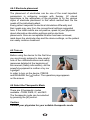
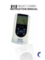
SELECT combo
INSTRUCTION MANUAL
This manual is valid for the InTENSity Select
Combo TENS/IF/MIC/EMS Stimulator
TM
This user manual is published by Current Solutions™, LLC
Current Solutions™, LLC does not guarantee its contents and
reserves the right to improve and amend it at any time without prior
notice. Amendments may however be published in new editions of
this manual.
All Rights Reserved. Rev. V1.1 © 2010
: United States Federal Law restricts this device to sale by
or on the order of a physician or licensed practitioner
Conformity to safety standards
Current Solutions™, LLC declares that the device complies with
following normative document:
IEC60601-1, IEC60601-1-2, IEC60601-2-10,IEC60601-1-4,
ISO10993-5, ISO10993-10, ISO10993-1
Table of Contents
1. SAFETY INFORMATION…..…………………………................ 4
1.1 General description
1.2 Medical background
1.3 Indication for use
1.4 Contraindications
1.5 Warnings, Cautions, Adverse Reactions
2. PRESENTATION…………………………………………………..14
2.1 Front and Rear panel
2.2 LCD display
3.SPECIFICATION………………………………………………...…17
3.1 Accessories
3.2 Technical information
3.3 The waveforms of the stimulation programs
4.INSTRUCTIONS FOR USE ………………………………...…… 23
4.1 Battery
4.2 Connect electrodes to lead wires
4.3 Connect lead wires to device
4.4 Electrodes
4.5 Turn ON
4.6 Select the Therapeutic Mode
4.7 Steps to set a new program
4.8 Adjust Channel Intensity
4.9 Safety Lock Feature
4.10 Stop the treatment
4.11 Turn OFF
4.12 Low battery indicator
5.PROGRAM……………………………………..........................… 33
6.CLEANING AND CARE……………….................................….. 33
6.1 Tips for skin care
6.2 Cleaning the device
6.3 Electrodes
6.4 Cleaning the Electrode cables
6.5 Maintenance
7.TROUBLESHOOTING………………………………….………… 37
8.STORAGE……………………………………………................… 38
9.DISPOSAL………………………………………………….........… 38
10.ELECTROMAGNETIC COMPATIBILITY(EMC)TABLES........ 39
11.GLOSSARY OF SYMBOLS ….............................................. 41
12.WARRANTY………………….................................................. 42
1. Safety information
1.1 General
InTENSity Select Combo is a portable electrotherapy device
featuring four therapeutic modes : Transcutaneous Electrical Nerve
Stimulation (T
TM
pain relief and electrical muscle stimulation. The stimulator sends
gentle electrical current to underlying nerves and muscle groups
via electrodes applied on the skin. The parameters of the device
are controlled by the buttons on the front panel. The intensity level is
adjustable according to the needs of patients.
1.2 Medical background
EXPLANATION OF PAIN
Pain is a warning system and the body’s method of telling us that
something is wrong. Pain is important; without it abnormal
conditions may go undetected, causing damage or injury to vital
parts of our bodies. Even though pain is a necessary warning
signal of trauma or malfunction in the body, nature may have gone
too far in its design.
Aside from its value in diagnosis, long-lasting persistent pain
serves no useful purpose. Pain does not begin until the coded
message travels to the brain where it is decoded, analyzed, and
then reacted to. The pain message travels from the injured area
along the small nerves leading to the spinal cord. Here the
message is switched to different nerves that travel up the spinal
cord to the brain. The pain message is then interpreted, referred
back and the pain is felt.
EXPLANATION OF TENS
Transcutaneous Electrical Nerve Stimulation (TENS) is a noninvasive, drug free method of controlling pain. TENS uses tiny
electrical impulses sent through the skin to nerves to modify your
pain perception. TENS does not cure any physiological problem; it
4
only helps control the pain. TENS does not work for everyone;
however, in most patients it is effective in reducing or eliminating
the pain, allowing for a return to normal activity.
HOW TENS WORKS
There is nothing “magic” about Transcutaneous Electrical Nerve
Stimulation (TENS). TENS is intended to be used to relieve pain.
The TENS unit sends comfortable impulses through the skin that
stimulate the nerve (or nerves) in the treatment area. In many
cases, this stimulation will greatly reduce or eliminate the pain
sensation the patient feels. Pain relief varies by individual patient,
mode selected for therapy, and the type of pain. In many patients,
the reduction or elimination of pain lasts longer than the actual
period of stimulation (sometimes as much as three to four times
longer). In others, pain is only modified while stimulation actually
Occurs. You may discuss this with your physician or therapist.
EXPLANATION OF EMS
Electrical Muscle Stimulation (EMS) is an internationally accepted
and proven way of treating muscular injuries. It works by sending
electronic pulses to the muscle needing treatment; this causes the
muscle to exercise passively. It is a product derived from the
square waveform, originally invented by John Faraday in 1831.
Through the square wave pattern it is able to work directly on
muscle motor neurons. This device has low frequency and in
conjunction with the square wave pattern allows direct work on
muscle groupings. This is being widely used in hospitals and
sports clinics for the treatment of muscular injuries and for the reeducation of paralyzed muscles, to prevent atrophy in affected
muscles and improving muscle tone and blood circulation.
5
HOW EMS WORKS
The EMS units send comfortable impulses through the skin that
stimulate the nerves in the treatment area. When the muscle
receives this signal it contracts as if the brain has sent the signal
itself. As the signal strength increases, the muscle flexes as in
physical exercise. Then when the pulse ceases, the muscle relaxes
and the cycle is repeated.
The goal of electrical muscle stimulation is to achieve contractions
or vibrations in the muscles. Normal muscular activity is controlled
by the central and peripheral nervous systems, which transmit
electrical signals to the muscles. EMS works similarly but uses an
external source (the stimulator) with electrodes attached to the skin
for transmitting electrical impulses into the body. The impulses
stimulate the nerves to send signals to a specifically targeted
muscle, which reacts by contracting, just as it does with normal
muscular activity.
WHAT IS IF?
Interferential Stimulation IF is an anti-inflammatory based treatment
modality. Interferential stimulation is characterized by two
alternating-current sine waves or square waves of differing
frequencies that “work” together to produce an interferential current
that is also known as a beat pulse or alternating modulation
frequency. One of the two currents is usually held at 4,000 Hz, and
the other can be held constant or varied over a range of 4,001 to
4,100 Hz. Because of the frequency, the interferential wave meets
low impedance when crossing the skin to enter deep into soft
tissues. The interferential currents reportedly can stimulate sensory,
motor, and pain fibers. These large impulse fibers interfere with the
transmission of pain messages at the spinal cord level. This deep
tissue penetration stimulates parasympathetic nerve fibers for
increased blood flow and edema reduction. It utilizes the low
electric-current to stimulate muscle nerves to achieve the
symptomatic relief of chronic intractable pain, post-traumatic pain,
and post-surgical pain.
6
WHAT IS MICROCURRENT?
Microcurrent stimulation is a type of therapy in which very low
current is sent into the cells of the body. Microcurrent is a very faint
current that is so small it is measured in millionths of an amp
(Microamps). Human cells generate a current that is in the micro
amp range which is why you can’t feel it - the current is so low it
doesn’t stimulate the sensory nerves.
Microcurrent is a physiological electric modality that increases ATP
(energy) production in the cells of your body. This dramatically
increases the tissue’s healing rate. The immediate response to the
correct microcurrent frequency suggests that other mechanisms
are involved as well. The exact effects or changes in the tissue are
unmistakable; scars will often suddenly soften; trigger points often
become less painful within minutes when the “correct” frequency is
applied. In many situations the changes seen seem to be long
lasting and in many cases permanent.
1.3 Indication for use
InTENSity Select Combo TENS/EMS/IF/MIC Stimulator may be
used for the following conditions:
TM
For Transcutaneous Electrical Nerve Stimulator / Interferential/
Microcurrent therapeutic modes (TENS/IF/MIC)
1) Symptomatic relief of chronic pain
2) Post traumatic pain
3) Post surgical pain
For Electrical Muscle Stimulation / Neuromuscular Stimulation
therapeutic mode (EMS)
1) Relaxation of muscle spasms
2) Increase of blood flow circulation
3) Prevention of disuse atrophy
4) Muscle re-education
5) Maintaining or increasing range of motion
6) Immediate post-surgical stimulation of lower leg muscles to
prevent venous thrombosis
7
IMPORTANT SAFETY INFORMATION!
Read the instruction manual before operation. Be sure to comply
with all “Contraindications”, “Warnings”, “Cautions” and “Adverse
reactions” in the manual. Failure to follow instructions can cause
harm to user or device.
1.4 Contraindications
1.5 Warnings, Cautions and Adverse Reactions
WARNINGS:
9
CAUTIONS:
1) Federal law (USA) restricts this device to sale by or on the
order of a physician.
2) For single patient use only.
3) Keep yourself informed of the contraindications.
4) This stimulator not intended for unattended, personal use by
patients who have noncompliant, emotionally disturbed,
dementia, or low IQ.
5) Read, understand, and practice the warnings, cautions and
operating instructions. Know the limitations and hazards
associated with using any device. Observe the cautionary and
operational decals placed on the unit. Always follow the
operating instructions prescribed by your healthcare
practitioner.
6) The instruction of use was listed; any improper use may be
dangerous.
7) Do not use this device for undiagnosed pain syndromes until
consulting a physician.
8) Patients with an implanted electronic device, such as a cardiac
pacemaker, implanted defibrillator, or any other metallic or
electronic device should not use this device without first
consulting a doctor.
9) Stimulation delivered by this device may be sufficient to cause
electrocution. Electrical current of this magnitude must not flow
through the thorax or across the chest because it may cause a
cardiac arrhythmia.
10) Do not place electrodes on the front of the throat as spasm of
the Laryngeal and Pharyngeal muscle may occur. Stimulation
over the carotid sinus (neck region) may close the airways,
make breathing difficult, and may have adverse effects on the
heart rhythm or blood pressure.
11
14) Electrode placement and stimulation settings should be based
on the guidance of prescribing practitioner.
15) Effectiveness is highly dependent upon patient selection by a
person qualified in the management of pain afflicted patients.
16) Isolated cases of skin irritation may occur at the site of the
electrode placement following long-term application. If this
occurs, discontinue use and consult your physician.
17) The electrodes are only to be placed on healthy skin. Avoid
skin irritation by ensuring that good contact is achieved
between electrodes and skin.
18) If the stimulation levels are uncomfortable or become
uncomfortable, reduce the stimulation Intensity to a
comfortable level and contact your physician if problems persist.
19) This device should not be used while driving, operating
machinery, close to water, or during any activity in which
involuntary muscle contractions may put the user at undue risk
of injury.
20) Never use the device in rooms where aerosols (sprays) are
used or pure oxygen is being administered.
21) Do not use it near any highly flammable substances, gases or
explosives.
22) Do not use this device at the same time as other equipment
which sends electrical pulses to your body.
23) Do not confuse the electrode cables and contacts with your
headphones or other devices, and do not connect the
electrodes to other devices.
24) Do not use sharp objects such as pencil point or ballpoint pen
to operate the buttons on the control panel.
25) Inspect Applicator cables and associated connectors before
each use.
26) Turn the device off before applying or removing electrodes.
27) Electrical stimulators should be used only with the leads and
electrodes recommended for use by the manufacturer.
28) This device has no AP/APG protection. Do not use it in the
presence of explosive atmosphere and flammable mixture.
12
Adverse Reactions:
1) Skin irritation from the electrode gel and electrode burns are
potential adverse reactions. If skin irritation occurs,
discontinue use and consult your physician.
Note: Always use electrodes that are legally marketed and
sold in the United States under 510K guidelines.
2) If the stimulation levels are uncomfortable, reduce the
stimulation Intensity to a comfortable level and contact your
physician if any problems persist.
13
2. Presentation
2.1 Front and Rear Panel
1)
2)
3)
4)
5)
6)
7)
Output socket: electric signal output after connection of the
cable with adhesive electrodes on channel 1.
Output socket: electric signal output after connection of the
cable with adhesive electrodes on channel 2.
Increasing the output intensity of channel 1 [▲]. Use to set
the application program and the parameter of the waveform in
the setting state.
Decreasing the output intensity of channel 1 [▼]. Use to set
the application program and the parameter of the waveform
in the setting state and to unlock the current treatment
program.
Therapeutic mode selection. Stop the treatment. Exit setting
mode to return to the user interface.
LCD display: Shows the operating state of the device.
Increasing the output intensity of channel 2 [▲]. Use to set
the application program and the parameter of the waveform in
the setting state.
14
8)
9)
10)
11)
12)
13)
Decreasing the output intensity of channel 2 [▼]. Use to set
the application program and the parameter of the waveform
in the setting state. Use to unlock the current treatment
program.
Parameter Selection: press the button to enter setting state;
you can select the different parameters in conjunction with
[▲] and [ ▼].
Press [ ] to turn ON. Press [ ] button and hold for
approximately 3 seconds to turn off the device.
Belt Clip.
The battery compartment cover for user access.
Adapter Receptacle.
2.2 LCD display
1)
2)
3)
4)
5)
6)
7)
8)
Displays therapeutic mode.
Displays therapeutic program for TENS and EMS therapeutic
mode.
Displays therapeutic program for IF and MIC therapeutic mode
or displays the cycle time for TENS, IF and MIC therapeutic
mode in setting state.
Timer symbol.
EMS waveform of ramp up and ramp down time.
Display of waveform pulse width.
Displays channel 1.
Display of the output intensity for channel 1 (CH1); Display of
waveform pulse width or EMS waveform of contraction
(working) time in setting state.
3. Specification
3.1 Accessories
3.2 Technical information
Channel
Power supply
Dual, isolated between channels
9.0 V Alkaline DC -1 *6LR61 battery
Adapter output: 9.0Vdc, 800mA(optional)
5°C to 40°C (41℉ to 104℉)with a relative
Operating conditions humidity of
-10°C to 50°C (14℉ to 122℉)with a relative
Storage conditions
humidity of
Dimensions
4.5×2.55×0.9 inches(L*W*H)
Weight
Tolerance
0.28 lbs(With battery)
There may be a ±5% tolerance of all setting
and ±10%
Adjustable from 1 to 60 minutes or continuous.
Adjusts in 1 minute steps. Treatment time
countdown is automatic.
The amplitude level will be reset to 0mA when the
amplitude level is 12mA or greater and an open
circuit at either channel is detected.
Timer
Electrode Detection
Function
Technical specifications for Transcutaneous Electrical Nerve
Stimulator (TENS) mode
Waveform
Mono-phase square pulse wave
Pulse amplitude Adjustable, 0~105mA peak at 1000 ohm Load
each channel, 1mA/Step.
Pulse Width
Adjustable,from 50 to 300us microseconds ,10μS/step
Pulse Rate
Adjustable, from 1 to 150 Hz , 1 Hz/step
Burst (B)
Burst rate: Adjustable, 0.5 ~ 5Hz
Pulse width adjustable, 50~300μS
Frequency fixed = 100 Hz
Normal (N)
The pulse rate and pulse width are adjustable. It
generates continuous stimulation based on the
setting value.
Pulse Width
Modulation (M)
The pulse width is automatically varied in a
cycle time. The pulse width is decreased from
its original setting to 60% in setting cycle time,
and then increased from 60% to its original
setting in nest setting cycle time. In this
program, pulse rate (1 to 150Hz), pulse width
(50 to 300us) and cycle time (5 to 30 sec) are
fully adjustable.
Pulse Rate
The pulse rate is automatically varied in a cycle
Modulation (M1) time. The pulse rate is decreased from its
original setting to 60% in setting cycle time, and
then increased from 60% to its original setting in
nest setting cycle time. In this program, pulse
rate (1 to 150Hz), pulse width (50 to 300us) and
cycle time (5 to 30 sec) are fully adjustable.
18
Technical specifications for Electrical Muscle Stimulation
(EMS) mode
Waveform:
Pulse amplitude
Pulse Width
Pulse Rate
Contraction time
Relaxation (OFF)
Ramp time
Synchronous (S)
Alternate (A)
Delay (D)
Mono-phase square pulse wave
Adjustable, 0~105mA peak at 1000 ohm Load
each channel, 1mA/Step.
Adjustable, from 50 to 300μS microseconds,
10μS/step.
Adjustable, from 1 to 150 Hz, 1 Hz/step
Adjustable, 1~60 seconds , 1 Sec./ step
Adjustable, 0~60 seconds , 1 Sec./ step
Adjustable, 1~6 seconds, 1 Sec. / step, The
“On” time will increase and decrease in the
setting value.
Stimulation of both channels occurs
synchronously. The“ON” time including
“Contraction”, “Ramp Up” and “Ramp Down”
time.
ON TIME=Contraction + Ramp up + Ramp
dow
The Stimulation of the CH2 will occur after the
1st working of CH1 is completed. In this
program, The “ON” time including “Contraction”,
“Ramp Up” and “Ramp Down” time. The OFF
Time should be equal or more than the ON
Ti
TI
Ramp down
OFF TIME≥ON TIME
The Stimulation of the CH2 will occur after the
1st operation of CH1 is started+ Delay Time. In
this program, The “ON” time including
“Contraction”, “Ramp Up” and “Ramp Down”
time. The OFF Time should be equal or more
than the ON Time + Delay Time.
ON TIME=Contraction + Ramp up + Ramp
down
Technical specifications for Interferential (IF) mode
Waveform
Pulse amplitude
Pulse Rate
Phase Width
Bi-phase square pulse
Adjustable, 0~70mA peak to peak at 1000 ohm Load
Channel 1 – Fundamental frequency: 4000 Hz fixed
Channel 2 – Selectable frequency: 4001 to 4150 Hz
Interference frequency: 1 to 150 Hz.
125μS
Technical specifications for Microcurrent (MIC) mode
Waveform
Pulse amplitude
Mono-phase square pulse wave
Adjustable, 0~0.7mA peak at 1000 ohm Load each
channel, 0.01mA/Step
Pulse Width (P.W.) Adjustable, from 2 to 200ms, 1ms/step
Pulse Rate (P.R.)
Adjustable, from 1 to 150 Hz, 1 Hz/step
Constant(P1)
Constant stimulation based on setting value. Only
pulse width, pulse rate and timer are adjustable in
this program. “Constant” is equal to the “Normal”
mode of a TENS therapeutic mode
The pulse width is automatically varied in a cycle
time.The pulse width is decreased from its original
setting to 60% in setting cycle time, and then
increased from 60% to its original setting in nest
setting cycle time. In this program, pulse rate (1 to
150Hz), pulse width (2 to 200ms) and cycle time (5 to
30 sec) are fully adjustable.
The pulse rate is automatically varied in a cycle time.
The pulse rate is decreased from its original setting
to 60% in setting cycle time, and then increased from
60% to its original setting in nest setting cycle time. In
this program, pulse rate (1 to 150Hz), pulse width (2
to 200ms) and cycle time (5 to 30 sec) are fully
adjustable.
Pulse Width
Modulation (P2)
Pulse Rate
Modulation (P3)
20
3.3 The waveforms of the stimulation programs
Burst (B)
Normal (N)
Pulse Width Modulation
Pulse Rate Modulation
Synchronous(S)
Alternate (A)
Delay (D)
Interferential
Microcurrent (Constant)
22
4. Instructions for use
4 .1 Battery
4.1.1 Check/Replace the battery
Over time, in order to ensure the
functional safety of device, the battery
must be periodically changed.
1) Slide the battery compartment cover
and open.
2) Insert the 9V battery into the battery
compartment.
3) Make sure you are installing the battery properly. Be sure to
match the positive and negative ends of the battery to the
marking in the battery compartment of the device.
4) Press and pull down following the direction of the arrow
indicated on the photo.
5) Replacing the battery compartment cover and press to close
6) If replacing the battery, you should slide the battery compartment
cover and open. Pull up the battery following the direction of
the arrow indicated on the photo. And insert the 9V battery
according to the above steps 2 - 5.
4.1.2 Disposal of battery
Spent batteries do not belong in household waste.
Dispose of the battery according to the current federal,
state and local regulations.
Caution:
1) Battery may be fatal if swallowed. Therefore, keep the
battery and the product out of the range of children, if a
battery was swallowed, consult a physician immediately.
2) If a battery has leaked, avoid contact with skin, eyes and
mucus membranes. Rinse the affected spots with clear
water immediately and contact a physician right away.
3) Battery may not be charged, dismantled, thrown into fire
or short-circuited.
4) Protect battery from excess heat; Take the battery out of
the product if they are spent or in case you no longer
use the article. This prevents damage caused by leaking
battery.
5) Always replace the same type battery.
4.2 Connect electrodes to lead wires
Insert the lead wire connector into
electrode connector (standard 0.08 inch
female connection). Make sure there are
no bare metal of the pins exposed.
Caution:
Always use the electrodes with the
requirements of the IEC/EN60601-1,ISO10993-1/-5/-10 and
IEC/ EN60601-1-2, such as with CE mark, or which are legally
marketed in the US under 510(K) listing.
4.3 Connect lead wires to device
1) Before proceeding to this step, be sure the device is completely
turned OFF.
2) Insert the wires provided with the system into the jack sockets
located on top of the device.
3) Holding the insulated portion of the connector, push the plug
end of the wire into one of the jacks (see drawing); one or
two sets of wires may be used.
4) This device has two output receptacles controlled by Channel
1 and Channel 2 at the top of the unit. You may choose to use
one channel with one pair of lead wires or both channels with
two pairs of lead wires. Using both channels gives the user the
advantage of stimulating two different areas at the same time.
Caution:
Do not insert the plug of the patient
lead wire into any AC power supply
socket.
24
4.4 Electrode
4.4.1 Electrode options
The electrodes are disposable and should be routinely replaced
when they start to lose their adhesive nature. If you are unsure of
your electrodes adhesive properties, order replacement electrodes.
Replacement electrodes should be re-ordered through or on the
advice of your physician to ensure proper quality. Follow application
procedures outlined in electrode packing, to maintain optimal
stimulation and to prevent skin irritation.
4.4.2 Place electrodes on skin
Apply electrodes to the exact site indicated by your physician or
therapist. Before applying electrodes, be sure the skin surface over
which electrodes are placed is thoroughly clean and dry. Make sure
the electrodes are pressed firmly to the skin and make good contact
between the skin and the electrodes. Place the electrodes over the
skin; attach them properly, firmly, and evenly.
Caution:
1) Before applying the self-adhesive electrodes, it is
recommended to wash and degrease and dry the skin.
2) Do not turn on the device when the self-adhesive
electrodes are not positioned on the body.
3) Never remove the self-adhesive electrodes from the skin
while the device is turned on.
4) It is recommended that, at minimum, 1.5” x 1.5” selfadhering based, square electrodes are used at the
treatment area
25
4.4.3 Electrode placement
The placement of electrodes can be one of the most important
parameters in achieving success with therapy. Of utmost
importance is the willingness of the physician to try the various
styles of electrode placement to find which method best fits the
needs of the individual patient.
Every patient responds to electrical stimulation differently and
their needs may vary from the conventional settings suggested
here. If the initial results are not positive, speak to your physician
about alternative stimulation settings and/or electrode
placements. Once an acceptable location has been achieved,
mark down the electrode sites and the device settings, so the patient
can easily continue treatment.
4.5 Turn on
Before using the device for the first time,
you are strongly advised to take careful
note of the contraindications and safety
measures detailed at the beginning of
this manual (Safety information), as this
powerful equipment is neither a toy nor
a gadget!
In order to turn on the device, PRESS
and RELEASE the [ ] button. The operation page appears
on the screen.
4.6 Select the Therapeutic Mode
There are 4 therapeutic modes
available –TENS, EMS, IF, and MIC.
The therapeutic mode can be selected
by pressing the [M] control.
Caution:
Consult your physician for your suitable therapeutic mode
4.7 Steps to Set a New Program
4.7.1 TENS Setting
Press the [S] button cycle to enter the setting state. The settings
can be adjusted according to the following steps:
1) Set the Therapeutic Program
There are 4 programs in TENS therapeutic
mode available –Burst (B), Normal (N), Pulse
Width Modulation (M), and Pulse Rate
Modulation (M1). The therapeutic program can
be selected by pressing the [▲] and [▼] button.
When you choose to “B” program, program “B”
outside of the box will be flashing.
2) Set Cycle Time (Optional)
Cycle time is adjustable from 5 to 30 seconds. Only modulation
has this parameter setting. Press [S] button cycle to enter this
menu, and then press the [▲]and [▼]button to adjusting the
setting.
3) Set Timer
Press [S] button cycle to enter this setting. The treatment time is
adjustable from 1 to 60 minutes or Continuous. Press [▲] or [▼]
button control to adjust setting. You can set the timer to
“Continuous” mode by pressing the [▲] control when it shows 60
minutes. The output will be shut off when time is up.
4) Set Pulse Width
Pulse Width is adjustable from 50 uS to 300 uS. Press [S] button to
enter this menu, then press [▲] or [▼] button to adjust the setting.
5) Set Pulse Rate
Pulse rate is adjustable from 1 Hz to 150 Hz (0, 5 Hz to 5 Hz for
Burst). Press [S] button cycle to enter this menu, and then press
[▲] or [▼] button to adjust the setting.
27
4.7.2 EMS Setting
Press the [S] button cycle to enter the setting state. The settings
can be adjusted according to the following steps:
1) Set the Therapeutic Program
There are 3 programs in EMS therapeutic
mode available – Synchronous, Alternate and
Delay. The therapeutic program can be
selected by pressing the [▲] and [▼] button.
When you choose to [S] program, program [S]
outside of the box will be flashing.
2) Set Timer
Press [S] button cycle to enter this setting. The treatment time is
adjustable from 1 to 60 minutes or Continuous. Press [▲] or [▼]
control to adjust setting. You can set the timer to “Continuous”
mode by pressing the [▲] button when it shows 60 minutes. The
output will be shut off when time is up.
3) Set Pulse Width
The pulse width determines the length of time. Each electrical
signal is applied through the skin, which controls the strength and
sensation of the stimulation. Press [S] button cycle to enter this
setting. The pulse width is adjustable from 50 to 300 uS.
Press [▲] or [▼] button to adjust the setting.
4) Set Pulse Rate
The pulse rate determines how many electrical impulses are
applied through the skin each second. Press [S] button cycle to
enter this menu. Adjust the setting by pressing the [▲] or [▼]
buttons. The pulse rate is adjustable from 1 Hz to 150 Hz.
5) Set Delay Time (Optional)
Delay time is adjustable form 1 to 10 seconds.
Only the “Delay” therapeutic program has this
parameter setting. Press [S] button cycle to
enter this menu, and then press the [▲] and [▼]
button to adjusting the setting.
6) Set Ramp Time
The ramp time controls the time of output current that increase from
0 to the setting level, and from the setting value to 0. When the
ramp time is set, each contraction may be ramped up and down in
order that the signals come on and come off gradually and smoothly.
The ramp time is adjustable from 1 to 6 seconds.
7) Set Contract Time
The contract Time controls the time of stimulation and can be
adjusted. Press [S] button cycle to enter this menu, and then press
the [▲] and [▼] button to adjust the setting. Both channels’
stimulation is cycled on and off by the contraction and relaxation
settings. The range is adjustable from 1 to 60 seconds.
Caution:
Contract time does not include the ramp up and ramp down
time, ON time=Ramp up + Contract time + Ramp down.
8) Set Relaxation (OFF) time
The Off Time controls the time of relaxation and can be adjusted.
Press [S] button cycle to enter this menu, and then press the [▲]
and [▼] button to adjusting the setting. Both channels’ stimulation
is cycled on and off by the contraction and relaxation settings. The
range is adjustable from 0 to 60 seconds.
In Alternate program, the OFF Time should be equal or more than
the ON Time. (OFF TIME ≥ ON TIME)
4.7.3 IF Setting
Press the [S] button to enter the setting state. The settings can be
adjusted according to the following steps:
1) Set the Therapeutic Program
There are 4 programs in IF therapeutic mode
available. The therapeutic program can be
selected by pressing the [▲] and [▼] button.
The mode you selected will show up on the
top of liquid crystal display.
2) Set Timer
Press [S] button cycle to enter this setting.The treatment time is
adjustable from 1 to 60 minutes or Continuous.
29
Press [▲] or [▼] control to adjust setting. You can set the timer to
“Continuous” mode by pressing the [▲] button when it shows 60
minutes. Its output will be shut off when time is up.
3) Set Interference frequency (optional)
Channel 1 has 4000 Hz fixed Fundamental frequency. Channel has
selectable frequency from 4001 to 4150Hz; Interference frequency
is adjustable form 1 Hz to 150 Hz. Only “P4” has this parameter
setting. Press [S] button cycle to enter this menu, and then press
the [▲] and [▼] button to adjusting the setting.
4) Set Cycle Timer
Cycle time is adjustable form 5 to 30 seconds. Press [S] button
cycle to enter this menu, and then press the [▲] and [▼] button to
adjusting the setting.
4.7.4 Microcurrent Setting
Press the [S] button cycle to enter the setting state. The settings
can be adjusted according to the following steps:
1) Set the Therapeutic Program
There are 3 programs in MIC therapeutic program
available: Constant, Pulse Width Modulation, and
Pulse Rate Modulation.
The therapeutic program can be selected by
pressing the [▲] and [▼] button. The mode you
selected will show up on the top of LCD Display.
2) Set Timer
Press [S] button cycle to enter this setting. The treatment time is
adjustable from 1 to 60 minutes or Continuous. Press [▲] or [▼]
button control to adjust setting. You can set the timer to
“Continuous” mode by pressing the [▲] control when it shows 60
minutes. Its output will be shut off when time is up.
3) Set Pulse Width
Pulse Width is adjustable from 2ms to 200ms. Press [S] button cycle
to enter this menu, then press [▲] or [▼]button to adjust the setting.
4) Set Pulse Rate
Pulse rate is adjustable from 1 Hz to 150 Hz. Press [S] button cycle
to enter this menu, and then press [▲] or [▼]button to adjust the
setting.
5) Set Cycle Time (Optional)
Cycle time is adjustable form 5 to 30 seconds.
Only modulation mode has this parameter
setting. Press [S] button cycle to enter this
menu, and then press the [▲] and [▼] button to
adjusting the setting.
4.8 Adjust Channel Intensity
Press the intensity control button ([▲] and [▼]) to control the
intensity output. Slowly press the intensity button control until you
reach the setting recommended by your physician or therapist.
Repeat for the other channel, if both channels are to be used.
Caution:
1) If the stimulation levels are uncomfortable or become
uncomfortable, reduce the stimulation intensity to a
comfortable level and contact your medical practitioner
if problems persist.
2) TENS, EMS and IF therapeutic mode. If the electrodes are
not placed firmly on skin or the device is not connected to
the electrodes and the stimulator’s output intensity
surpasses 12mA, the intensity will automatically reset to
0mA.
4.9. Safety Lock Feature
The Safety Lock Feature automatically activates after there is no
operation in the panel for 30 seconds by locking out the ability to
press the buttons. This is a safety feature to prevent accidental
changes to your settings and to prevent accidental increases to the
intensity levels. You can press either one of the [▼] buttons to
unlock the device.
31
4.10. Stop the treatment
When you have activated the treatment timer,you can press the [M]
button or the [▼] button to control stop the treatment.
Caution:
Default state, if the button is locked, you can press only one of
the [▼] buttons to unlock, and then press the [M] button or the
[▼] button to control stop the treatment.
4.11. Turn OFF
PRESS [ ] button and HOLD for approximately 3 seconds to turn
OFF the device.
Caution:
1) If there is no operation in the panel for 2 minutes in the
waiting state, the device turns off automatically.
2) In shutdown state, keep pressing the channel 2 [▼] first,
and then press [ ] button at the same to restore factory
parameter settings
4.12. Low battery indicator
When the low power indicator flashes, the device will be turns off
automatically, the battery should be replaced with a new one as
soon as possible. However, the unit may continue to operate for an
extended period of time depending on the setting and intensity
level.
5. Program
Mode Program Modulation Frequency
Method
Pulse
Width
Treatment time
1-150Hz
50-300us
50-300us
1-60min,continuous
1-60min,continuous
1-150Hz
50-300us
1-60min,continuous
1-150Hz
50-300us
1-60min,continuous
1-150Hz
50-300us
1-60min,continuous
4kHz
4001-4010Hz
125us
1-60min,continuous
125us
1-60min,continuous
modulation
4kHz
4001-4150Hz
4kHz
4080-4150Hz
modulation
4kHz
4001-4150Hz
125us
1-60min,continuous
1-150Hz
2-200ms
1-60min,continuous
1-150Hz
2-200ms
1-60min,continuous
TENS
d l ti
modulation
EMS
mode
Mode
modulation
IF
MIC
modulation
modulation
modulation
125us
1-60min,continuous
6. Cleaning and Care
6.1 Tips for skin care
To avoid skin irritation, especially if you have sensitive skin, follow
these suggestions:
1) Wash the area of skin where you will be placing the
electrodes, using mild soap and water before applying
electrodes, and after taking them off. Be sure to rinse soap
off thoroughly and dry skin well.
2) Excess hair may be clipped with scissors; do not shave
stimulation area.
33
3) Wipe the area with the skin preparation your clinician has
recommended. Let this dry. Apply electrodes as directed.
4) Many skin problems arise from the “pulling stress” from
adhesive patches that are excessively stretched across the skin
during application. To prevent this, apply electrodes from center
outward; avoid stretching over the skin.
5) To minimize “pulling stress”, tape extra lengths of lead wires to
the skin in a loop to prevent tugging on electrodes.
6) When removing electrodes, always remove by pulling in the
direction of hair growth.
7) It may be helpful to rub skin lotion on electrode placement area
when not wearing electrodes.
8) Never apply electrodes over irritated or broken skin.
6.2 Cleaning the device
1) Remove the battery from the device every time when you clean
the device.
2) Clean the device after use with a soft, slight moistened cloth.
In case of more extreme soiling you can also moisten the
cloth with mild soapy water.
3) Do not use any chemical cleaners or abrasive agents for
cleaning.
6.3 Electrodes
1) Use the device only with the leads and electrodes provided by
the manufacturer. Use only the electrode placements and
stimulation settings prescribed by your physician or therapist.
2) It is recommended that, at minimum, 1.5” x 1.5” self-adhering
electrodes should be used at the treatment area.
3) Inspect your electrodes before every use. Replace electrodes
as needed. Reusable electrodes may cause slight skin irritation,
lose adhesion properties and deliver less stimulation if
overused.
34
To use these electrodes:
1)
2)
3)
Attach the electrode to the lead wire.
Remove the protective backing from the electrode surface.
Do not throw away the protective backing because it is
reused after the treatment session has been completed.
Place the tacky surface to the prescribed skin area by pressing
the electrode firmly against the skin.
To remove your electrodes:
1)
Lift the corner of the electrode and gently remove it from the
skin.
2) It may be helpful to improve repeated application by
spreading a few drops of cold water over the adhesive and
turn the surface up to air dry. Over Saturation with water
will reduce the adhesive properties.
3) Between uses, store the electrodes in the resealable bag in a
cool dry place.
Caution:
1) Do not pull on the electrode wire. Doing so may damage
the wire and electrode.
2) Do not apply to broken skin.
3) The electrodes should be discarded when they are no
longer adhering.
4) The electrodes are intended for single patient use only.
5) If irritation occurs, discontinue use and consult your
clinician.
6) Read the instructions for use of self-adhesive electrodes
before application.
35
7) Always use the electrodes with the requirements of the
IEC/EN60601-1, ISO10993-1/-5/-10 and IEC/ EN60601-1-2,
such as with CE mark, or are legally marketed in the US
under 510(K) procedure.
6.4 Cleaning the Electrode's cords
Clean the electrode cords by wiping them with a damp cloth. Coating
them lightly with talcum powder will reduce tangles and prolong the
life.
6.5 Maintenance
1) Maintenance and all repairs should only be carried out by an
authorized agency. The manufacturer will not be held
responsible for the results of maintenance or repairs by
unauthorized persons.
2) The user must not attempt any repairs to the device or
accessories. Please contact the retailer for repair.
3) Opening of the equipment by unauthorized agencies is not
allowed and will terminate any claim to warranty.
4) Check the unit before each use for signs of wear and/or damage.
Replace worn items as required.
7. Troubleshooting
If your device does not seem to be operating correctly, refer to
the chart below to determine what may be wrong. Should none
of these measures correct the problem, the device should be
serviced.
Proble
Display fails to
light up
Possible Cause
Battery contact failure
Solution
1. Try fresh batteries.
2. Ensure batteries are inserted
correctly.
Check the following:
• All contacts are in place
• All contacts are not broken
Stimulation weak Electrodes / Lead Wires
Replace and re-connect
1. Dried out or contaminated Follow instruction manual
2. Placement of lead wires Follow instruction manual
3. Old/worn/damaged lead Replace
wires or electrodes
Stimulation is
uncomfortable
Intensity is too high
Electrodes are too
close together
Decrease intensity.
Reposition the electrodes.
Damaged or worn
electrodes or lead wires
Replace.
Electrode active area size
is too small.
Lead wires
Replace electrodes with ones that
have an active area no less than
1. Verify connection is secure & firmly
seated
2. Turn down the intensity. Rotate
lead wires in socket 90°. If still
intermittent, replace lead wire.
3. If still intermittent after replacing
lead wire, a component may have
failed. Call the repair department.
Program option in use
Some programs will seem
intermittent. This is expected.
Refer to the Program Option
Controls in the Operation section for
a description of the program option.
Improper electrode and
applicator placement
Unknown
Reposition electrode and applicator
Contact clinician.
Intermittent
output
Stimulation is
ineffective.
37
8. Storage
1)
For a prolonged pause in treatment, store the device in a dry
room and protect it against heat, sunshine and moisture and
remove the battery.
2) Store the device in a cool, well-ventilated place
3) Never place any heavy objects on the device.
9. Disposal
Used fully discharged batteries must be disposed of in a
specially labeled collection container, at toxic waste
collection points or through an electrical retailer.
Please dispose of the device in accordance with the law.
38
10. Electromagnetic Compatibility (EMC) Tables
Guidance and manufacturer’s declaration - electromagnetic emissions
The device is intended for use in the electromagnetic environment specified
below. The
Emissions test
Compliance
Electromagnetic environment - guidance
RF emissions
Group 1
The device uses RF energy only for its
internal function. Therefore, its RF emissions
CISPR 11
are very low and are not likely to cause any
interference in nearby electronic equipment.
RF emissions
CISPR11
Class B
Harmonic
emissions
lEC 61000-3-2
Voltage
fluctuations
/ flicker
emissions lEC
61000-3-3
The device is suitable for use in all
establishments other than domestic and
Not applicable those directly connected to the public lowvoltage power supply network that supplies
buildings used for domestic purposes.
Not applicable
Guidance and manufacturer’s declaration — electromagnetic immunity
The device is intended for use in the electromagnetic environment specified
below. The customer or the user should assure that it is used in such an
environment.
Immunity test
IEC 60601
test level
Electrostatic
±6 kV contact
discharge
(ESD)
±8 kV air
lEC 61000-4-2
Compliance
level
Electromagnetic environment guidance
±6 kV contact Floors should be wood, concrete
or ceramic tile. If floors are
±8 kV air
covered with synthetic material,
the relative humidity should be at
least 30 %.
39
Guidance and manufactu
m
urer’s decllaration. Electromag
E
gnetic imm
munity
The de
evice is inte
ended for use in the electromagnetic envvironment sspecified below.
b
The cu
ustomer or the
Immun
nity IEC 60501
6
mpliance
Com
test
test le
evel Levvel
Electroma
agnetic environment - guidance
e
Portable and
a mobile
e RF comm
munications
equipmen
nt should be
b used no
o closer to any
part of the
e device, in
ncluding ca
ables, than
n the
recomme
ended sepa
aration disttance calcu
ulated
from the equation
e
a
applicable
tto the frequ
uency
of the tran
nsmitter.
Recomme
ended sep
paration disstance.
Condu
ucted 3 Vrm
ms
3 Vrrms
RF lEC
C
150 kHz
k
to
61000--4-6 80 MH
Hz
Radiatted 3 V/m
m80
3 V//m
RF lEC
MHz to
t
61000--4-3 2.5 GHz
800MHz to 2,5MHz
t
80MHz to 800MHz
Where P is the maxximum outp
put power rating
of the tran
nsmitter In
n watts (W)) according
g to
the. Trans
smitter ma
anufacturerr and d Is the
t
recomme
e
(m).
Field stre
engths from
m fixed RF transmitte
ers, as
determine
ed by an electromagnetic site survey,
s
ce level in
should be
e less than
n the complianc
each frequ
uency rang
ge.
Interferen
nce may occcur In the vicinity of
equipmen
nt marked with the fo
ollowing symbol:
NOT
TE I At 80 MHz
M
ends 800 MHz. the higherr frequencyy range applies.
NOT
TE 2 These
e guideliness may not apply in alll situationss. Electrom
magnetic
propa
agation is affected byy absorptio
on and reflection from
m structure
es, objects
and people.
p
1. Field
d strengthss from fixed transmittters, such as base sttations for radio
(cellu
ular/cordlesss) telepho
ones
and land
l
mobile radios, amateur
a
radio, AM an
nd FM radio broadcast and TV
broad
dcast cann
not be pred
dicted theo
oretically with
w accuraccy. To assess the
electtromagnetic environm
ment due to
o fixed RF transmitte
ers, an elecctromagnetic site
surve
ey should be
b conside
ered. If the measured
d field stren
ngth in the location in
n which
the device
d
is ussed exceed
ds the app
plicable RF
F compliancce level ab
bove, should be
obse
erved to verify
norm
mal operatio
on. If abno
ormal perfo
ormance is observed, additiona
al measures may
be ne
ecessary, such
s
as re
eorienting or
o relocatin
ng the device.
2. Ove
er the frequ
uency rang
ge 150 kHzz to 80 MHz, field stre
engths sho
ould be less than
[Vi] V/m.
V
40
Recomm
mended se
eparation distances
d
b
between
portable and mobille RF communication
ns equipme
ent and the
e device
The device
d
is intended forr use in an electroma
agnetic envvironment iin which ra
adiated
RF dissturbancess are contrrolled. The customer or the use
er of the de
evice can help
h
prevent electrom
magnetic in
nterference
e by mainta
aining a minimum disstance betw
ween
portab
ble and mo
obile RF co
ommunicattions equip
pment (tran
nsmitters) a
and the as
s
recom
mmended below,
b
acco
ording to the maximu
um output power of th
he
comm
municationss equipmen
nt.
Rate
ed maximum
outtput powerr
of tra
ansmitter
W
0,0
01
0,,1
1
10
0
10
00
Separattion distanc
ce according to frequ
uency of
transmitter
t
r
15
50 kHz to 8
MH
Hz
MHz
M to 800
0
MH
Hz
0.12
0.38
1.2
3.8
12
800 M
MHz to 2,5 GHz
0.12
0
0.38
1.2
3.8
12
0.23
0.73
2.3
7.3
23
For tran
nsmitters ra
ated at a maximum
m
o
output
pow
wer not liste
ed above, tthe
recomm
mended separation distance d in meters (m) can be estimated
d using the
equation applicab
ble to the frrequency of
o the trans
smitter, where P is th
he maximum
p
ratin
ng of the trransmitter in watts (W
W) accorda
able to the transmitterr
output power
manufa
acturer.
NOTE I At 80 MHz and 800 MHz. the separation
n distance for the higher freque
ency
range applies.
a
NO
OTE 2 These guidelin
nes may no
ot apply in all situatio
ons.
Electrom
magnetic propagatio
p
n is affecte
ed by
absorpttion and re
eflection fro
om structurres, objects and peop
ple.
ossary of Symbols
S
11. Glo
c
01000001
Batch code……..0
Serial number……
n
…50000001
Attentio
on: Read th
he operatin
ng instruction for use!
Electrica
al devices are recyclable material and sh
hould not be
dispose
ed of with household
h
er their use
eful life! He
elp us
waste afte
to prote
ect the enviironment and
a save re
esources a
and take th
his
device to
t the apprropriate collection po
oints. Pleasse contact the
organiza
ation which
h is respon
nsible for waste
w
dispo
osal in you
ur area
if you ha
ave any qu
uestions.
Degree of Electriccal Protectiion BF
12. Warranty
Please contact your dealer in case of a claim under the
warranty. If you have to send the unit back to your provider,
enclose a copy of your receipt and state what the defect is.
The following warranty terms apply:
1) The warranty period for device is one year from date of
purchase. In case of a warranty claim, the date of purchase
has to be proven by means of the sales receipt or invoice.
2) Repairs under warranty do not extend the warranty period
either for the device or for the replacement parts.
3) The following is excluded under the warranty:
·All damage which has arisen due to improper treatment, e.g.
nonobservance of the user instruction.
·All damage which is due to repairs or tampering by the
customer or unauthorized third parities.
·Damage which has arisen during transport from the
manufacturer to the consumer or during transport to the
retailer.
·Accessories which are subject to normal wear and tear.
4) Liability for direct or indirect consequential losses caused by
the unit is excluded even if the damage to the unit is accepted
as a warranty claim.
42
Manufactured for:
Current Solutions LLC
3814 Woodbury Drive
Austin,TX 78704
Ph:(800)871-7858
www.currentsolutionsnow.com
TM