1
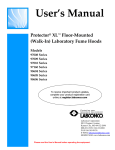
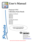
User’s Manual
Protector® Laboratory Fume Hoods
XL™ Floor-Mounted (Walk-In) Models
97008 Series
97009 Series
97010 Series
97160 Series
98604 Series
98605 Series
98606 Series
Labconco’s Mascot,
Labby the LABster
For more information, please contact us:
ExpotechUSA
10700 Rockley Road
Houston, Texas 77099
USA
281-496-0900 [voice]
281-496-0400 [fax]
E-mail: [email protected]
Website: www.ExpotechUSA.com
Protector® XL™ Floor-Mounted (Walk In) Hood #98553
Warranty
Labconco provides a warranty on all parts and factory workmanship. The warranty includes areas of
defective material and workmanship, provided such defect results from normal and proper use of the
equipment.
The warranty for all Labconco products will expire one year from date of installation or two years from
date of shipment from Labconco, whichever is sooner, except the following:
•
•
•
Purifier® Delta® Series Biological Safety Cabinets and PuriCare® Lab Animal Products carry a
three-year warranty from date of installation or four years from date of shipment from Labconco,
whichever is sooner.
Carts carry a lifetime warranty.
Glass is not warranted from breakage due to accident or mishandling.
This limited warranty covers parts and labor, but not transportation and insurance charges. In the event of a
warranty claim, contact Labconco Corporation or the dealer who sold you the product. If the cause is
determined to be a manufacturing fault, the dealer or Labconco Corporation will repair or replace all
defective parts to restore the unit to operation. Under no circumstances shall Labconco Corporation be
liable for indirect, consequential, or special damages of any kind. This statement may be altered by a
specific published amendment. No individual has authorization to alter the provisions of this warranty
policy or its amendments. Lamps and filters are not covered by this warranty. Damage due to corrosion or
accidental breakage is also not covered.
Limitation of Liability
The disposal and/or emission of substances used in connection with this equipment may be governed by
various federal, state, or local regulations. All users of this equipment are required to become familiar with
any regulations that apply in the user’s area concerning the dumping of waste materials in or upon water,
land, or air and to comply with such regulations. Labconco Corporation is held harmless with respect to
user’s compliance with such regulations.
.
Part #9855300 Rev C, ECO C119
Product designs are subject to change without notice
© 2002 Labconco Corporation
Printed in U.S.A.
TABLE OF CONTENTS
CHAPTER 1: INTRODUCTION
About This Manual
Typographical Conventions
Your Next Step
1
2
3
4
CHAPTER 2: PREREQUISITES
Location Requirements
Support Requirements
Exhaust Requirements
Exhaust Requirements Table
Electrical Requirements
Service Line Requirements
Space Requirements
Your Next Step
7
8
8
8
9
10
10
10
10
CHAPTER 3: GETTING STARTED
Unpacking Your Floor-Mounted Fume Hood
Removing the Shipping Skid
Sash Weight Release
Disassembly & Reassembly of Floor-Mounted Hood
Lower Base Installation of Floor-Mounted Hood
Upper Cabinet Installation of Floor-Mounted Hood
Vertical-Rising Sash Installation for 4', 5', 6', 8' Floor-Mounted Hood
Lower Sash Track & Threshold Installation for Horizontal Sashes
8', 10', 12', & 16' Floor-Mounted Hoods
Horizontal-Sliding Sash Installation for 8', 10', 12', & 16'
Floor-Mounted Hood
Corner Post Installation for Floor-Mounted Hoods
Baffle Installation for the Floor-Mounted Hoods
Header Installation for the Floor-Mounted Hoods
Front Panel Installation for the Floor-Mounted Hoods
Connecting to the Protector Hood Exhaust System
Connecting the Electrical Supply Source to the Floor-Mounted Hood
Connecting the Service Lines to the Floor-Mounted Hoods
11
12
13
13
14
14
15
16
20
21
23
23
25
25
26
26
28
Sealing the Floor-Mounted Hood to the Floor
Certifying the Protector XL Floor-Mounted Hoods
Your Next Step
29
29
30
CHAPTER 4: PERFORMANCE FEATURES AND SAFETY
PRECAUTIONS
Performance Features
Safety Precautions
Your Next Step
31
31
35
37
CHAPTER 5: USING YOUR PROTECTOR FUME HOOD
Operating the Vertical-Rising Sash
Operating the Horizontal-Sliding Sashes
Operating the Blower
Operating the Lights
Working in your Protector Fume Hood
Your Next Step
39
39
40
40
40
40
42
CHAPTER 6: MAINTAINING YOUR PROTECTOR FUME HOOD
Routine Maintenance Schedule
Routine Service Operations
Your Next Step
43
44
45
45
CHAPTER 7: MODIFYING YOUR PROTECTOR FUME HOOD
Installing Ceiling Enclosures above the Fume Hood
Installing Additional Service Fixtures
Installing Guardian 335 Digital Airflow Monitor or Guardian Jr.
Distillation Grids – Field Installation
Installing an Electrical Duplex Outlet
Your Next Step
47
48
48
49
49
50
50
CHAPTER 8: TROUBLESHOOTING
51
APPENDIX A: PROTECTOR HOOD COMPONENTS
55
APPENDIX B: PROTECTOR HOOD DIMENSIONS
59
APPENDIX C: PROTECTOR HOOD SPECIFICATIONS
61
APPENDIX D: REFERENCES
67
DECLARATION OF CONFORMITY
71
CHAPTER 1
INTRODUCTION
Congratulations on your purchase of a Labconco
Protector® XL™ Floor-Mounted (Walk-In) Laboratory
Fume Hood. Your Protector Floor-Mounted
Laboratory Fume Hood is designed to protect you. It is
the result of Labconco’s more than 50 years experience
in manufacturing fume hoods, and users like you
suggested many of its features to us.
The Labconco Protector Floor-Mounted Fume Hood
has been engineered to provide maximum visibility in a
laboratory, and effectively contain toxic, noxious, or
other harmful materials when properly installed. The
Protector offers many unique features to enhance
safety, performance, and visibility. To take full
advantage of them, please acquaint yourself with this
manual and keep it handy for future reference. If you
are unfamiliar with how fume hoods operate, please
review Chapter 4: Performance Features and Safety
Precautions before you begin working in the fume
hood. Even if you are an experienced fume hood user,
please review Chapter 5: Using Your Fume Hood,
which describes your Protector Floor-Mounted Hood’s
features so that you can use the hood efficiently.
1
Chapter 1: Introduction
About This Manual
This manual is designed to help you learn how to
install, use, and maintain your laboratory fume hood.
Instructions for installing optional equipment on your
hood are also included.
Chapter 1: Introduction provides a brief overview of
the Floor-Mounted (Walk-In) Laboratory Fume Hood,
explains the organization of the manual, and defines the
typographical conventions used in the manual.
Chapter 2: Prerequisites explains what you need to do
to prepare your site before you install your laboratory
fume hood. Electrical and service requirements are
discussed.
Chapter 3: Getting Started contains the information
you need to properly unpack, inspect, install, and
certify your laboratory fume hood.
Chapter 4: Performance Features and Safety
Precautions explains how the Protector XL FloorMounted Hood operates and the appropriate precautions
you should take when using the fume hood.
Chapter 5: Using Your ProtectorXL Floor-Mounted
Hood discusses the basic operation of your fume hood.
Information on how to prepare, use and shut down your
Protector XL Floor-Mounted Hood are included.
Chapter 6: Maintaining Your Protector XL floorMounted Hood explains how to perform routine
maintenance on your fume hood.
Chapter 7: Modifying Your Protector XL FloorMounted Hood explains how to modify the fume hood
or add accessories.
Chapter 8: Troubleshooting contains a table of
problems you may encounter while using your
laboratory fume hood including the probable causes of
the problems and suggested corrective actions.
2
8
Chapter 1: Introduction
Appendix A: Protector XL Floor-Mounted Hood
Components contains labeled diagrams of all of the
components of the fume hoods.
Appendix B: Protector XL Floor-Mounted Hood
Dimensions contains comprehensive diagrams showing
all of the dimensions for the laboratory fume hoods.
Appendix C: Protector XL Floor-Mounted Hood
Specifications contains the electrical requirements for
laboratory fume hood. Wiring diagrams are also
included.
Appendix D: References lists the various resources
available that deal with laboratory fume hoods.
Typographical Conventions
Recognizing the following typographical conventions
will help you understand and use this manual:
•
•
•
Book, chapter, and section titles are shown in italic
type (e.g., Chapter 3: Getting Started).
Steps required to perform a task are presented in a
numbered format.
Comments located in the margins provide
suggestions, reminders, and references.
3
Chapter 1: Introduction
•
!
•
☞
4'
5'
•
6'
•
V
•
8'
H
•
Critical information is presented in boldface type in
paragraphs that are preceded by the exclamation
icon. Failure to comply with the information
following an exclamation icon may result in injury
to the user or permanent damage to fume hood.
Critical information is presented in boldface type in
paragraphs that are preceded by the wrench icon.
These operations should only be performed by a
trained certifier or contractor. Failure to comply
with the information following a wrench icon may
result in injury to the user or permanent damage to
your hood.
Important information is presented in capitalized
type in paragraphs that are preceded by the pointer
icon. It is imperative that the information contained
in these paragraphs be thoroughly read and
understood by the user.
A number icon precedes information that is specific
to a particular model of laboratory fume hood. The
4' icon indicates the text is specific to the 4-foot
wide model. The 5' icon indicates the text is
specific to the 5' model, etc.
The V icon indicates the text is specific to the
vertical-sash model.
The H icon indicates the text is specific to the
horizontal sliding sash model.
Your Next Step
If your Fume Hood needs to be installed, proceed to
Chapter 2: Prerequisites to ensure your installation site
meets all of the requirements. Then, go to Chapter 3:
Getting Started for instructions on how to install your
laboratory fume hood and make all of the necessary
connections.
If you would like to review how laboratory fume hoods
operate, go to Chapter 4: Performance Features and
Safety Precautions.
For information on the operational characteristics of
your laboratory fume hood, go to Chapter 5: Using
Your Protector XL Floor-Mounted Hood.
4
Chapter 1: Introduction
If your laboratory fume hood is installed and you need
to perform routine maintenance on the cabinet, proceed
to Chapter 6: Maintaining Your Protector XL FloorMounted Hood.
For information on making modifications to the
configuration of your fume hood, go to Chapter 7:
Modifying Your Protector XL Floor-Mounted Fume
Hood.
Refer to Chapter 8: Troubleshooting if you are
experiencing problems with your fume hood.
5
Chapter 1: Introduction
6
CHAPTER 2
PREREQUISITES
Before you install your Protector XL Floor-Mounted
Hood, you need to prepare your site for installation.
Carefully examine the location where you intend to
install your floor-mounted hood. You must be certain
that the area is level and of solid construction. In
addition, a dedicated source of electrical power must be
located near the installation site.
Carefully read this chapter to learn the requirements for
your installation site:
•
•
•
•
•
•
The location requirements.
The support requirements.
The exhaust requirements.
The electrical power requirements.
The service line requirements.
The space requirements.
Refer to Appendix B: Protector XL Floor-Mounted
Hood Dimensions for complete fume hood dimensions.
Refer to Appendix C: Protector XL Floor-Mounted
Hood Specifications for complete electrical and
environmental conditions, specifications and
requirements.
7
Chapter 2: Prerequisites
Location Requirements
!
The floor-mounted fume hood should
be located away from traffic patterns,
doors, windows, fans, ventilation
registers, and any other air-handling
device that could disrupt its airflow
patterns. All windows in the room
should be closed.
Support Requirements
!
DO NOT install the floor-mounted
fume hood on a cart, dolly, or mobile
bench. ALL Protector XL FloorMounted Hood installations must be
permanent and stationary. The hood
is usually mounted directly on the
room floor surfaces, or on an optional
chemical resistant work surface.
Exhaust Requirements
The exhaust duct connection has been designed for 12"
nominal duct (12.75" OD) to allow for minimum static
pressure loss while operating at 100 fpm face velocities.
The 12" diameter exhaust duct also allows for proper
transport velocities away from the hood in the 1000
fpm to 2500 fpm range. The proper exhaust volume
and static pressure loss are listed next for each hood
model:
8
Chapter 2: Prerequisites
Hood Size
Standard Model Description
4' Vertical
48" Protector XL Floor-Mounted (Walk-In) Hood
5' Vertical
60" Protector XL Floor-Mounted (Walk-In) Hood
6' Vertical
72" Protector XL Floor-Mounted (Walk-In) Hood
8' Vertical
96" Protector XL Floor-Mounted (Walk-In) Hood
with Vertical-Rising Sashes
8' Horizontal
96" Protector XL Floor-Mounted (Walk-In) Hood
with horizontal-sliding sashes
120" Protector XL Floor-Mounted (Walk-In) Hood
with horizontal-sliding sashes
144" Protector XL Floor-Mounted (Walk-In) Hood
with horizontal-sliding sashes
192" Protector XL Floor-Mounted (Walk-In) Hood
with horizontal-sliding sashes
10' Horizontal
12' Horizontal
16' Horizontal
W/ Rear Lower Vertical Sash Closed and Front
Vertical Sash Open or Horizontal Doors Open
Static
Sashes
Face
Exhaust
Pressure
Open
Velocity
Volume
Loss
80 fpm
550 CFM
0.10" H2O
1
100 fpm
680 CFM
0.16" H2O
80 fpm
720 CFM
0.16" H2O
1
100 fpm
900 CFM
0.24" H2O
80 fpm
900 CFM
0.18" H2O
1
100 fpm
1120 CFM
0.28" H2O
80 fpm
1250 CFM
0.12" H2O
1
100 fpm
1560 CFM
0.19" H2O
80 fpm
100 fpm
80 fpm
100 fpm
80 fpm
100 fpm
1760 CFM
2200 CFM
1090 CFM
1360 CFM
1330 CFM
1660 CFM
0.19" H2O
0.30" H2O
0.08" H2O
0.12" H2O
0.10" H2O
0.15" H2O
100 fpm
2260 CFM
0.10" H2O
2
1
1
1
NOTE: 8' Floor-Mounted Hoods are offered with both
vertical-rising and horizontal-sliding sashes, and have
different CFM’s and pressures.
Proper blower selection can be determined from these
exhaust requirements and the total system static
pressure loss. Contact Labconco Customer Service at
800-821-5525 for assistance in sizing a blower system.
9
Chapter 2: Prerequisites
Electrical Requirements
The Protector XL Floor-Mounted Hood models feature
internal wiring for the fluorescent light assembly and
light switch. All internal wiring is terminated at the
single point wiring junction box for hook-up by a
qualified electrician. The blower switch and light
switch wires are also terminated at the single point
wiring junction box for hook-up by a qualified
electrician. Refer to Chapter 3: Getting Started and
Appendix C: Protector XL Floor-Mounted Hood
Specifications for the wiring diagram for proper
electrical installation.
Service Line Requirements
All service lines to the laboratory fume hood should be
¼ inch outside diameter, copper (brass for natural gas),
and equipped with an easily accessible shut-off valve,
should disconnection be required. If the service line
pressure exceeds 40 PSI, it must be equipped with a
pressure regulator to reduce the line pressure. Please
check with local codes for other requirements.
Space Requirements
The dimensions for the different models are shown in
Appendix B: Protector XL Floor-Mounted Hood
Dimensions.
Your Next Step
After you have determined that the location you have
selected accommodates the installation and operational
requirements of your floor-mounted fume hood, you are
ready to begin installation. Proceed to Chapter 3:
Getting Started.
10
CHAPTER 3
GETTING STARTED
Now that the site for your Protector XL Floor-Mounted
(Walk-In) Hood is properly prepared, you are ready to
unpack, inspect, install, and certify it. Read this chapter
to learn how to:
• Unpack and move your Protector XL FloorMounted Hood.
• Set up the floor-mounted fume hood on the
floor.
• Connect to an exhaust system.
• Connect the electrical supply source.
• Connect the service lines.
• Sealing the Protector Hood to the floor.
• Arrange certification of your Protector Hood.
Depending upon which model you are installing, you
may need common plumbing and electrical installation
tools in addition to 5/16", 3/8", 7/16", and 1/2"
wrenches, ratchets, sockets, a nut driver set, a flat-blade
screwdriver, a Phillips screwdriver, and a carpenter
level to complete the instructions in the chapter.
!
The Protector XL Floor-Mounted
Hood models weigh between 700 to
3500 lbs. (318-1593 kg). The shipping
skid allows for lifting with a
mechanical lift truck or floor jack. If
you must lift the fume hood manually,
follow safe-lifting guidelines.
11
Chapter 3: Getting Started
Unpacking Your Protector
XL Floor-Mounted Fume
Hood
Your Protector XL Floor-Mounted (Walk-In) Hood has
been shipped to you as ten main component assemblies
located on three shipping skids. The ten main
component assemblies consist of the lower base, upper
cabinet, sashes, lower sash track, corner posts, service
fixtures, electrical connections, baffles, header, and
front panel.
The United States
Interstate Commerce
Commission rules
require that claims be
filed with the delivery
carrier within fifteen (15)
days of delivery.
Carefully remove the shrink-wrap on your three
shipping skids, and inspect it for damage that may have
occurred in transit. If your unit is damaged, notify the
delivery carrier immediately and retain the entire
shipment intact for inspection by the carrier.
☞
☞
DO NOT RETURN GOODS
WITHOUT THE PRIOR
AUTHORIZATION OF LABCONCO.
UNAUTHORIZED RETURNS WILL
NOT BE ACCEPTED.
IF YOUR FLOOR-MOUNTED HOOD
WAS DAMAGED IN TRANSIT, YOU
MUST FILE A CLAIM DIRECTLY
WITH THE FREIGHT CARRIER.
LABCONCO CORPORATION AND
ITS DEALERS ARE NOT
RESPONSIBLE FOR SHIPPING
DAMAGES.
Do not discard the shipping skid or packing material for
your fume hood until you have checked all of the
components and installed and tested the unit.
Do not remove the fume hood from its shipping skid
until it is ready to be placed into its final location.
Move the unit by placing a flat, low dolly under the
shipping skid, or by using a floor jack.
12
Chapter 3: Getting Started
Do not move the hood by tilting it onto
a hand truck.
!
Removing the Shipping
Skid
☞
LEAVE THE FUME HOOD
ATTACHED TO ITS SHIPPING SKID
UNTIL IT IS AS CLOSE TO ITS
FINAL LOCATION AS POSSIBLE.
MOVE THE HOOD BY USING A
SUITABLE FLOOR JACK, OR BY
PLACING A FURNITURE DOLLY
UNDERDNEATH THE SKID. DO
NOT MOVE THE HOOD BY TILTING
IT ONTO A HAND TRUCK.
After you verify the fume hood components, move your
hood to the location where you want to install it. Then,
follow the steps listed next to remove the separate
shipping skids from the lower base and upper cabinet.
1. Remove the side panels by unscrewing the
Phillips screws.
2. Find the hardware (bolts, washers, nuts) that
attach the fume hood to the skid and remove
the hardware. Some hardware is on the
sides and some is on the back.
Sash Weight Release
On Floor-Mounted Hood models with vertical-rising
sashes, the sash weights have been secured to the
shipping skid. Remove the weights from the skid and
attach them to the respective sash cables using the
hooks provided.
13
Chapter 3: Getting Started
☞
NOTE: THE SASH WEIGHT IS MATCHED
FOR THIS MODEL OF HOOD AND
SHOULD NOT BE EXCHANGED WITH
ANY OTHER UNIT.
Disassembly and
Reassembly of the
Protector XL Floor-Mounted
Hood
There may be some disassembly and reassembly work,
due to the large physical size of your laboratory hood
and the ability to maneuver it into your laboratory.
This is specific to each customer.
Lower Base Installation of
the Protector XL FloorMounted Hood
V
The lower base features a panelized liner surrounded by
an epoxy-coated steel and galvanized steel framework.
Both the left and right side panels should be removed to
allow for the correct placement of the lower cabinet
assembly. Temporarily remove both vertical-rising
sashes shipped with the lower base (on vertical-rising
sash models only). Position the lower base on a level
floor surface. Place the vertical-rising sashes back in
place (on vertical-rising sash models only).
NOTE: If an optional floor surface is purchased, it
should be positioned on the existing floor prior to
placement of the lower cabinet installation. See Figure
3-1.
14
Chapter 3: Getting Started
Upper Cabinet Installation
of the Protector XL FloorMounted Hood
Remove the upper cabinet assembly side panels and
front panels prior to cabinet placement. Then place the
upper cabinet assembly on top of the lower base
assembly, being careful to clear the lower base
assembly during placement. To prevent spillage from
seeping between the two liner assemblies, run a bead of
white RTV sealant between the sections once they have
been properly aligned. Mount the lower base to the
upper cabinet using the ¼-20 hex head screws,
lockwashers, and nuts included in your hood package.
See Figure 3-2.
Front Vertical
Sash
Upper Cabinet Assy.
Apply bead of RTV
at inner joint.
Lower Base Assy.
Rear Vertical
Sash
Figure 3-1
15
Chapter 3: Getting Started
Vertical-Rising Sash
Installation for the 4', 5', 6',
& 8' Floor-Mounted Hoods
V
The Vertical-Rising Sash Floor-Mounted Hood has two
vertical-rising sashes. The rear vertical-rising sash
moves from the floor to full open and picks up the front
vertical-rising sash, which travels from the midpoint to
full open. The sash tracks should be adjusted left to
right to assure the sash will work properly. The
vertical-rising sashes are shipped installed in the tracks;
however, the counterbalance weights must be installed.
The large single sheet metal sash weight is installed in
the middle and attached to the upper front sash. The
two individual sash weights counterbalance the rear
vertical-rising sash; these weights have rollers and ride
in the rear sash tracks that straddle the middle sheet
metal sash weight. Install the rear weight tracks for the
individual sash weights with the #10-24 flathead screws
and #10-24 KEPS nuts supplied. See Figure 3-2 and
Figure 3-4. It is vitally important that the front upper
and lower sash tracks are fully aligned and the strap
plates are used to secure this alignment. See Figure 3-3
and Figure 3-4. Once the sashes are aligned and
operating freely, secure the lower base to the floor with
sealant or fasteners. (Hardware not supplied due to
installation variables.) Securing the lower base will
ensure the sashes will work freely.
As a last step, install the four rubber bumpers with #6
screws supplied. One set of rubber bumpers prevents
the front upper sash from traveling too low. The
second set of rubber bumpers prevent the rear lower
sash from touching the floor and provides a good sweep
of clean air across the floor. See Figure 3-3.
16
Chapter 3: Getting Started
Rear Lower Sash attaches to Outer
Cable to Outer two Weights for full
travel
Front Upper Sash attaches to Inner
Cable to Inner Sheet Metal Weight
for partial upper travel only
Inner Rear Pulley
Inner Front
Pulley for Front
Upper Sash
Outer Rear Sheave
Location of selfdrilling screws
to mount corner
posts
Outer Front
Pulley for
Rear Lower
Sash
Left Corner Post
is removed to
show Dual Sash
Track
Rear Weight Track &
#10-24 Flathead
Screw & #10-24
KEPS Nut
Front Upper Sash
1/4"-20
Hardware for
fastening Lower
Base to Upper
Cabinet.
Rear Lower Sash
Corner Post is
Removed to
Show Sashes
Figure 3-2
17
Chapter 3: Getting Started
Left Corner
Post
Typical Stainless
Steel Corner Post
Screws.
Strap Plate
Strap Plate Hardware
Upper Front
Sash
Rubber
Bumper
Align Upper and Lower
Sash Tracks with Strap
Plates (both sides).
Left Sash
Track
Rear Sash
Rubber Bumper
Figure 3-3
18
Right Corner
Post
Front Vertical
Sash
Chapter 3: Getting Started
Left Sash
Weight for
Rear Sash
that travels
to the floor
Sheet Metal
Sash Weight
for Upper Front
Sash
Right Sash
Weight
Left Rear
Sash Track
(other side
not shown)
Rear View
Figure 3-4
19
Chapter 3: Getting Started
Lower Sash Track &
Threshold Installation for
Horizontal-Sliding Sashes
on 8', 10', 12', & 16' FloorMounted Hoods
H
20
The lower sash track assembly is comprised of a sash
track threshold, front and rear ramps, and threshold
support brackets. With the corner posts removed the
sash track threshold should be placed on the floor
between the left and right corner posts, with their corner
posts removed at this time. Lay the threshold flat,
perpendicular to the hood liner walls. The sash track
threshold will extend to the hood sidetracks. Once the
sash track threshold has been placed in its final
position, check to be sure it is level. It must be level to
ensure proper movement of each of the door
assemblies. If the threshold is not level, place shim
material under it until it becomes level. Attach the sash
track threshold to the hood sidetracks with the threshold
support brackets and #10-24 hardware. Both front and
rear ramps are held in position without mechanical
fasteners and can be removed for easy cleaning, should
it be required. Simply place the flange of each ramp
assembly in the position as shown in the diagram below
for proper fit. The ramps are self-leveling to match
your existing floor conditions. The hood corner posts
should be installed prior to the placement of the front
sash ramp. See Figure 3-5.
Chapter 3: Getting Started
Threshold Support Bracket
Rear Ramp
Lower Sash Track Threshold
Front Ramp
Figure 3-5
Horizontal-Sliding Sash
Installation for the 8', 10',
12', & 16' Floor-Mounted
Hoods
The Floor-Mounted Hood with horizontal-sliding
sashes is supplied with four individual sash doors.
These doors have been packaged separately during
shipment and require installation in the field. The doors
should not be installed until the lower sash track
threshold has been properly installed. Each door
assembly is provided with two mounting brackets with
nylon roller bearings. The roller bearings have been
positioned in the center location of each mounting
bracket to provide for maximum door adjustment. The
upper header sash track features two tracks that will
support two of the door assemblies. Raise the door
panel up and into the upper track section on your hood
and place the nylon roller bearings directly in the track
section. At the same time, position the bottom edge of
H
21
Chapter 3: Getting Started
the door assembly into the corresponding lower track
slot. As each door is placed into position, slide the door
the full length of the track assembly to assure proper
height adjustment. If the door drags in the lower track,
adjust the nylon roller bearing on the mounting bracket
to raise the height of the door. Reverse the movement
of the bearing should the door assembly be too short
and not fit in the lower track properly. An average
space of 1/4" to 5/16" should be left between the
bottom of each door and the bottom of the lower sash
track for proper door travel. Repeat this procedure for
the four door assemblies and place two of the doors on
each of the front and rear track runners. Once proper
door operation has been achieved, the sash track
threshold should be permanently attached to the floor.
Anchor bolts should be used in the holes provided in
the lower sash track threshold mounting. The anchor
bolts are not supplied. RTV sealant can also be used to
hold the lower sash track threshold in position during
normal operation. See Figure 3-6.
☞
TIP: SHOULD YOU EXPERIENCE SLIGHT
BINDING OF THE SASH DOORS OR DOOR IN
THE TRACK, SPRAY THE TWO SASH GLIDES ON
THE BOTTOM OF THE DOOR FRAME WITH
SILICONE SPRAY.
Upper Header Sash Track
End Support for
Header Sash Track
Center Support
for Header
Sash Track
Sliding Sash Door
Lower Sash Track
Threshold
Figure 3-6
22
Chapter 3: Getting Started
Corner Post Installation for
the Floor-Mounted Hoods
Both left and right corner posts have been shipped
uninstalled. The one-piece corner posts are to be
installed once the upper and lower cabinet assemblies
have been properly positioned.
The edges on the corner posts fit directly onto the side
frames. The front inner edge of both corner posts are
held in place by stainless steel machine screws. The
outer back edge of both corner posts are held in place
with steel self-drilling screws. The screws are included
in the hood manual packet. See Figure 3-2 and 3-3.
Baffle Installation for the
Floor-Mounted Hoods
The baffles are critical to the proper airflow for the
hood. The Floor-Mounted Hood includes adjustable
baffles at three of the four slot locations. These are the
bottom slot, second from the bottom slot, and the upper
slot. Be sure the baffles are resting in the proper baffle
mount supports. See Figure 3-7 for various sizes of
baffles and their orientation.
Should you require more airflow at the bottom for
heavier than air gases then you can open up the two
lower adjustable baffles. Should you require more
airflow at the top you can open up the upper adjustable
baffle for lighter than air gases.
23
Chapter 3: Getting Started
NON-ADJUSTABLE BAFFLE
Figure 3-7
24
Chapter 3: Getting Started
Header Installation for the
Floor-Mounted Hoods
The header is shipped separately in its protective
packaging. To install, the header is fastened to the
corner covers by four #12 screws. Reach behind the
corner posts from the side and install the screws to
support the header. See Figure 3-8.
#12 Screws
Corner Post
Header
Figure 3-8
Front Panel Installation for
the Floor-Mounted Hoods
The hood front panel(s) is shipped separately and is
protected. To install each panel, hang the two plastic
cylinders on the backside of the front panel over the
corner posts and center support (10', 12', 16' models).
The bottom of the front panel will then slip behind the
header once it has been properly secured at the top. See
Figure 3-3.
25
Chapter 3: Getting Started
Connecting to the Protector
Hood Exhaust System
!
WARNING: The weight of the exhaust
ductwork system must be supported
independently of the hood superstructure. Do
not allow this weight to be supported by the
hood structure as damage to the hood may
occur.
The exhaust connection should be
installed by a qualified HVAC
contractor.
The exhaust connections on your hood
has been designed for 12" nominal pipe
(12.75" OD) to allow for minimum static
pressure loss with proper transport
velocities away from the hood. Consult
Labconco Customer Service should you
require help sizing your blower for the
exhaust volume and total system static
pressure loss.
!
The selected exhaust duct material
should match the hood procedures and
chemicals used to ensure compatibility.
Connecting the Electrical
Supply Source to the
Protector Fume Hood
Prior to connecting any electrical wiring to the fume
hood structure, refer to the hood identification plate for
the proper electrical requirements of your specific
model.
!
26
WARNING: The building electrical supply system for
Protector Hoods should include overload protection.
A switch or circuit breaker should be in close
proximity to the equipment and within easy reach of
the operator. The switch or circuit breaker is to be
marked as the disconnecting device for the equipment.
Consult the NEC-2002 for proper installation.
Chapter 3: Getting Started
The identification plate, model number, serial number,
and electrical connection boxes are accessible from the
front of the fume hood by removing the front panel.
The Protector XL Floor-Mounted Hood is normally
wired for 115 Volt, 60 Hz, 20 Amp or 230 Volt, 50 Hz,
10 Amp electrical service. Check the I.D. plate behind
the front panel for voltage verification. The number of
circuits varies depending on the model. All of the
electrical connections are terminated at the single point
internal junction box for hook-up by a qualified
electrician. The single point internal junction box is
used for the connection of the lights, blower, and
duplex outlets.
Refer to the wiring diagram for your Protector Hood in
Appendix C: Protector Fume Hood Specifications.
Internal Junction
Box
Figure 3-9
All wiring for the fume hood
SHOULD be performed by a licensed
electrician, and conform to all local
codes. In most cases, the hood will
require the use of shielded conduit to
protect the wiring into the hood. The
27
Chapter 3: Getting Started
grounding connection shall not be
made to the terminal box cover.
The fluorescent light has been mounted outside the top
liner panel and is sealed from vapors inside the hood
structure. To change the fluorescent light bulbs in your
hood, you must first remove the front panel from the
hood. Next remove the screws holding down the light
reflector(s). Remove the light reflector(s) and slide out
of the way temporarily. The fluorescent lights are now
fully exposed and ready for service. While the fixture
is in this position, replace the defective bulbs, and
reassemble.
Connecting the Service
Lines to the Protector XL
Floor-Mounted Fume Hood
The hoods with service fixtures have been plumbed and
factory checked from the valve to the hose connector or
gooseneck. For shipping purposes, the plumbing is
then disconnected and can be re-installed by the
installer. The qualified installer shall then supply the
inlet tubing. To make these inlet connections, tubing
can enter the hood from above or through the back as
long as it misses the vertical-rising sash weights.
!
!
NOTE: Inspect all fittings for
leakage. Tighten the fittings slightly if
needed.
CAUTION: Do not use oxygen with any standard
service fixture. Contact Labconco Customer
Service for oxygen fixture information.
Should access to the hood plumbing fixture bodies be
required, remove the service access plate on the hood
front corner posts by loosening their individual screws.
(See item 11 Figure A-1, page 48 and 49) The valve
body will now be fully exposed for any service work
that may be necessary. The service fixtures supplied on
your laboratory hood are designed for use with the
following services:
•
•
28
Air
Cold Water
•
•
Hot Water
• Vacuum
Natural Gas – See caution below
Chapter 3: Getting Started
!
WARNING: Contact Labconco Customer
Service before using any service other than
those listed above in these valves to assure full
compatibility.
!
CAUTION: Natural gas should be used only in
the service fixture that has been pre-plumbed
with brass tubing. Sulfur content of the gas
could cause deterioration of standard copper
supply lines.
Sealing the Protector XL
Floor-Mounted Hood to the
Floor
When the hood has been set in place, ducted, wired, and
plumbed, it should be sealed to the floor to prevent
spilled materials from collecting under the walls of the
hood. Materials such as silicone sealants are
recommended to seal the hood structure.
Certifying the Protector XL
Floor-Mounted Fume Hood
The combination of your laboratory hood, exhaust
ductwork, and exhaust blower gives you the flexibility
to change the airflow at the sash opening of your hood.
To determine the actual face velocity at the sash
opening, airflow velocity readings will need to be
taken. This should be done across the sash opening of
the hood in accordance with the Industrial Ventilation
Manual section on laboratory hoods. (See Appendix D
– Reference) Labconco recommends an average face
velocity at the sash opening of 80 to 100 feet per
minute. Consult Labconco Customer Service for proper
airflows for your particular model.
Your Protector Fume Hood has been tested at the
factory per ASHRAE 110-1995. All hoods achieve an
“as manufactured rating” of less than 0.10 part per
million (ppm) at 4 liters per minute (lpm); AM<0.10
(consult Labconco for individual fume hood ratings).
For “field use” ASHRAE testing contact Labconco
29
Chapter 3: Getting Started
Ventilation Ventures Team or Customer Service for a
certified on-site contractor.
!
NOTE: Face velocity profiles and smoke
testing should be done periodically to
ensure safe performance.
Your Next Step
After your fume hood has been installed and certified,
you are ready to proceed to Chapter 4: Performance
Features and Safety Precautions.
30
CHAPTER 4
PERFORMANCE
FEATURES AND
SAFETY
PRECAUTIONS
Performance Features:
The Protector XL Floor-Mounted Laboratory Hood
is designed to meet the needs of the laboratory
scientist who must transport equipment and
products for experimentation, and testing under a
laboratory fume hood. The Floor-Mounted Fume
Hood has been designed to effectively contain toxic,
noxious, or other harmful materials when properly
installed. The hood features by-pass airflow design
that allows the hood face velocity to remain
relatively stable as the sash is closed. Airflow is
diverted behind the front panel to help control
fluctuations in face velocity, which occur as the
sash is closed.
31
Chapter 4: Performance Features and Safety Precautions
1. Unique sash provides maximum visibility.
Vertical-rising sashes may be raised from a
closed to 58.81" operating height; this feature is
available on 4', 5', 6', and 8' floor mount models.
Exhaust volume, and blower sizing is based on
the rear sash being closed and the front sash
opened. For horizontal sashes on 8', 10', 12',
and 16' models, the opening is half the total
opening and exhaust volume is based on half the
total visible opening for the 8' model and
exhaust volume is one quarter the total visible
opening for 10', 12', and 16' models. The actual
vertical opening is 68.15".
2. By-pass airflow design ensures relatively stable
face velocities.
3. Large usable interior work depth and
interior height of 48" at the front of the liner
provides ample working space.(Not shown)
4. Baffles (not shown) direct airflow to the rear of
the interior to provide efficient airflow. The
baffles may be removed for cleaning purposes
only. Three of the four baffles are adjustable.
Should you require more airflow at the bottom
for heavier than air gases, then open up the
lower baffle. Should you require more airflow
at the top, then open up the upper baffle for
lighter than air gases.
5. Exterior access cover plates are removable for
easy access to plumbing valves when access
through the sides is not available.
6. Lift-Away™ front panel provides easy access
to electrical wiring, sash weights, and lighting
fixtures.
7. Energy efficient fluorescent lighting is located
behind a laminated safety glass shield mounted
to the top of the hood. The factory-wired instant
start T8 lighting is serviceable from outside the
hood cavity.
8. Low mounted, factory-wired light and blower
switches are ADA compliant.
32
Chapter 4: Performance Features and Safety Precautions
9. Streamlined corner posts provide maximum
visibility and the flexibility to add services after
installation.
10. All hoods are factory-prepared for up to 8
service fixtures.
11. Duplex electrical receptacles are mounted on
the right and left corner posts as requested.
Receptacles are factory-wired to hood single
point junction box.
12. Accessory Guardian™ Digital Airflow
Monitor or Guardian Jr. Monitor
continuously monitors face velocity. An
audio/visual alarm alerts the user to low airflow
conditions. The right corner post is factoryprepared to accommodate the Guardian Monitor
(sold separately).
13. Frame of epoxy-coated steel and aluminum is
durable and corrosion-resistant.
14. Exhaust connection. The hood features 12"
(12.75" OD pipe) exhaust connections sized to
allow for a minimum static pressure loss
through the hood structure while providing a
good transport velocity through the exhaust
system.
15. Optional Ceiling Enclosure Kits (not shown)
are available for a decorative facade between
the hood and the ceiling.
33
Chapter 4: Performance Features and Safety Precautions
13
6
14
9
7
10
5
12
11
1
2
8
Figure 4-1
34
Chapter 4: Performance Features and Safety Precautions
Safety Precautions
!
☞
Although the floor-mounted
laboratory hood has been
engineered to maintain optimum
operator safety, caution should
always be used while working in
the hood. Prior to using the floormounted hood, check to make sure
that the exhaust blower is
operating and that air is entering
the hood at its specified face
velocity.
USE GOOD HOUSEKEEPING IN
THE HOOD AT ALL TIMES.
CLEAN UP SPILLS
IMMEDIATELY WITH A MILD
DETERGENT. PERIODICALLY
CLEAN HOOD INTERIOR,
INCLUDING FLUORESCENT
LIGHT GLASS PANEL.
REPLACE BURNED OUT LIGHT
BULBS TO MAINTAIN
MAXIMUM ILLUMINATION.
DO NOT OVERLOAD THE WORK
AREA WITH APPARATUS OR
WORK MATERIAL. THE SAFE
OPERATION OF THE
LABORATORY FLOORMOUNTED HOOD IS BASED
UPON HAVING PROPER
AIRFLOW THROUGH THE
STRUCTURE. ELEVATE FLOOR
MOUNTED OBJECTS UP 2 TO 3
INCHES TO ALLOW A FLOW OF
AIR UNDER THE OBJECT AND
INTO THE LOWER REAR
BAFFLE EXHAUST SLOT.
35
Chapter 4: Performance Features and Safety Precautions
!
Blocking the bottom of the baffle
at rear of hood will change the
airflow pattern in the hood causing
turbulence and possible leakage at
the face of the hood. (Don’t store
containers or supplies against
baffles, as this will affect airflow
through the hood).
Avoid placing your head inside
hood. Keep hands out of hood as
much as possible.
Always work as far back in hood
as possible. It is best to keep all
chemicals and apparatus 6" inside
the front of the hood.
On vertical-rising sash models,
always close the rear sash for
proper airflow; on horizontalsliding sash models work in the
minimum required opening for
maximum safety.
This hood does not feature
explosion-proof electrical
components, unless ordered
separately. Therefore, use of
flammable or explosive materials
in quantities above the explosive
limit are not recommended.
Do not work with chemicals in this
hood without the exhaust system
running. Do not store chemicals in
a fume hood.
Perchloric acid use in this hood is
prohibited.
High-level radioisotope materials
are prohibited for usage in this
hood.
36
Chapter 4: Performance Features and Safety Precautions
☞
!
AVOID CROSS DRAFTS AND
LIMIT TRAFFIC IN FRONT OF
THE HOOD. AIR
DISTURBANCES CREATED
MAY DRAW FUMES OUT OF
THE HOOD.
The use of heat generating
equipment in this hood without the
exhaust system operating properly
can cause damage to the hood.
The Protector XL Floor-Mounted
Hood should be certified by a
qualified certification technician
before it is initially used. The
hood should be re-certified
whenever it is relocated, serviced
or at least annually thereafter.
Ensure that the unit is connected
to electrical service in accordance
with local and national electrical
codes. Failure to do so may create
a fire or electrical hazard. Do not
remove or service any electrical
components without first
disconnecting the hood from
electrical service.
Proper operation of the fume hood
depends largely upon the hood’s
location and the operator’s work
habits. Consult the Reference
Manual in Appendix D.
Your Next Step
After you understand the theory of operation and safety
precautions, you are ready to proceed to Chapter 5:
Using Your Protector Fume Hood.
37
Chapter 4: Performance Features and Safety Precautions
38
CHAPTER 5
USING YOUR
PROTECTOR XL
FLOOR-MOUNTED
FUME HOOD
Operating the VerticalRising Sashes
4'
5'
6'
8'
V'
Because of the Protector XL Floor-Mounted Hood
counterbalanced sash mechanism, it will take only a
few pounds of force to move the sashes up or down,
and you can operate the sash smoothly with one or two
hands positioned any where along the handle. The
vertical-rising sash may be raised to a maximum 58.81"
operating height from the floor. The airflow
requirements should be sized with the rear sash closed
to the floor. The rear sash has full travel from the floor
to the 58.81" opening for loading apparatus. The 8'
models have a greater opening of 59.00".
39
Chapter 5: Using Your Protector Fume Hood
8'
10' 12' 16'
H'
4'
5'
10'
4'
5'
10'
Operating the HorizontalSliding Sashes
Horizontal-sliding sashes allow the operator the
flexibility of arranging the sashes at a position suitable
for various procedures. The glass sashes have a 68.15"
sash opening providing a large viewing area. The
airflow requirements are sized for the 50% open sash
condition for the 8' model and 25% for the 10', 12', and
16' models.
6'
8'
12' 16'
6'
8'
12' 16'
Operating the Blower
Your Protector Fume Hood utilizes a remote style
blower, which can be activated by turning the blower
switch to “ON.” You can validate the hood
performance by watching smoke drawn into the hood
face opening.
Operating the Lights
Your Protector Fume Hood utilizes a factory-wired
fluorescent light to illuminate the hood interior. Simply
turn the light switch to “ON” to operate.
Working in your Protector
Fume Hood
Planning
• Thoroughly understand procedures and
equipment required before beginning work.
• Arrange for minimal disruptions, such as room
traffic or entry into the room while the hood is
in use.
Start-up
• Turn on fluorescent light and hood blower.
• Slowly raise the sash or slide open one sash
panel.
• Check the baffle air slots for obstructions.
• Allow the hood to operate unobstructed for 5
minutes.
40
Chapter 5: Using Your Protector Fume Hood
•
Wear a long sleeved lab coat and rubber gloves.
Use protective eyewear. Wear a protective
mask if appropriate.
Loading Materials and Equipment
• Only load the materials required for the
procedure. Do not overload the hood.
• Do not obstruct the rear baffle slots.
• Large objects should not be placed close
together. Objects should be spaced above the
floor to permit airflow to sweep under the
equipment.
• After loading the hood, wait one minute to
purge airborne contaminants from the work
area.
Work Techniques
• Keep all materials at least 6 inches inside of the
sash, and perform all contaminated operations
as far to the rear of the work area as possible.
• Segregate all clean and contaminated materials
in the work area.
• Avoid using techniques or procedures that
disrupt the airflow patterns of the hood.
Final Purging
• Upon completion of work, the hood should be
allowed to operate for two to three minutes
undisturbed, to purge airborne contaminants
from the work area before shutting down
blower.
Unloading Materials and Equipment
• Objects in contact with contaminated material
should be surface decontaminated before
removal from the hood.
• All open trays or containers should be covered
before being removed from the hood.
Shutdown
• Turn off the fluorescent light and hood blower,
then close the sash.
41
Chapter 5: Using Your Protector Fume Hood
Your Next Step
After you understand how to operate and work in the
fume hood, you are ready to proceed to Chapter 6:
Maintaining Your Protector XL Floor-Mounted Fume
Hood.
42
CHAPTER 6
MAINTAINING YOUR
PROTECTOR XL
FLOOR-MOUNTED
FUME HOOD
Now that you have an understanding of how to work in
the fume hood, we will review the suggested
maintenance schedule and the common service
operations necessary to maintain your fume hood for
peak performance.
!
Only trained and experienced
certification technicians should
perform some of the service
operations after the fume hood has
been properly decontaminated. DO
NOT attempt to perform these
operations if you are not properly
trained. The wrench icon precedes the
service operations that require
qualified technicians.
43
Chapter 6: Maintaining Your Protector Fume Hood
Routine Maintenance
Schedule
Weekly
• Using ordinary dish soap to clean the surface
inside of the fume hood, and the work surface.
• Using an appropriate glass cleaner, clean the
sash and all glass surfaces.
• Operate the fume hood blower, noting the
airflow velocity through the hood using a source
of visible smoke.
Monthly (or more often as required)
• Determine the actual face velocity through the
sash opening of the hood where the average
reading should be at the specified velocity. (Use
calibrated thermal anemometer or other
approved apparatus).
• Using a damp cloth, clean the exterior surfaces
of the hood, particularly the front of the hood, to
remove any accumulated dust.
• Check all service valves, if so equipped, for
proper operation.
• The hood baffles should be checked for
blockages behind them to ensure that the hood is
maintaining proper airflow.
• All weekly activities.
Annually
• Replace the fluorescent lamps.
• Have the fume hood recertified by a qualified
certification technician. See Certifying the
Protector XL Floor-Mounted Fume Hood in
Chapter 3.
• All monthly activities.
Biannually
• The sash assembly should be checked to ensure
proper operation and to make sure there are no
signs of abnormal wear on the sash pulleys,
cables and clamps.
44
Chapter 6: Maintaining Your Protector Fume Hood
Routine Service Operations
Front Panel Removal:
1. Lift the front panel up and then away from the hood
to provide access to the top.
Changing the Fluorescent Lamp:
1. Turn light switch to “OFF.”
2. Remove the front panel as noted earlier.
3. Reach over the front header of the hood and loosen
screws to the light reflector and remove light
reflector.
4. Remove the fluorescent lamp by pushing it out of
the spring-loaded lamp socket and swinging it out
of the other lamp socket.
5. Install the new lamp by reversing the removal
procedure.
Your Next Step
After you understand the maintenance procedures, you
are ready to proceed to Chapter 7: Modifying Your
Protector XL Floor-Mounted Fume Hood.
45
Chapter 6: Maintaining Your Protector Fume Hood
46
CHAPTER 7
MODIFYING YOUR
PROTECTOR XL
FLOOR-MOUNTED
FUME HOOD
There are several ways to modify the fume hood for
your individual requirements. These include the
addition of service fixtures, air monitor, distillation
grids, electrical duplex outlets, ceiling enclosures, and
rear panels.
47
Chapter 7: Modifying Your Protector Fume Hood
Installing Ceiling
Enclosures above the Fume
Hood
Your Protector XL Floor-Mounted Fume Hood has
mounting holes to accept a ceiling enclosure to close
off the area between the top of the hood and the ceiling.
Contact Labconco Customer Service for ordering
information.
Figure 7-1
Installing Additional Service
Fixtures
Additional service fixtures can be installed in the
available service fixture holes in both sidewalls and
corner posts. The fume hood is factory set to accept up
to four valves per side. Contact Labconco Customer
Service for information.
Figure 7-2 Knob
48
Figure 7-3 Valve
Figure 7-4 Hose Connector
Chapter 7: Modifying Your Protector Fume Hood
Installing Guardian™ 335
Digital Airflow Monitor or
Guardian™ Jr. Airflow
Monitor
The Guardian Digital Airflow Monitor P/N 9743201 or
Guardian Jr. Airflow Monitor P/N 9743202 allows you
to continuously monitor face velocity through the fume
hood opening. The fume hood right corner post is
factory prepared to mount either monitor. Contact
Labconco Customer Service to order.
Figure 7-5
Figure 7-6
Distillation Grids – Field
Installation
The distillation grids have been strategically placed
with the vertical rod centerlines in front of the lower
baffle and middle baffle. The distillation grids allow
the hood user to mount motors, stirrers, and other
apparatus.
49
Chapter 7: Modifying Your Protector Fume Hood
Contact Labconco Customer Service for ordering
information. These are customized orders for Protector
XL Floor-Mounted Hoods.
Figure 7-7
Installing an Electrical
Duplex Outlet
Your Protector XL Floor-Mounted Fume Hood can be
ordered with duplex outlets, however, if you ordered a
model without an electrical duplex outlet you can have
one installed in the field by a qualified electrician.
Contact Labconco Customer Service for ordering
information. (Not acceptable on explosion-proof
hoods).
Figure 7-8
Your Next Step
After you understand the modifying procedures, you are
ready to proceed to Chapter 8: Troubleshooting.
50
CHAPTER 8
TROUBLESHOOTING
Refer to the following table if your fume hood fails to
operate properly. If the suggested corrective actions do
not solve your problem, contact Labconco for
additional assistance.
PROBLEM
CAUSE
CORRECTIVE ACTION
Remote blower and
lights won’t operate
Wires not connected
at junction boxes or
switches.
Check connection of switches.
Check connection to control box on top
of unit.
Circuit breakers
tripped in building
electrical supply.
Reset circuit breakers.
Remote blower
won’t operate, but
lights work
Blower wiring is
disconnected.
Belt broken.
Blower motor is
defective.
Inspect blower wiring and switch.
Fume hood blower
operates but lights
will not operate
Lamp not installed
correctly.
Inspect lamp installation.
Lamp is defective.
Replace lamp.
Lamp circuit breaker
in building is tripped.
Reset the lamp circuit breaker.
Replace belt.
Replace blower motor.
51
Chapter 8: Troubleshooting
PROBLEM
CAUSE
CORRECTIVE ACTION
Fume hood blower
operates, but lights
will not operate
Lamp wiring is
disconnected.
Inspect lamp wiring.
Defective lamp
ballasts.
Replace lamp ballasts.
Improper user
techniques for the
fume hood.
See “Certifying the Hood” Chapter 3
and “Safety Precautions” Chapter 4
sections in the manual. (Ref. Appendix
D)
Restriction of the
baffle air slots or
blockage of the
exhaust outlet.
Remove baffles to ensure that all air
slots, and the exhaust outlet are
unobstructed.
External factors are
disrupting the fume
hood airflow patterns
or acting as a source
of contamination.
See “Location Requirements” Chapter
2, “Certifying the Hood” Chapter 3,
and “Safety Precautions” Chapter 4
sections of this manual. (Ref. Appendix
D)
Fume hood has
improper face
velocity.
Have fume hood re-certified and check
remote blower exhaust system. Hood
should have average face velocity of
80-100 fpm.
Cable is frayed or
plastic protection is
damaged.
Inspect cable and replace cable if worn
or damaged immediately; otherwise
injury could result.
Pulley bearing is
damaged.
Replace pulley, bearing or add grease.
Cable has slipped off
the pulleys.
Re-install, cable must be replaced
immediately if damaged.
Weight has broken
pulleys.
Replace weight pulleys.
Glass panels have
come off the tracks.
Re-install glass panels on tracks.
Contaminants
outside of fume
hood
Vertical-rising sash
no longer operates
smoothly
Horizontal-sliding
sash no longer
operates smoothly
52
Chapter 8: Troubleshooting
PROBLEM
CAUSE
CORRECTIVE ACTION
Electrical duplex
outlets no longer
have power
Wires not connected
or faulty duplex.
Check wire connection or replace
duplex.
Circuit breakers
tripped in building
electrical supply.
Reset circuit breakers.
Faulty building
supply.
Inspect building supply shut off valves
and appropriate pressures below 40
PSI.
Valve no longer
operates.
Replace valve and check for leaks.
Supply line or outlet
line has leaks.
Inspect line for leaks and fix any
leaking plumbing connections.
Service valves no
longer operate
53
Chapter 8: Troubleshooting
54
APPENDIX A
PROTECTOR HOOD
COMPONENTS
Illustration A-1 indicate the location of the following
service parts:
Protector Replacement Parts
Item
Quantity
Part No.
1A
1B
1C
1D
1E
2A
2B
2C
2D
2E
2F
2G
2H
2I
2J
2K
3
1
1
1
1
1
1
1
1
1
1
1
1
1
1
1
1
1
4A
4B
4C
4D
4E
4F
4G
4H
4I
1
1
1
1
1
1
1
1
1
9817000
9817001
9817002
9817003
9818000
9826800
9826801
9826802
9826803
9826805
9826806
9826807
9826808
9826809
9826810
9826812
9818700
thru 08
9818800
9818801
9818802
9818803
9818804
9818805
9818806
9818807
9818808
Description
Valve, Labconco ¼" Compression Fitting
Valve, Labconco 3/8" Compression Fitting
Valve, Labconco Deionized ¼" Compression Fitting
Valve, Labconco Deionized 3/8" Compression Fitting
Nut, Valve Mounting. (Labconco)
WaterSaver Valve/Gooseneck -GRN
WaterSaver Valve/Connector (VAC) – YEL
WaterSaver Valve/Connector (AIR) – ORG
WaterSaver Valve/Connector (GAS) – BLU
WaterSaver Valve/Connector (HOT WATER) – RED
WaterSaver Valve/Connector (CW) – GRN
WaterSaver Valve/Connector (STEAM) – BLK
WaterSaver Valve/Connector (NITROGEN) – BRN
WaterSaver Valve/Connector (OXYGEN) – LIGHT GREEN
Swivel Gooseneck only – GRN
Swivel Gooseneck only – WHITE
Knobs (GRAY, GRN, BLU, ORG, YEL, RED, WHT, BLK,
BRN)
Hose Barb, GRAY – (NEUTRAL OR ARGON)-NOT SHOWN
Hose Barb, GREEN - (COLD WATER)-NOT SHOWN
Hose Barb, BLUE – (GAS)-NOT SHOWN
Hose Barb, ORANGE – (AIR)-NOT SHOWN
Hose Barb, YELLOW – (VACUUM)-NOT SHOWN
Hose Barb, RED – (HOT WATER)-NOT SHOWN
Hose Barb, WHITE – (DEIONIZED WATER) NOT SHOWN
Hose Barb, BLACK–(NEUTRAL OR STEAM) NOT SHOWN
Hose Barb, BROWN – (NITROGEN) NOT SHOWN
55
Appendix A: Protector Hood Components
Item
Quantity
Part No.
4J
5
6
7A
7B
7C
7D
7E
8A
8B
9
10A
10B
11A
11B
12A
12B
12C
12D
12E
13A
13B
13C
13D
14
15
16
17
18
19
20
21A
21B
21C
22A
22B
1
1
1
1
1
1
1
1
1
1
1
1
1
1
1
1
1
1
4
4
1
1
1
1
4
2
2
2
4
4
2
1
1
1
1
1
23A
23B
24A
24B
25
26
27A
27B
27C
1
1
1
1
1
1
1
1
1
9819000
9825500
9818900
9826600, 01, 02
9818200
9826603, 04, 05
9818100
9818300
9721901
9721900
9826900
1302300
1327500
9818400
9825100
9810803
9810801
9810802
1916400
1885512
9715500, 9715900
9715501, 9715901
9715502, 9715902
9715503, 9715903
1861400
4949904
9741900
1663200
9742100
1920100
1972100
9826300
9826400
9826700
9807600, 01, 02, 03
9870700, 01, 02, 03, 04,
05
1663800
1887012
1665400
1885308
9716600, 01, 02, 03
9854900, 01, 02
1665000
1889310
1905617
56
Description
Nut, Hose Barb - NOT SHOWN
Label, Knob (contains all the labels)
Lens, Knob
115V Duplex Receptacle (GRAY) Right, Left 4' - 6', Left 8' w/ wires
Cover Plate, 115V Duplex
115V GFCI Duplex Receptacle (GRAY) Right, 4' - 6', Left 8' w/ wires
Cover Plate, 115V GFCI
Cover Plate, Blank
Lamp, Fluorescent (T8 x 3') – use on 4' & 8' Hoods-NOT SHOWN
Lamp, Fluorescent (T8 x 4') – use on 5' & 6' Hoods-NOT SHOWN
Ballast Assy (used on T8 Slimline) – NOT SHOWN
Switch, Rocker
Switch, Plug (Fills cutout when switch is not used)
Access Cover
Label, Access Cover (includes all three corner labels)
Side Panel, 48" internal deep hoods
Side Panel, 30" internal deep hoods
Side Panel, 36" internal deep hoods
Nut, Retainer #10-24
Screw, Machine #10-24 x .75 Truss Head Stainless
8' Horizontal Lower Threshold, Ramp NOT SHOWN
10' Horizontal Lower Threshold, Ramp NOT SHOWN
12' Horizontal Lower Threshold, Ramp NOT SHOWN
16' Horizontal Lower Threshold, Ramp NOT SHOWN
Pulley, Front or Rear, 1-3/16 Dia. (rear of 4', 5', 6' only)
Cable, Sash 190" – NOT SHOWN
Sheave, (Rear)
Bumper, Rubber – NOT SHOWN (upper sash bumper)
Bronze Bearing, Flanged Rear – NOT SHOWN
Clamp, Cable Replacement – NOT SHOWN
S-Hook – NOT SHOWN (to attach weight to cable)
Wiring Harness, Main
Wiring Harness, Ballast 115V, 4' - 6'
Wiring Harness, Ballast 115V, 8'
Front Panel, 4', 5', 6', 8'
Panel Assembly Front 10' L, 10' R, 12' L, 12' R, 16' L, 16' R
Vertical Sash Rubber Bumper
Vertical Sash Bumper Screw, #6-32 x .75 Lg.
Horizontal Sash Rubber Bumper – NOT SHOWN
Screw, #10-24 x .50 Truss and Head – NOT SHOWN
Door Assembly (Horizontal 8', 10', 12', 16') – NOT SHOWN
Base Side Panel, 30", 36", 48"
Upper Sash Bumper (Vertical Sashes only)
Screw, #10-24 x .62"
Keps Nut, #10-24
Appendix A: Protector Hood Components
Figure A-1
16
27
14
22
14
3
1
11
12
7
23
23
5, 6
2
10, 21
26
57
Appendix A: Protector Hood Components
58
APPENDIX B
PROTECTOR XL
FLOOR- MOUNTED
HOOD DIMENSIONS
XL Floor-Mounted Model
A
B
C
D
E
Duct F
Spacing
Sash
Open
4'
5'
6'
48.00 60.00
72.00
39.20, 45.20, or 57.20
38.25 50.25
62.25
30.00, 36.00, or 48.00
All use C/L One Duct
1
1
1
8'
96.00
10'
120.00
12'
144.00
16'
192.00
86.25
110.25
134.25
182.24
43.25
48.00
Two Ducts
1 Vertical
2 Horizontal
55.25
50.00
Two Ducts
67.25
62.00
Two Ducts
91.25
48.00
Four Ducts
1
1
1
See Figure B-1 for dimensional drawing.
59
Appendix B: Protector Hood Dimensions
Figure B-1
60
APPENDIX C
PROTECTOR XL
FLOOR-MOUNTED
FUME HOOD
SPECIFICATIONS
Environmental Conditions
•
•
•
•
•
•
•
Indoor use only.
Maximum altitude: 6562 feet (2000 meters).
Ambient temperature range: 41° to 104°F (5° to
40°C).
Maximum relative humidity: 80% for
temperatures up to 88°F (31°C), decreasing
linearly to 50% relative humidity at 104°F
(40°C).
Main supply voltage fluctuations not to exceed
±10% of the nominal voltage.
Transient over-voltages according to Installation
Categories II (Over-voltage Categories per IEC
1010). Temporary voltage spikes on the AC
input line that may be as high as 1500V for
115V models and 2500V for 230V models are
allowed.
Used in an environment of Pollution degrees 2
(i.e., where normally only non-conductive
atmospheres are present). Occasionally,
however, a temporary conductivity caused by
condensation must be expected, in accordance
with IEC 664.
61
Appendix C: Protector Hood Specifications
62
Appendix C: Protector Hood Specifications
63
Appendix C: Protector Hood Specifications
64
Appendix C: Protector Hood Specifications
65
Appendix C: Protector Hood Specifications
66
APPENDIX D
REFERENCES
Many excellent reference texts and booklets are
currently available. The following is a brief listing:
Laboratory Ventilation Standards
Federal Register 29 CFR Part 1910
Non-mandatory recommendations from “Prudent
Practices.”
• Fume hoods should have a continuous monitoring device
• Face velocities should be between 60-100 linear feet per
minute (lfpm)
• Average 2.5 linear feet of hood space per person
Occupational Health and Safety
U.S. Department of Labor
200 Constitution Avenue N.W.
Washington, DC 20210
(202) 523-1452
Industrial Ventilation-ACGIH
• Fume hood face velocities between 60-100 lfpm
• Maximum of 125 lfpm for radioisotope hoods
• Duct velocities of 1000-2000 fpm for vapors, gasses and
smoke
• Stack discharge height 1.3-2.0 x building height
• Well designed fume hood containment loss, <0.10 ppm
Industrial Ventilation, A Manual of Recommended
Practice.
24th Edition, 2001
American Conference of Governmental Industrial
Hygienists
1330 Kemper Meadow drive
Cincinnati, OH 45240-1634
(513) 742-2020
67
Appendix D: References
ASHRAE 110-1995 Method of Testing Performance of
Fume Hoods
Evaluates fume hood’s containment characteristics
• Three part test: Smoke generation, Face velocity profile,
Tracer gas release @ 4 liters per minute
• Rated As Manufactured (AM), As Installed (AI) and As
Used (AU)
American Society of Heating, Refrigerating, and Air
Conditioning Engineers
1791 Tullie Circle N.E.
Atlanta, GA 30329
(404) 636-8400
ANSI Z9.5-1993 Laboratory Standard
Covers entire laboratory ventilation system.
• Vertical stack discharge @ 2000-3000 fpm
• New and remodeled hoods shall have a monitoring
device
• Ductless hoods should only be used with non-hazardous
materials
• Fume hood face velocities between 80-120 fpm
American Industrial Hygiene Association
2700 Prosperity Avenue, Suite 250
Fairfax, VA 22031
(703) 849-8888
SEFA 1-2002
• Fume hood face velocities based on toxicity levels of
chemicals
Class A – 125 to 150 fpm
Class B – 80 to100 fpm
Class C – 75-to 80 fpm
• Test method – face velocity profile and smoke
generation
Scientific Equipment & Furniture Association
1028 Duchess Drive
McLean, VA 22102
(703) 538-6007
NFPA 45 – 2002 Fire Protection for Laboratories Using
Chemicals
• Laboratory hoods should not be relied on for explosion
protection
• Exhaust air from fume hoods should not be recirculated
• Services should be external to the hood
• Canopy hoods only for non-hazardous applications
68
Appendix D: References
•
•
Materials of construction should have flame spread of 25
or less
80 to 120 fpm to prevent escape
NFPA 30 – 2000 Flammable and Combustible Liquids
Code
• Approved cabinets may be metal or wood
• Vent location on cabinets are required
• Venting of cabinets not a requirement
National Fire Protection Association
1 Batterymarch Park
P.O. Box 9101
Quincy, MA 02269-9101
(800) 344-3555
General References
American Conference of Governmental Industrial
Hygienists. Industrial Ventilation, A Manual of
Recommended Practice, Cincinnati, OH.
ASHRAE Standard Committee. ASHRAE Standard Atlanta:
ASHRAE Publications Sales Department, 1995
British Standards Institution, Laboratory Fume Cupboards.
Parts 1, 2 and 3, London: 1990
Department of Labor, Occupational Safety and Health
Administration, 29 CFR Part 1910, Occupational Exposures
to Hazardous Chemicals in Laboratories, Final Rule. Vol.
55, No. 21. Washington D.C.:1990
DiBerardinis. L. et al. Guides for Laboratory Design, Health
and Safety Considerations. Wiley & Sons, 1987
McDermott, Henry, Handbook of Ventilation for
Contaminant Control, 2nd Edition. Butterworth Publishers,
1985.
Miller, Brinton M. et al. Laboratory Safety: Principles and
Practices. American Society for Microbiology, Washington,
D.C.: 1986
NIH Guidelines for the Laboratory Use of Chemical
Carcinogens. NIH Publication No. 81-2385.
69
Appendix D: References
Rayburn, Stephen R. The Foundation of Laboratory Safety,
A Guide for the Biomedical Laboratory. Springer-Verlag,
New York: 1990
Sax, N. Irving and Lewis, JR., Richard J. Rapid Guide to
Hazardous Chemicals in the Workplace. Van Nostrand
Reinhold, 1987.
Schilt, Alfred A. Perchloric Acid and Perchlorates. The G.
Frederick Smith Chemical Company, Columbus, OH: 1979.
Steere, Norman. CRC Handbook of Laboratory Safety, 2nd
Edition. CRC Press, 1971.
70
71
For more information, please contact us:
ExpotechUSA
10700 Rockley Road
Houston, Texas 77099
USA
281-496-0900 [voice]
281-496-0400 [fax]
E-mail: [email protected]
Website: www.ExpotechUSA.com