1
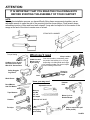
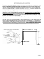
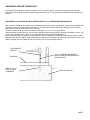
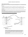
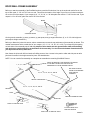
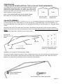
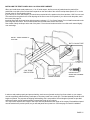
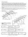
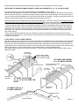
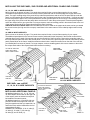
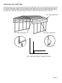
CARPORT INSTALLATION INSTRUCTIONS
FOR 4 1/2’ ON CENTER FRAMES
FRAME SIZES:
WIDTH: 10’, 12’, 14’, 18’, 20’, 24’, AND 30’
ON CENTER FRAME SPACING: 4 1/2’
FRAME LENGTH: 18’
EAVE HEIGHTS: START AT 7’ TO 12 1/2’ .
Our unique assembly process quickly transforms the individual pieces into a finished structure that will give
you a lifetime of service. Great care has been taken to ensure complete satisfaction with your purchase. In
the unlikely event that there are any missing or damaged parts, or if you simply need technical assistance,
please call our Toll Free Hotline at 1-800-900-7222 and your questions will be addressed promptly. Thank you
for choosing the Versatube Building System.
REV 10-22-09
ZINST-CM45
PAGE 1
SAFETY AND HAZARD INSTRUCTIONS
CAUTION:
Read the following safety warnings and all instructions in their entirety prior to installation. If you have
questions or are missing any parts, contact Mid-South Metal Products, Inc. (DBA, VersaTube Building
Systems) Customer Service at 1-800-900-7222 before proceeding.
WARNING:
This structure and its manufactured components are engineered per the instructions and engineering plans
provided by VersaTube Building Systems. The use of any framing components or materials in the erection
of this structure that are not produced or provided by VersaTube could negatively affect the structural integrity and will negate any warranty provisions. VersaTube Building Systems and its authorized dealers
are not responsible for any structural collapse or failure to perform resulting from additions, add-ons, or
manipulation of non-VersaTube components and/or failure to follow approved instructions.
WARNING:
Metal parts may get hot when exposed to high heat or direct sunlight. Avoid contact with skin and wear
protective gloves and clothing to prevent the possibility of burns.
WARNING:
Do not stand or walk on the structure. It is not designed to support human weight or the storage of
materials on the roof. Collapse of the structure may cause serious injury due to weight of components.
WARNING:
Avoid installation on windy days as wind may create hazards during the installation process. Wind may
blow material or cause partially installed components to collapse prior to being secured or fully installed.
The weight of the components or structure may cause serious injury if it should collapse.
WARNING:
Metal conducts electricity and electrical shock hazards exist since the structure is made of metal. During
installation or storage, keep the structure and all components away from electrical sources. Make sure that
your selected location is away from power lines, underground cables, and any other source of electrical
power. Serious injury or even death may occur if contact is made with electrical current.
WARNING:
If the structure is moved once it has been installed, be certain to inspect all components and conditions
and follow each and every step of these instructions to make certain that the structure is securely
anchored, properly installed, and aligned. Failure to follow these steps could lead to collapse of the
structure and may result in serious risk of injury.
WARNING:
In the event that your structure is enclosed, be sure to provide proper and adequate ventilation and egress
and ingress. Hazardous, poisonous or noxious substances should not be stored in the structures absent
proper ventilation and the following all warnings and instructions of the manufacturer of the substance.
Also, proper ingress and egress should be provided to prevent persons or children from becoming trapped
inside the structure.
WARNING:
If metal panels are selected to cover all or a portion of your structure, be careful of the sharp edges which
may cause cuts or lacerations. Wear protective work gloves and suitable clothing for protection and
always take care when handling metal parts.
WARNING:
Always wear safety glasses or goggles when installing self-drilling screws.
PAGE 2
ATTENTION:
IT IS IMPORTANT THAT YOU READ THE FOLLOWING NOTE
BEFORE STARTING THE ASSEMBLY OF YOUR CARPORT
NOTE:
If during the installation process you have difficulty fitting frame components together, use an
adjustable wrench to open the end of the receiving tube as shown below. Close wrench down
around bent portion of tube and bend wall outward. It may also be helpful to hit the center of the
swage at the end of the tube to create more of a lead.
STRIKE WITH HAMMER
Torque Setting
Cordless (14 or 18 volt)
Or Electric Screw Gun
With 5/16" Socket Drive
What you’ll need
Chalk Line and
Mason Line or
Nylon String
2 Step Ladders
One must be able to comfortably reach
the peak of the building 10’ to 16' high
depending on building width and height.
An extension ladder can also be helpful
when installing sheet metal.
Safety Goggles
Or glasses
Level
Shovel or
Post Hole
Digger
Work Gloves
Items you may need
Pencil/Marker
And Felt Marker
Tape Measure
Hammer
Adjustable wrench
Masonry
Drill Bit
1/2” x 8”
Drill depth
Hammer
Drill
Motor Cycle or
Ratchet Straps
Wrench, 3/4” & 1/2”
Tin Snips
Vise grip or other
quick clamp
(May be required to pull
frame plumb.)
PAGE 3
BASIC CARPORT PARTS LIST
BASE RAILS
4 1/2’ ON CENTER FRAMES:
END BASE RAIL, 2” X 3” X 83 3/4” rail with 2 welded vertical pins, swaged one end. QTY. (4), part # 71-4802
END BASE RAIL 2” x 2” x 75” rail with 2 welded vertical pins, swaged one end. QTY. (4), part # 74-4500
CENTER BASE RAIL, 2” X 3” X 56” rail with 1 welded vertical pin in center. QTY. 2, part # 71-4801
CENTER BASE RAIL, 2” X 2” X 75” rail with 1 welded vertical pin in center. QTY. (2) part # 74-4000
NOTE: The length of the carport can be extended using 4 1/2’ Base Extensions, one on each side of the carport.
2” x 3” tube, Part # 71-7050. 2” x 2” tube part # 74-7050
SIDE POST, 2” X 3” tube with a bend at one end. QTY. 10. Part # 71-5000 (7 1/2’) or # 71-5007 (7’) or # 71-5008 (8’).
SIDE POST, 2” x 2” tube with bend at one end. QTY. 10. Part #74-5000 (7’)
PEAK, 2” X 3” X 72” with one bend in the center. QTY. (5) Part # 71-6000
PEAK, 2” x 2” x 72” with one bend in the center. QTY. (5) Part # 74-6000
HEIGHT EXTENSIONS (optional) Height extensions are 2” x 3” tubes with a swage at one end. They come in net height
increments (the height from the end to the swage) of 1’ to 5’. Part # HE-1, HE-2, HE-3, HE-4, HE-5.
HEIGHT EXTENSIONS ON 2” SQUARE FRAMES ARE NOT RECOMMENDED.
RAFTERS,
10’ wide carport, 2” x 3” tube swaged both ends. Part # 71-1500, QTY. 10
12’ wide carport, 2” x 2” tube swaged both ends. Part # 74-2000, QTY. 10
12’ wide carport, 2” x 3” tube swaged both ends. Part # 71-2000, QTY. 10
14’ wide carport, 2” x 3” tube swaged both ends. Part # 71-3000, QTY. 10
18’ wide carport, 2” x 3” tube swaged both ends. Part # 71-3500, QTY. 10
20’ wide carport, 2” x 3” tube swaged both ends. Part # 71-8000, QTY. 10
24’ wide carport, 2” x 3” tube swaged both ends. Part # 71-8300, QTY. 10
30’ wide carport, 2” x 3” tube swaged both ends. Part # 71-8400, QTY. 10
2” SQUARE FRAMES COME ONLY IN A 12’ WIDTH. The rafter is Part # 74-2000
VINYL TRIM, Length will change depending on the size of the carport. Part # 9901-VTW
BUTYL TAPE, Length will change depending on the size of the carport. Part # 71-9401
FRAME SCREWS, # 12 hex head, Self-Drilling screws. Come in 70 pack #71-9999 or 40 pack # 71-9999-A
SCREWS FOR ROOF METAL, #12 X 1” painted screws with rubber washers.
VERSATUBE ANCHORS, Anchors may or may not be supplied.
REBAR ANCHOR, used with concrete. #4 x 30” rebar with welded top plate. # ANC-24 Use 1 per post.
GROUND ANCHOR, No concrete needed. 3/8” x 36” threaded rod with hex nuts, fender washers and 4” square anchor
plate. # ANC-36 Use 1 per post.
Concrete Wedge Anchors 1/2” x 7” are not supplied.
SHEET METAL PANELS, Sizes listed on page 15.
TRUSS BRACES: Truss braces may be required on your carport depending on width, wind load and snow load.
10’, 12’ and 14’ wide carports do not require a truss brace. Two types of truss braces are available. Type 2 (collar tie with
a vertical support) and type 3 (a collar tie with web angle braces and knee braces) See the part descriptions in that section.
PAGE 4
SITE PREPARATION FOR CARPORTS
The Versatube carport frame is designed to be placed on a foundation that is level side to side and sloped about 1/8” per
foot front to back or back to front. That foundation can be: prepared ground (leveled and re-compacted), a concrete
footing, or a concrete mono slab with built-in footing. It is important that you create one of these conditions prior to
your carport or building installation. We recommend that you check with your local building official prior to starting your
project to find out what is acceptable for foundations and anchoring in your county. If you extend the carport site about 3
or 4 feet on all sides, it will make it easier to position ladders for sheet metal installation.
SLAB WITH FOOTING OR FOOTINGS ALONE
If you will be pouring a slab for your carport, the slab should be 4” thick and have a footing down both sides. The footing
should be 12” x 12” with a 45° blend between the slab and the footing. The slab should have a front to back or back to
front slope of about 1/8” per foot. One run of #5 rebar mid-depth is recommended in the footing. Check with your local
building official for details and requirements in your county. Some counties require the footing to extend down 1’ below
the frost line. The concrete should be 2500 to 3000 PSI.
The outside dimensions of the slab should be at least 3” larger than your frame dimensions. Example: if you have a 20’ x
20’ frame, the slab should be at least 20’-3” x 20’-3”. This will allow the center of your anchor bolts to be 3” from the edge
of the slab.
FOOTINGS: Footings alone should be 12” wide and 12” deep and can be positioned so the base rails are centered in the
footing if you will be using wedge anchor bolts to anchor the base rails. The outside dimension of the footing will be the
carport width plus 9”. The basic carport 5’ On Center frame is 20’ long. The 4 1/2’ On Center frame is 18’ long and the 4’
On Center frame is 20’-2”. Footings should be 3” longer than your frame. Footings should also slope 1/8” per foot front to
back or back to front to allow water that might gather in horizontal ribs to flow over roof lap joints and off the roof.
Frame Width + 3”
Frame + 3”
12” Footing
PAGE 5
ASSEMBLING AND POSITIONING THE BASE RAILS:
Layout the base rails on your slab or footing or prepared ground. The base rails should be 10’, 12’, 14’, 18’, 20’, 24’, or
30’ apart (outside to outside) depending on the carport that you purchased. The length from the front to the back of the
base rail assembly will be 1/2” longer than the frame length. Example: If you have a 20’ x 18’ frame, the length of the
base rail assembly will be 18’-1/2”. The dimension from the front of the front vertical pin to the back of the back vertical
pin will be 18’.)
Join all the base rail components as shown. Check the overall length of the assembly, keep the swage joints even in
length and fasten the swage joints with (2) #12 hex head, self drilling screws per joint on top of the base rail.
Place the Left and Right base rail assemblies 10’, 12’, 14’, 18’, 20’, 24’, or 30’ apart (outside to outside) and take a
measurement across the diagonals of the frame to check it for square. Adjust the frame until the measurements are
equal.
LENGTH (OUTSIDE TO
OUTSIDE OF PINS) 18’
OPTIONAL BASE EXTENSIONS
DIAGONAL DIMENSIONS
SHOULD BE EQUAL
CARPORT WIDTH
10’, 12’, 14’, 18’, 20’, 24’ OR 30’
END BASE
CENTER BASE
END BASE
#12 HEX HEAD,
SELF-DRILLING
SCREW
LAYOUT FOR 4 1/2’ ON CENTER BASE RAILS
PAGE 6
ANCHORING CARPORT BASE RAILS:
These instructions offer three anchoring methods: (1) To a concrete slab or concrete footings with concrete wedge
anchor bolts. (2) To the ground with Versatube Ground Anchors. (3) To the ground with Versatube Rebar Anchors and
concrete.
ANCHORING TO CONCRETE SLAB OR FOOTING WITH 1/2” X 7” WEDGE (EXPANSION) BOLTS
After you have completed all measurements and have the base rails in place and squared, screw the joints together with
2 screws per joint on the top surface of the base rail. This will assure that the rails remain straight and do not vibrate
apart when you drill the anchor holes in the concrete.
To drill the anchor holes, you will need a hammer drill and a 1/2” x 8” or 12” concrete drill bit.
Hold the base rail in place with your foot, insert the drill bit through the anchor hole in the base rail and drill a hole 5” into
the concrete. The base rail is 2” thick, so the total depth from the top of the base rail will be 7”.
Place a flat washer onto the anchor bolt and screw on a hex nut until about 2 threads are exposed above the nut. Now,
place the bolt in the hole and tap it down with a hammer until the nut and washer touch the top of the base rail. Use a 3/4”
wrench to tighten the nut. Tighten the nut until it is snug. Do not crush the base rail tube.
FLAT WASHER
AND NUT
BASE RAIL
DRILL A 1/2 X 5”
DEEP HOLE IN
CONCRETE
1/2” X 7” WEDGE ANCHOR BOLT
(INSTALL ONE IN EACH BASE RAIL
ANCHOR HOLE)
SLAB OR FOOTING
PAGE 7
ANCHORING TO GROUND WITH CONCRETE PIERS
DIGGING HOLES FOR CONCRETE
Mark the locations of the rails and the anchor holes on the ground. Move the base rails to one side and dig holes at each
anchor point for concrete. You may want to rent a gas-powered post hole digger with an 8” or 12” diameter auger for this
job.
HOLE SIZE:
Counties with 70 or 80 mph Exposure C wind: Use a 12” diameter hole 14” deep or a 8” diameter hole 18” deep.
Counties with 90 mph Exposure C wind: Use a 12” diameter hole 18” deep or an 8” diameter hole 24” deep for 12’ to 20’
wide carports. For 24’ and 30’ wide carports, use a 12” diameter hole 21” deep or a 8” diameter hole 30” deep.
ANCHORING
Move the base rails back into position over the holes. Re-measure to make sure the rails are in the proper location (see
layout on page 6).
Now drop or drive a Versatube 30” re-bar ground anchor or a 1/2” x 36” threaded rod with a flat washer and nut at the
top into each anchor hole. A 24” rod could also be used. Threaded rods are normally 3’ long from your building center.
Mix up concrete and pour into holes up to ground level. You may want to rent a mixer for this job. Before the concrete
sets, re-check all your dimensions to make sure the frame is square and has the proper width.
Let the concrete cure overnight before installing the Roof/Wall assemblies.
BASE RAIL
CONCRETE
CONCRETE
1/2” THREADED ROD
WITH FLAT WASHER
AND NUT
VERSATUBE
RE-BAR GROUND ANCHOR
NOTE: If it is necessary to assemble and anchor the carport all in one work session,
you can anchor the carport after it is complete. If you assemble the frame and install
sheet metal before anchoring the base rails, it is important to have the site prepared
and level. This will allow you to get the frame square and the sheet metal properly
aligned with the frame.
PAGE 8
ROOF/WALL FRAME ASSEMBLY
Before you start the assembly of the Roof/Wall sections, stack the Peak tubes, line up the ends and mark a line on the
top of each peak 17 1/8” or 3 5/8” from one end. This will be the location of the edge of your first run of sheet metal panels on the roof of the carport. If your carport is 10’, 12’,18’, 24’, or 30’ wide place the mark at 17 1/8” from the end. If your
carport is 14’ or 20’ wide, place the mark 3 5/8” from the end.
MARK
3 5/8”
STACKED PEAKS
17 1/8”
On the ground, assemble (1) peak, (2) rafters, (2) side posts, and (2) height extensions. (8’, to 12 1/2’ side height carports require height extensions.)
Before you fasten the joints with screws, take a measurement across the top and bottom of the assembly as shown. This
outside measurement is the outside size of your carport. (10’, 12’, 14’, 18’, 20’, 24’, or 30’) Try to keep the joint spacing
on both sides of the assembly equal. It is very helpful to drive stakes into the ground at the width of the building
and use them to set the dimension at the bottom of the assembly. You should set the bottom dimension before
you adjust and set the top dimension.
Now, fasten the joints with #12 hex head, self-drilling screws. Use 4 screws in the peak to rafter and side post to rafter
joints and 2 screws in the height extension joints. See details below.
NOTE: You can use the first assembly as a template to assemble the remaining Roof/Wall Frames.
DRIVE STAKES INTO THE GROUND TO CREATE
A FIXTURE FOR SETTING THE BOTTOM
DIMENSION AT YOUR CARPORT WIDTH.
1’, 2’, 3’, 4’, OR 5’
10’, 12’, 14’, 18’, 20’, 24’, OR 30’
NO HEIGHT EXTENSIONS ON STANDARD
EAVE HEIGHT
CARPORT
HEIGHT EXTENSIONS
10’, 12’, 14’, 18’, 20’, 24’, OR 30’
RAFTER
PEAK
HEIGHT EXTENSION JOINT
SIDE POST
PEAK TO RAFTER JOINT
#12 HEX HEAD, SELFDRILLING SCREW
SIDE POST TO RAFTER JOINT
PAGE 9
TRUSS BRACING:
TYPE (2) COLLAR TIE WITH VERTICAL, TYPE (3) COLLAR TIE WITH WEB BRACES
Your carport may or may not require a truss brace depending on carport
width and the wind and snow load in your county. 10’, 12’ and 14’ wide
carports do not require truss braces. 18’, and 20’ carports often do not
require a brace. Most 24’ and 30’ wide carports require a brace. Check
with your dealer If you have questions.
TYPE 2
TYPE 3
NOTE: TRUSS BRACES ARE USED ON ALL INSIDE FRAME
SECTIONS, NOT ON THE TWO END FRAME SECTIONS.
COLLAR TIE WITH
VERTICAL BRACE
COLLAR TIE WITH
WEB BRACING
COLLAR TIE ASSEMBLY:
Collar Ties are made up of 3 parts: (1) Center Tie 2” x 2” x 111” long swaged (reduced) on both ends (part #74-1110) and
(2) end ties. End Ties are 2” square tube. On 18’ wide carports 38 1/2” (part #7400-3850), on 20’ wide carports 50 1/2”
long (part #7400-5050). On 24’ wide carports 74 1/2” long (part #7400-7450). On 30’ wide carports 111” long (part #740011100).
Assembly: Place an End Tie on both ends of the Center Tie and fasten each joint with (6) #12 hex head, self-drilling
screws. Place screws on one side of the assembly as shown. Note: Make sure the assembly is straight when you install
screws.
Install a left and right Collar Tie Bracket on both ends as shown.
COLLAR TIE
BRACKET LEFT &
RIGHT
END TIE
CENTER TIE
END TIE
SCREW PATTERN
COLLAR TIE BRACKET, (LEFT)
(RIGHT) IS A MIRROR IMAGE.
ASSEMBLY OF COLLAR TIE TO ROOF/WALL FRAME:
The collar tie must be centered in the frame. Take a measurement from the end of the side post to the collar tie bracket
on both ends of the truss brace. Adjust the brace side to side until the measurements are equal. Fasten the collar tie
brackets to the rafters with (6) self-drilling screws on each side of the assembly.
EQUAL MEASUREMENT
ON BOTH SIDES
#12 HEX HEAD, SELF-DRILLING SCREW
PAGE 10
INSTALLING VERTICAL BRACE FOR BRACE TYPE (2) TRUSS BRACE
The Center Vertical Brace is 1 1/2” square x 22 1/4” long on 18 wide carport, 25 1/4” long on 20’ wide, 31 1/4” wide on
24’ wide and 40 1/4” long on 30’ wide. Fasten the brace to the Collar Tie and the Frame Peak with Single Purlin Brackets.
Use two screws in the bracket tongue and one screw in each side flange as shown. Fasten the brackets to the vertical
brace first. Place the assembly together and adjust the parts to fit before installing any screws. Make sure that the Collar
Tie assembly is straight before you fasten the brace to the Collar Tie and Peak.
CENTER BRACE PART NUMBERS:
BRACKET PART # BK-30
18W : PART #7500-02225
20W: PART #7500-02525
24W: PART #7500-03125
30W: PART #7500-04025
#12 HEX HEAD, SELF-DRILLING SCREW
PEAK
INSTALLING WEB BRACING FOR TYPE (3) TRUSS BRACE: WEB BRACING ON 20’, 24’ AND 30’ ONLY.
STEP 1: INSTALLING THE PEAK WEB BRACKET.
Measure up from both ends of the peak to find the center and make a mark. Place a Web Bracket centered at your mark
and pressed against the bottom of the peak. Fasten the Bracket to the peak with 3 self-drilling screws as shown in detail.
BRACKET 1
PEAK
BRACKET 3
PEAK
WEB BRACE 2
WEB BRACE 1
BRACKET 2
WEB BRACE 3
BRACKET 1
WEB BRACE LENGTH
WEB BRACE 1
STEP 2: INSTALL TWO OF WEB BRACE 1: (On 20’ wide building 36” long (part # 76-3600), On 24’ wide building 46”
long (part #76-4600) and on 30’ wide building 60” long (part # 76-6000). Place one of the brace ends on top of the Web
Bracket tab and the other brace end on the bottom of the tab. Join the parts with a 3/8” x 1 1/4” hex bolt, lock washer and
hex nut. Do not tighten at this time. It may be
necessary to lift the frame to insert bolt.
PAGE 11
STEP 3: INSTALL WEB BRACE 2: (On 20’ buildings 24”) (On 24’ buildings 30”) (On 30’ wide buildings 36”) Loosely
attach Web Bracket 2 to the other end of Web Brace 1. Place the Web Bracket on the Collar Tie (make sure the collar tie
is straight and fasten the face of the bracket to the collar tie with a self-drilling screw. Remove the hex nut and attach one
end of Web Brace 2 to the Web Bracket 2 assembly. ( Like the first assembly, one brace end should be on one side of
the web bracket tab and one on the other.) Now, loosely attach Web Bracket 3 to the other end of Web Brace 2 and fasten the bracket to the under side of the rafter. Repeat assembly for remaining Web Brace 2.
WEB BRACKET 3
WEB BRACKET 1
PEAK
20W: PART #76-2400
24W: PART #76-3000
30W: PART #76-3600
WEB BRACE 2
WEB BRACE 1
WEB BRACKET 2
LOCATE BRACKET ON
COLLAR TIE.
INSERT ONE SCREW
HERE.
UNDO ASSEMBLY AND
INSTALL BRACE 3.
REINSTALL HARDWARE.
STEP 4: ASSEMBLING WEB BRACE 3: WEB BRACE 3 IS 24” LONG ON ALL CARPORTS (part #76-2400).
Measure out 1” from the end of the Collar Tie and make a mark. This will be the location of the upper Web Bracket for
Web Brace 3. Attach the upper Web Bracket with 3 self-drilling screws. Now, fasten Web Brace 3 to the upper Web
Bracket with a hex bolt, lock washer and hex nut. (Do not tighten at this time.)
Loosely attach a Web Bracket to the lower end of Web Brace 3 and place it against the side post. Re-check the building
dimension across the bottom of the frame 20’, 24’, or 30’ before attaching lower bracket to side post. Now, attach the
face to the side post with a screw, remove the hex nut, let the bolt drop down and install the two screws in the side of the
Web Bracket. Now, reinstall the bolt, lock washer and nut. Repeat assembly for remaining Web Brace 3 on the other side
of the frame.
WHEN ALL BRACES ARE IN PLACE, TIGHTEN ALL HARDWARE. The nut size is 9/16”. You may also need to hold the
bolt head with pliers.
1"
INSTALL THIS SCREW FIRST IN FACE
COLLAR TIE
SIDE POST
UPPER WEB BRACKET
WEB BRACE 3
LOWER WEB BRACKET
INSTALL THIS SCREW FIRST IN FACE
PAGE 12
INSTALLING ROOF/WALL FRAMES SECTIONS TO BASE RAILS
NOTE: This assembly will require at least two people. 24’ and 30’ frames may require more. When raising a larger frame,
the third person can walk the center of the frame up a ladder placed inside the carport.
Start at one end of the building and place a Roof/Wall frame assembly (one with no truss brace) on the first base rail
vertical pins. Fasten joints with two screws each. Keep the screw heads away from the outside of the building where
sheet metal may be installed. Check the bottom ends of the side posts or height extensions for dimples that might
interfere with assembly to base rail pins. Dimples must be removed. (See page 2.)
Repeat this assembly until all Roof/Wall frame assemblies are installed. ( Remember, no Truss Braces at the ends of the
Carport.)
Place bottom of side posts on
base rail pins at an angle.
Raise frame section and drop
It onto pins at the same time
on both sides of the carport.
Tap lightly on the side post
with a hammer if parts do not
drop into place.
BASE RAIL PIN
SQUARING UP YOUR FRAME
Before you install sheet metal, you may want to check the
Roof/Wall assemblies to make sure they are plumb and
square and that the side post heights are equal.
To do this, first check the front and back Roof/Wall sections to make sure that they are plum side to side. Check
the outside of the side post. If adjustments must be made,
you can drive a wooden or metal stake into the ground
about 8’ from the building and use a Motor Cycle strap or
Ratchet strap to pull the side post into plumb. Place a
clamp on the side post as shown and attach the strap
above the clamp.
#12 SELF-DRILLING SCREW
HAMMER
STRING
CLAMP
MOTOR CYCLE
When the front and back sections are plumb (side to side), STRAP
tie two strings from the front side post to the back side post
at the bottom and top of the bend radius as shown. These
strings will let you see which sections are high, low or out
of plumb. If the side posts are high or low, remove the joint
screws and raise the low posts and hammer down the
SIDE POST
higher posts as much as possible. Reinstall the screws in a
new location. Check the height of the side posts on both
sides of the building. The straps should remain in place
until several runs of roof metal have been installed.
Note: This is not a critical step, but it may improve the
appearance of your building. If side posts are out of plane
with the other side posts more than 1/4”, it may be visible.
PAGE 13
INSTALLING HORIZONTAL SHEET METAL ON THE CARPORT FRAME:
Different lengths, styles, and gauges of sheet metal panels can be installed on the Versatube frame. With the use of
optional roof purlins, you can also install vertical sheet metal panels. For the purpose of these assembly instructions, we
will be using sheet metal panels run horizontally. These instructions will cover the installation of roof and partial side
panel coverage only.
Note: Adding additional side panels will effect the wind load applied to your structure. If you intend to add additional
panels, you may require additional bracing or closer On Center spacing of the frame sections.
Carport Panel lengths for:
4 1/2’ On Center frame sections: 10’, 9’-2”, 4’-8”.
The panel length listed first above (10’) will always go at the ends of the roof and create an overhang of 11” on both ends
of the frame. The other lengths are designed to span ether 2 or 3 interior frame sections.
STEP 1: Installing Panel 1 (10’ for 4 1/2’ on center frame sections.)
On the bottom of the panel, put a light pencil mark to indicate the overhang. (11”) This line will help you keep the overhang square with the end of the frame.
THE FIRST PANEL SHOULD BE INSTALLED ON THE LOW END OF THE CARPORT FOR PROPER DRAINAGE.
Before you assembled the Roof/Wall sections, you should have put a mark on one side of each peak as a guide for the
under lap edge of the first run of panels down the peak of the carport. If you did not, refer to page 10 for the proper mark
location for your building width.
Note: The illustration below is for 10’, 12’, 18’, 24’ and 30’ wide carports. See next page for 14’ and 20’ carports.
Place the first panel on the roof with the under lap edge of the panel lined up with the marks on the peaks and the end of
the panel overhanging the end of the building 11” (see notes above). You may want to clamp the panel in place while
installing the screws. With the panel lined up with all your marks, attach the panel to the first frame section with painted
#12 x 1” self-drilling screws with rubber washers about 1” above the major ribs. Do not install screws above the edge
ribs at this time. You will be sliding the lower panels under the edges of the panels above.
Before you install screws in the second frame section, check to see that it is square with the first section. Take a measurement between the frame sections at the base rail and transfer that dimension up to the peaks. Now, install screws in
the second frame section. The other end of the panel should line up with the back of the third frame section. Do not install
screws into the third frame section at this time.
Run a strip of Butyl Caulk Tape across the end of the panel 1” from the end as shown below. Let a little bit hang over
the edges.
NO SCREWS ABOVE
EDGE RIBS OR INTO
THIRD FRAME SECTION
BUTYL CAULK TAPE
11” OVERHANG
1”
17 1/8” FROM
END OF PEAK
PAINTED #12 X 1”
SCREW WITH RUBBER
WASHER
UNDER LAP EDGE
VIEW FROM THE LOW END OF THE CARPORT
PAGE 14
INSTALLING THE FIRST PANELS ON A 14’ OR 20’ WIDE CARPORT
When you install sheet metal panels on a 14’ or 20’ wide carport, the first course of panels down the peak will be
positioned to one side of the roof and the first panels on the other side of the roof will overlap these panels 10” or to the
second major rib. See illustration below.
If you have a 14’ or 20’ wide carport, you should have marked all of the peaks on the frame sections 3 5/8” from one end.
This mark will be the guide for the under lap edge of the first course of roof panels. If you did not mark the peaks, mark
them now. See page 10.
Install the first panel as shown below with the proper overhang (11” ) On Center frames). Do not install screws above the
lower edge ribs at this time . Do not install screws into the third frame section at this time.
Run a bead of butyl caulk tape at the end of the panel 1” from the end as shown below. Let a little caulk extend slightly
over each edge.
INSTALL THESE SCREWS AT
THIS TIME
BUTYL CAULK TAPE
1”
3 5/8” FROM
END OF PEAK
UNDER LAP EDGE
PAINTED #12 X 1”
SCREW WITH RUBBER
WASHER
11” OVERHANG
In order to seal panels properly and prevent leaking, each course of panels running from front to back on your carport
must be completely sealed with butyl caulk tape or clear butyl caulk from a caulk gun. The ideal assembly would have full
length roof panels. For purposes of shipping and handling, this is not possible. Several lengths of panels are provided
and these lengths must be sealed together to extend the length of your carport.
You may have a carport that is longer or has more than two panels down the length of the carport. Each additional panel
must be sealed to the previous panel, as you will seal panel two to panel one. See next page for Panel 2 installation.
PAGE 15
INSTALLING PANEL TWO
If you have not removed the protective paper on the butyl tape that you applied to panel 1, do that at this time.
Now, position panel two as shown below with a 2” overlap on panel one. Press the panels together well to create a good
seal with the butyl caulk. The lower (under lap) edge of the panel should line up with the marks on the peaks. Before you
install screws, make sure that the third frame section is the same distance from the second frame section at the base rail
and at the peak. Attach the panel with screws on both sides of the major ribs at the lap joint and above the major ribs at
other locations. Do not install screws above the lower edge rib or at the end of panels that continue on down the roof.
NOTE: The second panel will also be 10’ long if your frame is only 18’ long. This panel will overhang the other end of the
carport frame.
REMEMBER: On longer carports (with extensions), the end panels are the same length, center panels are shorter.
ADDITIONAL PANELS DOWN CARPORT LENGTH: Install additional panels down the length of the carport as needed in
the same manner as you installed panel 2. See diagram below for panel guide.
SCREWS ON BOTH
SIDES OF RIB AT JOINT
NO SCREWS ABOVE
LOWER EDGE
11”
OVERHANG
12’, 18’, 24’ AND 30’ WIDE FRAMES
PANEL LENGTHS FOR 4 1/2’ ON CENTER
FRAMES.
NOTE: On longer carports, you will have additional long center panels.
END PANEL 10’
SHORT PANEL ,
4’-8”
14’ AND 20’ WIDE FRAMES
END PANEL 10’
CARPORT WITH 1 LENGTH EXTENSION
END PANEL 10’
LONG CENTER PANEL 9’-2”
END PANEL 10’
CARPORT WITH 2 LENGTH EXTENSIONS
END PANEL 10’
SHORT PANEL
4’-8”
LONG CENTER PANEL 9’-2”
CARPORT WITH 3 LENGTH EXTENSIONS
END PANEL 10’
PAGE 16
Install all panels down the peak of the carport before moving on to the second lower course of panels.
INSTALLING THE SECOND LOWER COURSE OF PANELS ON CARPORTS 10’, 12’, 18’, 24’ AND 30’ WIDE
The second course of panels will be installed starting at the opposite end of the carport.
Slide the under lap edge of the first panel of the second course under the lower edge of the last panel in the first course.
Note: On one side of the roof, you will be inserting a under lap edge under an under lap edge. This is fine and it only occurs once. In the rest of the installation, the under lap rib will go under an overlap rib. Install the screws at the end of the
carport to hold the panel in place. (No screws above the lower edge at this time.)
Select the next panel to be installed and run a bead of butyl caulk tape on one end 1” from the end. The panel should be
positioned with the under lap edge on the upper side of the panel. Remove the protective paper from the butyl caulk.
Now, lift the end of the panel you just installed and the edge of the first course of panels above and insert the next panel
2” under the previous panel. Check your dimensions and press the panel overlap tightly together. Install screws in the
overlap joint and all screws in the previous panel and the panels above that will not have to be lifted to insert additional
panels. Note: To reach all of the screw locations, you will have to get up high on your ladder and lean on the roof with
your hand or knee. When you do this, press only on the flat sections between ribs and make sure that you press only
over a frame section.
Continue this installation method until the roof is sheeted on one side. The last panel on the side will be bent down
around the frame and become a short side panel. Start all panels courses from the end of the carport that you started the
second course of panels.
IF YOU HAVE A 14’ OR 20’ WIDE CARPORT
Start the second course of panels at the end of the carport where you started the first course of panels. Lap the underlap
edge of the first panel in the second course over the peak of the roof and onto the second major rib of the last panel in
the first course. (See lap detail below.) Install several screws above the edge rib from the side of the carport that you installed the first course of roof metal (no screws into the end of the panel at the third frame section). Now, press the panel
down at the peak and on the other side of the roof and install screws in locations indicated below.
Run a bead of butyl caulk tape on the end of the panel 1” in from the end. Extend the ends of the tape a little over the
edges of the panel.
1ST PANEL
2ND COURSE
SLIDE PANEL UNDER
FIRST COURSE AND INSTALL SCREWS AT END
1ST PANEL, 2ND COURSE
14’, & 20’ WIDE CARPORTS
OVERLAP EDGE
BUTYL CAULK THIS END
NO SCREWS YET
1ST PANEL
2ND COURSE
LOW END OF
CARPORT
1ST PANEL, 2ND COURSE
10’, 12’, 18’, 24’ & 30’ WIDE CARPORTS
LAP DETAIL FOR 14’ &
20’ WIDE CARPORTS
LOW END OF
CARPORT
UNDERLAP EDGE
OVERLAP EDGE
PAGE 17
INSTALLING THE 2ND PANEL, 2ND COURSE AND ADDITIONAL PANELS 2ND COURSE
12’, 18’, 24’, AND 30’ WIDE CARPORTS:
See the chart on the bottom of page 17 for panel sizes required for the on center frame spacing of your carport.
The additional panel/panels in the second course must be positioned with the underlap edge to the upper side of the
panel. The upper underlap edge of the panel will lap under the panel above and the end of the panel will lap under the
panel you just installed. Run a bead of butyl caulk on the end to be lapped under the previous panel 1” from the end and
remove the protective paper. Now, lift the panels above and the previous panel in the course you are installing and slide
the upper edge of the panel under the panel above and the end 2” under the previous panel. Press the panels together
well at the caulked end to get a good seal. For longer carports, continue installing panels in the same manner to the end
of the carport. Both ends of the carport should have the same overhang.
Additional Courses of Sheet metal: Start all additional courses of metal on the carport at the same end as you started
the second course (the high end of the carport). Install them in the same manner. Place underlap edges under overlap
edges.
14’ AND 20’ WIDE CARPORTS:
See the chart on the bottom of page 17 for panel sizes required for the on center frame spacing of your carport.
The additional panel/panels in the second course must be positioned like the first panel in the second course with the
underlap edge over the peak of the carport and onto the second rib of the first course. Remove the protective paper on
the butyl caulk and place the end of the second panel 2” over the end of the previous panel. With the ribs lined up and the
panel pressed down to the frame, install the screws as shown below. Install the screws first on the side of the roof that
you installed the first course of panels. For longer carports, continue installing panels in the same manner to the end of
the carport. Both ends of the carport should have the same overhang.
2ND PANEL
2ND COURSE
LIFT END OF PREVIOUS
PANEL AND PANELS
ABOVE. INSERT PANEL
LOW END OF
CARPORT
2ND PANEL
2ND COURSE
BUTYL CAULK
2ND PANEL, 2ND COURSE
12’, 18’, 24’ & 30’ WIDE CARPORTS
INSTALLING ADDITIONAL PANELS:
All additional panels on 10’, 12’, 18’, 24’ and
30’ wide carports should start on the high end
of the carport (same as second course) and
be installed in the same manner.
All additional panels on 14’ and 20’ wide carports should start at the high side of the carport (the opposite end that you started the 1st
and 2nd course) and be installed like the 3rd
course shown at right.
NUMBER OF COURSES: 10’ & 12’ wide (5),
14’ wide (6), 18’ wide (7), 20’ wide (8),
24’ wide (9), and 30’ wide (11).
1”
LOW END OF
CARPORT
2ND PANEL, 2ND COURSE
14’ & 20’ WIDE CARPORTS
LIFT END OF PREVIOUS
PANEL AND PANELS
ABOVE. INSERT PANEL
WITH CAULK
1ST PANEL
3RD COURSE
BUTYL CAULK
LOW END OF
CARPORT
2ND PANEL
3RD COURSE
1”
PAGE 18
INSTALLING VINYL EDGE TRIM:
Install vinyl edge trim on front, back and side edges of sheet metal panels. Start at one corner and push the trim securely
over the sheet metal edge. Install the trim on the gable ends first starting at one corner, up along the gable and down to
the other corner. Install vinyl edge trim on both side edges of the carport. Clip the trim flush with the edge of the trim on
the gable ends. It may help to use a small hammer to fit trim over major ribs. Use your tin snips to cut the trim.
VINYL TRIM, GABLE END
VINYL TRIM, GABLE END
VINYL TRIM, SIDE EDGE
BUTT SIDE EDGE TRIM UP TO GABLE END TRIM
PAGE 19