1
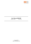
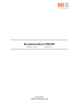
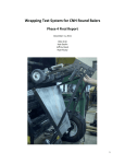
DSE4200 Installation guide Document No.: D3702-019 Version: 02.01.00 13 August 2015 DSE Test Solutions A/S DSE4200 Installation guide Contents 1. GENERAL DATA ................................................................................................................ 3 1.1 2. Scope ............................................................................................................................................. 3 INSTALLATION GUIDANCE STEP BY STEP .................................................................... 3 2.1 List of parts for DSE4200 .............................................................................................................. 3 2.2 Installation...................................................................................................................................... 3 2.2.1 Step 1. ................................................................................................................................... 4 2.2.2 Step 2. ................................................................................................................................... 7 2.2.3 Step 3. ................................................................................................................................... 8 2.2.4 Step 4. ................................................................................................................................... 8 2.2.5 Step 5. ................................................................................................................................... 9 2.2.6 Step 6. ................................................................................................................................. 10 2.2.7 Step 7. ................................................................................................................................. 10 3. TROUBLESHOOTING ...................................................................................................... 10 4. WIRING OF DSE4200 IN BALER AND TRACTOR .......................................................... 11 5. SCHEMATICS OF DSE4200 CABLE SET ....................................................................... 12 Version history Version 01.00.00 01.01.00 02.00.00 Date 140610 140714 2015.03.06 Prep. LP LP TT Status Closed Closed Closed App. PEN PEN PDL/ LP 02.01.00 2015.08.12 PEN Closed TT Change Description First Release Troubleshooting Section added (Section 3) Added chapter 4, overview. Added USB and cable numbers in 2.1. Added reference to chapter 4 and changed orders of steps in 2.2. Added header 2.2.1.1 Added info about Power source in 2.2.5. Added info about 7 pin trailer connector in 2.2.6.. Reset changed to Zero Adjust in 2.2.7. Review by PEN: Small changes, Troubleshooting moved to User Manual. Released after review and minor adjustments. Added schematic of cable set to section 5 DSE Test Solutions A/S, 13 August 2015 Project no.: 3702 Document no.: D3702-019 2 2 of 12 Version no.: 02.01.00 DSE4200 Installation guide 1. General data The English version of this document is the original installation guide and a base for translations to other languages. 1.1 Scope This document should make it possible for the daily user to install the DSE4200 moisture measuring equipment. 2. Installation guidance step by step 2.1 List of parts for DSE4200 Congratulations with your new microwave based DSE4200 Moisture Meter system. DSE4200 Moisture Meter system consists of the following parts: 1 RX unit. 1 TX unit. 1 Display. 2 Mounting brackets for the RX and TX units. 1 Mounting bracket for the proximity switch. Cable for mounting between RX and TX units and proximity switch. (-W3, -W4, -W5) Cable from Display to TX and Power source. (-W1, -W2) DSE4200 USB memory stick 2.2 Installation For overview of the installation, refer to Chapter 4 “Wiring of DSE4200 in Baler and Tractor.” The installations process is relatively simple and the best result is achieved by following these steps. DSE Test Solutions A/S, 13 August 2015 Project no.: 3702 Document no.: D3702-019 3 3 of 12 Version no.: 02.01.00 DSE4200 Installation guide 2.2.1 Step 1. Secure the Moisture Meters immediately after the channel using the brackets included. Screw or weld them onto the frame on both sides. To the extent possible, place the Moisture Meters in the bale's height direction, allowing the black part to point towards the bale. It is important that the Moisture Meters are mounted parallel, opposite each other. The angle and parallelism is not critical within a couple of degrees or mm. as long as “Zero adjust” and measurements are made with the TX/RX units in the same position. It is very important that the TX and RX units are mounted horizontally. If the Moisture Meters are positioned vertically, they will not measure correctly. See picture below. It is not necessary that the Moisture Meters are in contact with the bale. A distance of 3-5 cm of air between the Moisture Meter and bale is fine. The bale width is configured in the Display software during first time use. 2.2.1.1 Alternative mounting of TX and RX units As an alternative, the Moisture Meters can be mounted in the bale channel just before the exit, by cutting a hole in the side walls between the ribs, equal the size of the protection plate (175mm x 80mm). Not all baler models have sufficient space between the ribs to fit with the moisture meter. There need to be minimum 80 mm free space between the ribs, if not the mounting in the bale channel is not possible. Please check this first. To avoid damage to the Moisture Meter, there need to be mounted a protection plate in front of the Moisture Meter, as shown on the drawing below. The protection plate is considered a wearing part and needs to be replaced from time to time when worn out. This protection plate, need to be in a material transparent for microwaves. This is delivered on request from DSE Test Solutions as accessories. DSE Test Solutions A/S, 13 August 2015 Project no.: 3702 Document no.: D3702-019 4 4 of 12 Version no.: 02.01.00 DSE4200 Installation guide The protection plates needs to be mounted with the front in line with the inside of the baler channel wall. When mounting the Moisture Meter, it must be fastened to support the protection plate. Please make sure the pressure from the Moisture Meter on the protection plate is not so hard that the protection plate starts bending. Adjustments in the distance between the moisture meter and the brackets might be required to ensure the right distance, depending on the height of the baler side ribs. This can be done by adding washers or spacers. DSE Test Solutions doesn’t deliver the mounting brackets for mounting in the baler channel, as those needs to be individual for different baler models. Example of mounting in the baler channel: Example 1: DSE Test Solutions A/S, 13 August 2015 Project no.: 3702 Document no.: D3702-019 5 5 of 12 Version no.: 02.01.00 DSE4200 Installation guide Example 2: The picture below shows the inside of the channel. The metal strip welded to the wall before the TX/RX unit minimizes buildup of material around the TX/RX units that might damage them. DSE Test Solutions A/S, 13 August 2015 Project no.: 3702 Document no.: D3702-019 6 6 of 12 Version no.: 02.01.00 DSE4200 Installation guide 2.2.2 Step 2. The proximity switch is mounted at the tips of the star wheel as illustrated on the pictures. Fasten with bracket included. Attach the cable as illustrated and connect to the Moisture Meter. Adjust the distance between the proximity switch and the teeth of the star wheel to approx. 4-5 mm. Check that the star wheel rotates freely by turning it manually. When power is switched on to the Moisture Meter, there is a led on the proximity switch which lights up when a tooth of the start wheel is passing. Please check this is turning on and off when the star wheel is turned. If not, then the distance between the proximity switch and the star wheel needs to be adjusted. This is important as the star wheel is the trigger to the system. The system performs one measurement every time a tooth is passing the proximity switch. DSE Test Solutions A/S, 13 August 2015 Project no.: 3702 Document no.: D3702-019 7 7 of 12 Version no.: 02.01.00 DSE4200 Installation guide 2.2.3 Step 3. Insert the plugs in the Moisture Meters and connect by pulling and securing the cable underneath the channel. 2.2.4 Step 4. Draw the cable from the moisture meter to the front end of the baler. Make sure the cables are drawn in a way that protects the cables in the best possible way, and keep the cables safe from moving parts on the baler. The way to do this will be individual depending on the baler model. DSE Test Solutions A/S, 13 August 2015 Project no.: 3702 Document no.: D3702-019 8 8 of 12 Version no.: 02.01.00 DSE4200 Installation guide 2.2.5 Step 5. The display is mounted in the cockpit of the tractor and the cable (-W2) is pulled to the rear end of the tractor. Connect “–W1” to DC power source (The blue supply wire to minus (Ground) and the red to plus 12 volt). The fuse holder on the cable contains a 3.15A fuse. If this is not used, then a similar fuse needs to be mounted where the power is connected to the moisture meter. NB: To ensure that the DSE4200 does not drain the battery when the tractor is not running, connection must be made to a switched power source. On the picture you see an example of a display mounting position. Avoid placing the Display in areas where it can be exposed to direct sunlight. DSE Test Solutions A/S, 13 August 2015 Project no.: 3702 Document no.: D3702-019 9 9 of 12 Version no.: 02.01.00 DSE4200 Installation guide 2.2.6 Step 6. Connect the plugs as illustrated. NB: These 7 pin trailer connectors are for DSE4200 use only and must not be connected to other equipment than DSE4200 or damage may occur. 2.2.7 Step 7. Turn on the display and follow the installation procedure for parameter set up and Zero Adjust. 3. Troubleshooting Refer to User Manual Troubleshooting DSE Test Solutions A/S, 13 August 2015 Project no.: 3702 Document no.: D3702-019 10 10 of 12 Version no.: 02.01.00 DSE4200 Installation guide 4. Wiring of DSE4200 in baler and tractor DSE Test Solutions A/S, 13 August 2015 Project no.: 3702 Document no.: D3702-019 11 11 of 12 Version no.: 02.01.00 DSE4200 Installation guide 5. Schematics of DSE4200 cable set DSE Test Solutions A/S, 13 August 2015 Project no.: 3702 Document no.: D3702-019 12 12 of 12 Version no.: 02.01.00